Gas barrier properties of polymer/clay nanocomposites

Yanbin Cuia, S. Kumar*ab, Balakantha Rao Konac and Daniel van Houckec
aInstitute Center for Microsystems (iMicro), Department of Mechanical and Materials Engineering (MME), Masdar Institute of Science and Technology, P.O. Box 54224, Abu Dhabi, U.A.E.. E-mail: kshanmugam@masdar.ac.ae; skumaar@mit.edu; s.kumar@eng.oxon.org
bDepartment of Mechanical Engineering, Massachusetts Institute of Technology, Cambridge, MA 02139-4307, USA
cInnovation Centre, Borouge Pet. Ltd., P.O. Box 6951, Abu Dhabi, U.A.E.

Received 1st June 2015 , Accepted 17th July 2015

First published on 20th July 2015


Abstract

In the field of nanotechnology, polymer nanocomposites (PNCs) have attracted both academic and industrial interest due to their exceptional electrical, mechanical and permeability properties. In this review, we summarize the state-of-the-art progress on the use of platelet-shaped fillers for the gas barrier properties of PNCs. Layered silicate nanoclays (such as montmorillonite and kaolinite) appear to be the most promising nanoscale fillers. These exfoliated nanofillers are able to form individual platelets when dispersed in a polymer matrix. The nanoplatelets do not allow diffusion of small gases through them and are able to produce a tortuous path which works as a barrier structure for gases. The utilization of clays in the fabrication of PNCs with different polymer matrices is explored. Most synthesis methods of clay-based PNCs are covered, including, solution blending, melt intercalation, in situ polymerization and latex compounding. The structure, preparation and gas barrier properties of PNCs are discussed in general along with detailed examples drawn from the scientific literature. Furthermore, details of mathematical modeling approaches/methods of gas barrier properties of PNCs are also presented and discussed.

1. Introduction

The field of nanoscience has blossomed over the last two decades, and the importance for nanotechnology will continue to increase as miniaturization becomes more important in many applications.1 As one of the most important branches of current nanotechnology, fabrication of polymer nanocomposites (PNCs) is critical to realizing new generation materials with high performance and multi-functionality.2 PNCs are produced by dispersing inert fillers that have one or more dimensions on the nanometer scale (<100 nm) into a polymeric matrix.3,4 Compared to their conventional polymer composites and pure polymers, PNCs exhibit enormously enhanced properties and higher performance due to high aspect ratio and surface area of nanofillers. Addition of nanofillers does not increase the density of the polymer. Moreover, the polymer's optical properties and recyclability of PNCs remain unaffected.5 The research on polymer/clay nanocomposites can be traced back to Toyota's work in the latter part of the 1980s, in which PNCs were prepared by dispersing the exfoliated clay in nylon-6.6 Significant improvement in the mechanical properties and the discovery of new properties of the composites have also been realized by reinforcing polymer with clay at nanoscale.7–9 Since then, many researchers have been exploring this emerging area of research and a huge number of papers have been published.9,10 Recent interest in polymer matrix based nanocomposites has emerged initially with interesting observations involving exfoliated clay, carbon nanotubes, carbon nanofibers, exfoliated graphite (graphene), nanocrystalline metals and a host of additional nanoscale inorganic fillers or fiber modifications.11 PNCs represent exciting and promising composites owing to their markedly improved performance in mechanical, thermal, electrical, optical, permeability and corrosion protection properties of polymers.4,5,11–37

Due to their functionality, lightweight, ease of processing, and low cost, polymers have replaced conventional materials (e.g., metals, ceramics and paper) in packaging applications over the last twenty years. For instance, the food packaging industry is constantly searching for ways to reduce the gas permeability rate of packaging materials so as to extend the shelf life of products. The use of synthetic polymers is ubiquitous in food packaging where they provide mechanical, chemical, and microbial protection from the environment and allow product display. According to global polymer market survey, more than 40% of polymers have been used as packaging materials and almost half of them are used for food packaging in the form of films, sheets, and bottles, etc.20,27,38 Polymers most frequently used in food packaging are polyethylene (PE), polypropylene (PP), polystyrene (PS), polyvinyl chloride (PVC), and polyethylene terephthalate (PET), etc.16,39 However, despite their enormous versatility, a limiting property of polymeric materials in food packaging is their inherent permeability to gases and vapors, including oxygen, carbon dioxide, and organic vapors.16 The penetration of gas into polymer films has a critical effect on their service performance. Permeability is a critical performance issue in many areas such as, packaging, construction, water, gas transportation, electronics, aerospace, etc. Barrier polymers have become more and more important in many packaging and protective applications, such as food industry, pharmaceuticals and electronic devices (e.g., flexible displays).16,35,40 The frequently used strategies to improve barrier properties are the use of PNCs, polymer blends, coating with high barrier materials and multilayer films containing a high barrier film.16 Compared to PNCs, polymer blends and multilayer films have higher production and materials costs, require the use of additional additives and adhesives that complicate their regulation by federal agencies, and entail added difficulty when it comes to recycling.3 Nevertheless, there is still a significant push in the polymer industry to generate PNC films with improved gas barrier properties. Therefore, considerable research effort has been devoted to develop new strategies for enhancing barrier properties and to understand the structure–barrier properties relationship of PNCs.2,14,27,34,35,37,41–43

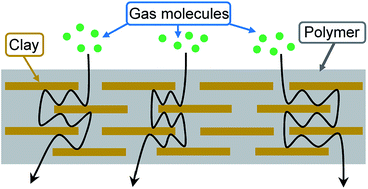
The barrier properties of polymers can be significantly enhanced by inclusion of impermeable lamellar fillers, such as montmorillonite (MMT) and graphene, with sufficient aspect ratio to alter the diffusion path of gas-penetrant molecules.44 The key challenge is to obtain an effective dispersion and exfoliation of the nanofillers in the polymer matrix to yield well aligned high aspect ratio particles for mechanical reinforcement and/or a tortuous diffusion pathway for improved barrier properties of PNCs.10 These nanofillers can block gas molecules diffusion and increase the tortuosity. This results in an extended and tortuous travelling pathway of the diffusing gas through the PNCs to improve the gas-barrier properties of the composites (Fig. 1).35 Moreover, addition of nanoplatelets results in modification of polymer chain mobility via interfacial adhesion between nanoplatelets and polymer matrix, which consequently provides lower available free volume for diffusing gas molecules and changes the solubility parameters.45 Mathematical models and empirical studies suggest that the keys to obtain PNCs with excellent permeability are to maximize the aspect ratio of the nanoplatelets, to orient the surface of each nanoplatelets perpendicular to the direction of the gas diffusion path and to enhance the interfacial adhesion between nanoplatelets and the polymer matrix.25,38,42,46–48 Nevertheless, it is an extremely challenging task to achieve good dispersion as well as regular arrangement of the nanoplatelets within polymer matrix. Therefore, PNCs with high barrier performance has been desired for a long time and spurred intense research activity over the last twenty years.2,9,14,16,42,49–52


image file: c5ra10333a-f1.tif
Fig. 1 “Torturous diffusion path” in polymer/clay nanocomposite.14

Owing to their unique layered structure, rich intercalation chemistry and availability at low cost, clay minerals are promising nanoparticle reinforcements for polymers to manufacture low-cost, lightweight and high performance nanocomposites.5 Polymer/clay nanocomposites exhibit excellent properties (high mechanical, gas barrier and thermal properties) even with the addition of a small amount of clay.9 In particular, talc and mica had been traditionally attracting the most interest.52 Currently, Na+-montmorillonite (Na+-MMT) clay is widely used in the preparation of PNCs because its lamellar elements exhibit high in plane strength, stiffness, and high aspect ratio.53 Although, a comprehensive review on the enhanced and novel properties of polymer/clay nanocomposites (including mechanical, thermal, barrier and electrical conductivity) have been reported by Zeng et al. in 2005,5 there is a lack of extensive review on the gas barrier properties of PNCs. Moreover, the wide-range of ongoing research activities in the area of barrier performance of polymer/clay nanocomposites encourages further review in order to capture the trends, accomplishments and challenges. On account of emerging trend in using nanoplatelets to improve the properties of PNCs, this review highlights the influence of clay on the barrier properties of PNCs. First, current progress on the fabrication of polymer/clay nanocomposites is reviewed. Then, the gas permeability of PNCs in relation to their structure and processing methods (melt and solution intercalation, in situ polymerization, etc.) are discussed. Lastly, the mathematical modeling aspects of gas barrier properties of PNCs are delineated.

2. Clay-based polymer nanocomposites

2.1 Exfoliation of layered clay into individual platelets

The fabrication of PNCs, which are intended to provide a synergetic effect by taking advantage of the high workability of polymers and nanofillers, is a useful method to significantly improve the physical properties of polymers.35 Although several nanoplatelets have been recognized as possible additives to enhance the performance of PNCs, the industry has focused its attention mainly on layered inorganic fillers like clays and silicates, due to their richest intercalation chemistry, high strength and stiffness, high aspect ratio of individual platelets, abundance in nature and low cost.5,40 The incorporation of clay platelets into polymers initially attracted attention because of improvements in mechanical properties of polymer.54,55 Subsequent investigations addressed other properties, such as improved barrier properties and resistance to solvents and flames.33,37,56–69

The most widely used clay filler for the enhancement of gas barrier property of PNCs is MMT as it has large cation exchange capacity.40,70 MMT is a hydrated alumina-silicate layered clay (a 2[thin space (1/6-em)]:[thin space (1/6-em)]1 type) and its structure consists of an edge-shared octahedral sheet (in such a way that the oxygens from the octahedral sheet also belong to the silica tetrahedra) of aluminium oxide (AlO6), sandwiching between two layers of tetrahedral silicon oxide (SiO4) to form a platelet structure (see Fig. 2).40,52,71 Each platelet has an average thickness of ∼1 nm and a length or breadth from a few tens of nm up to 1 mm, which represents filler with a significantly large aspect ratio.3,72 MMT is a naturally occurring form of clay in which certain aluminium ions located between the plate-shaped layers exchange with other cations (typically Fe, Mg, or Li) to create a negative charge at the platelet surface.9,72 The negative charges are counterbalanced by some cations, such as Na+ in the gallery.73 Because of the presence of cations adsorbed on the silicate layer, the cations inside the gallery can be easily exchanged with organic ions, such as ammonium, phosphonium and sulfonium, giving the MMT cation-exchange capabilities.9,74 MMT treated with an organic modifier is called organo-modified MMT (O-MMT) and it becomes compatible with organic materials.9


image file: c5ra10333a-f2.tif
Fig. 2 Structure of MMT (phyllosilicate clay).3

It is well known that the morphology and dispersion of clay nanoplatelets in polymers is one of the key factors affecting their gas barrier properties.10,75 Therefore, the ability to incorporate clay nanoplatelets into a polymeric matrix with a high level of exfoliation and orientation is one of the most important challenges in the fabrication of polymer/clay nanocomposites with improved barrier performances.76 There are three possible morphologies within polymer/clay nanocomposite systems: phase-separated, intercalated, and exfoliated (see Fig. 3).16,40,77 Within phase-separated nanocomposites, clay tactoids are formed throughout the matrix and no separation of clay nanoplatelets occurs. Polymer chains surround clay nanoplatelets but do not penetrate between the clay layers.78 The lack of platelet separation may result in large, micron-sized agglomerates. In intercalated nanocomposites, some of the polymer molecular has penetrated the interlayer galleries of the clay tactoids. Due to the penetration of polymer chains, the spacing between individual clay platelets will increase, but the overall order of the clay layers is maintained.79 In exfoliated nanocomposites, the clay layers are completely separated and dispersed individually within the continuous polymer matrix. Exfoliated nanocomposites produce the highest surface area interaction between clay nanoplatelets and fine polymer.11 Once exfoliation has been achieved, the improvement in properties can be manifested in barrier properties, as well as enhanced mechanical properties, decreased solvent uptake, increased thermal stability and flame retardance.80 However, homogeneous dispersion of most clays in organic polymers is not easy due to the preferential parallel stacking of the clay nanoplatelets and hydrophilicity of its surface.79 The drawback of clays is the incompatibility between hydrophilic clay and hydrophobic polymer, which often causes agglomeration of clay mineral in the polymer matrix.16,80 Therefore, surface modification of clay minerals for a good compatibility with the polymer is the most important step to achieve homogeneous dispersion of clay nanoplatelets in polymer matrix.5,10 The Na+ and Ca2+ residing in the interlayer regions of clay nanoplatelets usually can be replaced by organic cations by a cationic-exchange reaction to render the hydrophilic-layered silicate organophilic.53,81 A proper organophilization is a key step for successful exfoliation of clay particles in polymeric matrices. The organophilization reduces the energy of the clay and improves its compatibility with organic polymers.40,67


image file: c5ra10333a-f3.tif
Fig. 3 The possible morphologies of polymer/clay nanocomposites.16

The layer structure of clay could be totally exfoliated into individual nanoplatelets using different methods, such as the phase inversion of amphiphilic copolymer emulsifiers and phase transitions that involve zigzag Mannich polyamines.61 For example, the intercalation of the layered structure of Na+-MMT by amphiphilic comb-like copolymers produce a low interlayer spacing of 19.5 Å.82 However, the layered structure could be further exfoliated into randomization in a closed system at 120 °C and 36 atm of N2 (Fig. 4).83 The hydrophilic polyoxyethylene (POE)–amine pendants and the hydrophobic PP backbone of the comb-like polymers afforded amphiphilic control of the exfoliation. The transformation process from the initially layered silicates into randomized individual silicate platelets was thermodynamically controlled and attributed to the phase inversion from a water-in-oil (W/O) to an oil-in-water (O/W) type of randomization.61 Chu et al. synthesized exfoliating agent from the Mannich reaction of polyoxypropylene (POP)–diamine (2000 Mw) with p-cresol and formaldehyde (Fig. 5).84 By treating with different equivalents of hydrochloric acid, the hydrophilic poly-amines was converted into quaternary ammonium salts and intercalated into clay interlayer galleries. The incorporated organics were accumulated and phase separated in the confinement via the ion exchange reaction. With the varied equivalent ratios of HCl to amine, the exfoliating agent possesses different numbers of ionic exchanging sites onto the silicate surface and, then, generating different zigzag structural conformations of the Mannich polyamines between the neighboring silicate platelets. These zigzag conformations stretched between the clay platelets and finally randomized the clay tactoid into single platelets.61


image file: c5ra10333a-f4.tif
Fig. 4 Amphiphilic copolymer for Na+-MMT exfoliation and intercalation.83

image file: c5ra10333a-f5.tif
Fig. 5 Conceptual representations of intercalated silicate stack and exfoliated platelets in association with the polyamines at different amine/quart ratios.84

By using polyvalent amine salts as intercalating agents, exfoliation of layered silicate clays, including synthetic fluorinated mica (mica) and natural MMT, were achieved through an ionic exchange reaction.85 The exfoliating amine agent was prepared from the oligomerization of POP–triamine and the diglycidyl ether of bisphenol-A. The oligomeric polyamine was a viscous and slightly cross-linked product that consisted of multiple amine and hydrophobic bisphenol-A groups. Partial acidification by hydrochloric acid could produce different amine salts that expanded the intercalation of mica in the range of 15.2–60.0 Å. At a specific acidification ratio (H+/amine = 1/3 equiv. ratio), polyamine enabled the exfoliation of the layered structure of mica.61 Besides, processing at high shear or sonication techniques are also necessary to deaggregate or exfoliate the clusters and increase the surface area of clay platelets exposed to the polymer.72 For more details about the exfoliation strategies of layered clay, we refer the reader to the extensive review of the intercalation and exfoliation of different clay species by Chiu et al.61

2.2 Synthesis of polymer/clay nanocomposite

The manufacturing of PNCs involves choosing a proper method to reach a satisfactory dispersion of the nanofillers throughout the polymer matrix.41 In general, polymer/clay nanocomposites can be formed from clays or organoclays in one of the three main ways, including in situ polymerization,86–90 solution14,50 and melt intercalation methods (Fig. 6).11,91 The greatest industry interest is in melt intercalation processing92 because this is generally considered more economical, more flexible for formulation, more compatible with many current commercial practices and suitable for mass production.11,70,93,94 In addition, absence of a solvent makes melt intercalation an environmentally favorable method for industries from a waste perspective.95,96 However, in this process, strong shear forces are required to blend the highly viscous molten polymers and clay nanoplatelets. The other methods used to enhance gas barrier properties of PNCs are the use of coating particles with high barrier materials and the use of multilayered films containing a high barrier film.97–100 Coatings and multilayers are effective but their application is limited by the adherence between the materials involved.16 Recently, layer-by-layer (LbL) assembly process has also been proposed to construct alternating layers of nanoplatelets and polymer to markedly enhanced gas barrier properties of the parent polymer.101–104 However, low production efficiency and complex assembly process significantly limit its utility.38
image file: c5ra10333a-f6.tif
Fig. 6 Illustration of (a) in situ polymerization, (b) melt intercalation, (c) solution intercalation.34
2.2.1 Melt intercalation. Several studies have been focused on PNCs made up of MMT or O-MMT to thermoplastics using melt intercalation process.1,5,20,27,28,43,44,105 This approach would allow nanocomposites to be formulated directly using ordinary compounding devices such as extruders or other mixers.106 The incorporation of MMT into thermoplastic matrices by conventional polymer melt compounding processes would greatly expand the commercial opportunities for this technology. The melt intercalation method involves mixing of layered MMT with the polymer and heating the mixture above polymer's softening point. If clay layer surfaces are sufficiently compatible with the polymer chains, the polymer can enter between the interlayer spaces, forming an intercalated or exfoliated nanocomposite.44 Fornes et al. proposed the mechanism of clay nanoplatelets exfoliation process in the melt intercalation processing (Fig. 7).107 Commercial particles of an organoclay powder are about 8 mm in size and consist of aggregates of tactoids, or stacks of platelets. The stresses imposed during melt mixing break up aggregates and can shear the stack into smaller ones. If polymers and organoclay have an “affinity” to one another, the contact between polymers and organoclay can be increased by peeling the platelets from these stacks one by one until all the platelets are individually dispersed in polymer matrices.11
image file: c5ra10333a-f7.tif
Fig. 7 Mechanism of clay platelet exfoliation in the melt intercalation process: (a) organoclay particle breakup, (b) clay tactoid breakup, and (c) platelet exfolication.107

To melt-mix hydrophobic polymer matrix (e.g. polyolefin) with clay platelets, clay surface must be modified by surfactant to reduce the difference of affinity between hydrophilic clay and hydrophobic matrix. Besides, compatibilizing agent is also considered to help synthesizing polymer/clay nanocomposites. In compatibilizing agent, the hydrophilic part is compatible with clay and the other part provides hydrophobicity to blend with polymer matrix. The compatibilizing agent increases interfacial interaction between organophilic clay and hydrophobic polymer matrix.71 In 1997, Usuki et al. reported that a polyolefin polymer with hydroxyl groups could be intercalated into MMT.108 Then, a maleic anhydride-modified polypropylene (MA-g-PP) was intercalated into MMT by melt compounding.109,110 The result indicates that MA-g-PP is intercalated between the layers of O-MMT and the silicate layers are dispersed uniformly in the MA-g-PP matrix.9

2.2.2 Solution intercalation. In solution intercalation, layered clays are exfoliated into single platelets using a solvent in which the polymer is soluble. The polymer is then mixed with the clay suspension and adsorbed onto the platelets. The solvent is finally eliminated from the clay–polymer complex through evaporation, which triggers multiple physical changes simultaneously.5 These physical changes include evaporation-induced weight loss and accompanying reduction in thickness while the polymers undergo planar reorientation with their primary chain axes.57 However, the solution intercalation method is limited to certain polymer/solvent pairs, in which the polymer is soluble and the silicate layers are swellable.111,112 Compared with melt intercalation, the solution intercalation method is complex and sometimes environmentally unfriendly because of the presence of solvents.113
2.2.3 In situ polymerization. The in situ polymerization techniques use polymerization reactions to produce delaminated clay platelets in the polymer/clay nanocomposites.80,114 The clay is swollen with a suitable liquid monomer or monomer solution before polymerization. Initiated by radiation, heat, pre-intercalated initiators or catalysts, the onset of polymerization reaction can produce polymer chains within the clay gallery and potentially force delamination.5,79 Although, in situ polymerization may form an exfoliated nanocomposite but the clay platelets would recover the stacked structure in the subsequent melt forming process.115 In addition, the in situ polymerization method has a disadvantage that a suitable monomer is not always available.77

3. Gas barrier properties of polymer/clay nanocomposites

The research on the gas barrier performance of polymer/clay nanocomposites concerns mostly oxygen, carbon dioxide, and nitrogen for packaging, storage, and protection of electronic devices.116 The performance of diffusion barrier PNCs is determined by mainly three factors: filler properties (aspect ratio, volume fraction), the intrinsic barrier property of the polymer matrix, and the ‘quality’ of dispersion (agglomeration/specific interface, free volume and the orientation of filler platelets).117 It has also been observed that the interaction between certain polymer matrices and nanoplatelets can affect crystallinity, molecular orientation, and packing of the molecules near the nanoplatelets.118 The alteration of molecular packing around the nanoplatelets may further enhance the barrier properties of PNCs.119

The influence of clay on the barrier properties of PNCs prepared by different processing methods is given in Table 1. This list is not an exhaustive representation of the work that has been done in this area. It should, however, be noted that the values of the permeability coefficients in the literature are often given in different units of measurement. To facilitate the comparison of gas permeability, the values of gas barrier properties reported in the literatures have been converted into same units (m2 s−1 Pa−1).30,115,120,122,129,151,152 The processing method of polymer/clay nanocomposite can play a key role in how the clay platelets are distributed throughout the matrix and, therefore, the barrier properties of the resulting materials.3 Different processing techniques may be more or less suitable for different filler/polymers systems. Many approaches have been explored to prepare polymer/clay nanocomposites, including melt and solution intercalation, in situ polymerization, layer-by-layer method, coating, impregnation and latex coagulation, etc.

Table 1 Gas permeability of polymer/clay nanocomposites
Polymer Types of clay Filler loading Processing a Permeant Permeability (m2 s−1 Pa−1) Reduction
a Melt, solution and in situ in this column refers to melt intercalation, solution intercalation and in situ polymerization, respectively.b The permeation rate measured for nanocomposites below the experimental error of the instrument.
SBR18 O-MMT, CF 16 phr Melt O2 2.75 × 10⁻¹⁷ 46%
PLA120 O-MMT 7.9 wt% Melt O2 2.85 × 10⁻¹⁸ 24%
He 6.79 × 10⁻¹⁷ 23%
PLA, PLA/PCL121 O-MMT 3 wt% Melt O2 6.39 × 10⁻¹⁹ 26%
PA122 MMT 3 wt% Melt O2 3.37 × 10⁻¹⁹ 14%
CO2 1.33 × 10⁻¹⁸ 13%
PET123 O-MMT 5 wt% Melt O2 1.69 × 10⁻¹⁹ 55%
PET124 O-MMT 5 wt% Melt O2 2.74 × 10⁻¹⁹ 69%
PET125 O-MMT 1 wt% Melt O2 1.42 × 10⁻¹⁷ 45%
PS126 O-MMT 2 wt% Melt O2 N/A 66%
PP127 O-MMT 4 vol% Melt O2 4.18 × 10⁻¹⁸ 46%
PP128 O-MMT 7.5 wt% Melt O2 2.59 × 10⁻¹⁵ 56%
PP129 MMT, O-MMT 5 wt% Melt O2 ∼6.00 × 10⁻¹⁸ 77%
He ∼2.25 × 10⁻¹⁷ 39%
N2 ∼2.25 × 10⁻¹⁸ 89%
HDPE130 O-MMT 2.8 vol% Melt O2 2.70 × 10⁻¹⁸ 46%
HDPE131 MMT, O-MMT 3 vol% Melt O2 3.05 × 10⁻¹⁸ 35%
LDPE71 O-MMT 7 wt% Melt O2 2.86 × 10⁻¹⁷ 24%
LDPE132 O-MMT 0.5 wt% Melt O2 4.39 × 10⁻¹⁸ (50% RH) 75%
CO2 9.9 × 10⁻¹⁸ 86%
LLDPE133 O-MMT 5 phr Melt O2 1.81 × 10⁻¹⁷ 55%
LLDPE134 VER, O-VER 3 wt% Melt O2 1.07 × 10⁻²⁰ 18%
PET, MXD6 (ref. 135) MMT 2 wt% Melt O2 1.89 × 10⁻¹⁷ 51.7%
3 wt% 6.89 × 10⁻¹⁹ 70.3%
PET-PA/MXD6 (ref. 136) O-MMT 3.5 wt% Melt O2 2.27 × 10⁻¹⁹ 21%
LLDPE MMT, O-MMT 5 wt% Melt O2 1.25 × 10⁻¹⁷ 58%
CO2 3.13 × 10⁻¹⁷ 67%
PVC137 10 wt% O2 0.731 × 10⁻¹⁷ 65%
CO2 3.671 × 10⁻¹⁷ 64%
Polyester138 O-MMT 2.5 wt% Melt O2 ∼7.83 × 10⁻²⁰ 63%
Paraffinic wax139 O-MMT 2.5 wt% Melt O2 3.14 × 10⁻¹⁸ 99.7%
PA 6 (ref. 92) O-MMT 18 wt% Melt O2, H2, He N/A ∼60%
EVOH70 Kaolinite 8 wt% Melt O2 N/Ab N/A
EVOH, PLA140 Kaolinite 4 wt% Melt O2 <1 × 10⁻²¹ 75%
5 wt% 6 × 10⁻¹⁹ (40% RH) 45%
Rubber141 Kaolinite 70 phr Melt N2 ∼5.0 × 10⁻¹⁷ 40%
IIR113 O-MMT 7 phr Melt, solution N2 ∼5.4 × 10⁻¹⁸ 33%
PCL96 MMT, O-MMT 3 wt% Melt & in situ CO2 3.28 × 10⁻¹⁷ 68%
He 8.40 × 10⁻¹⁸ 64%
H2 8.93 × 10⁻¹⁸ 64%
PI19 O-MMT 3 wt% Solution O2 2.33 × 10⁻¹⁸ 30%
XG25 MMT 20 wt% Solution O2 5.79 × 10⁻²² 89%
PVA, NFC33 MMT 50 wt% Solution O2 5.71 × 10⁻²² (90% RH) 99.8%
NFC68 MMT 50 wt% Solution O2 4.00 × 10⁻¹⁹ (95% RH) 80%
Chitosan74 MMT 5 wt% Solution O2 ∼1.1 × 10⁻¹⁸ ∼50%
PP/EPDM115 O-MMT 5 wt% Solution O2 2.55 × 10⁻¹⁷ 62%
CO2 9.50 × 10⁻¹⁷ 68%
Epoxy142 O-MMT 5 vol% Solution O2 4.79 × 10⁻²⁰ 75%
Chitosan143 O-MMT 10 wt% Solution O2 N/A 92%
PLA144 MMT 0.8 wt% Solution CO2 ∼9.00 × 10⁻¹⁸ ∼51%
O2 ∼2.48 × 10⁻¹⁸ ∼31%
N2 ∼4.50 × 10⁻¹⁹ ∼40%
Acrylic resin116 Li-Hec 9.1 wt% Solution CO2 4.93 × 10⁻¹⁹ 93.8%
PVA22 MMT 5 wt% Solution He N/A 70%
N2 1.1 × 10⁻²³ 62%
PAI57 O-MMT 5 wt% Solution He ∼1.74 × 10⁻¹⁵ ∼79%
PU145 MMT, O-MMT 8 wt% Solution He N/A ∼76%
EP53 O-MMT 7 wt% In situ O2 2.34 × 10⁻¹⁸ 86.1%
PS146 MMT, O-MMT 16.7 wt% In situ O2 5.03 × 10⁻¹⁸ 64%
PAAm, PAA26 MMT N/A LbL O2 <1 × 10⁻²⁵ 99.8%
PVAm, PEI, PAA59 MMT N/A LbL O2 <5 × 10⁻²⁶ 99.94%
Chitosan65 MMT N/A LbL O2 3 × 10⁻²² 99.98%
PVP66 MMT N/A LbL O2 6.2 × 10⁻²² 64%
PEI, PAA58 MMT, LAP, VER N/A LbL O2 8.3 × 10⁻²⁴ 99.4%
6.4 × 10⁻²⁵ 93.2%
3.3 × 10⁻²⁵ 99.8%
PEI, PAA101 MMT 26.2 wt% LbL O2 <0.9 × 10⁻²⁵ 99.94%
PEI, PAA147 MMT N/A LbL O2 1.21 × 10⁻²⁵ 99.94%
PEI104 MMT >84 wt% LbL O2 <2.28 × 10⁻²⁵ 99.94%
PEI148 MMT N/A LbL O2 <1 × 10⁻²⁵ 99.94%
PGD, PEI149 MMT N/A LbL O2 3.50 × 10⁻²⁰ (10% strain) 71%
PAM150 MMT N/A LbL O2 <6.51 × 10⁻¹⁹ 99.94%
PEO, HEC64 MMT 60 wt% Filtration O2 2.28 × 10⁻²⁰ (80% RH) 99.2%
PU117 MMT, Li-Hec N/A Coating O2 1.65 × 10⁻²⁰ 96.5%
9.80 × 10⁻²² 99.8%
PP100 MMT, VER, Li-Hec N/A Coating O2 1.29 × 10⁻¹⁹ 92.3%
2.02 × 10⁻²⁰ 98.6%
6.68 × 10⁻²¹ 99.6%


It is believed that an in situ polymerization is an effective method to obtain well-exfoliated clay nanoplatelets in polymer matrix compared with melt and solution intercalation methods.111 Dai et al. prepared epoxy resin (EP)/O-MMT nanocomposites by in situ thermal ring-opening polymerization. The quaternary alkylphosphonium and alkylammonium salt were used as intercalating agents for the preparation of organophilic clay through cationic exchange reactions with Na+-MMT clay. Then, the organophilic clay was blended into EP through in situ thermal ring-opening polymerizations to prepare polymer/clay nanocomposites. Compared to pure EP, the quaternary alkylphosphonium salt-modified MMT clay and quaternary alkylammonium salt-modified MMT clay at 7 wt% clay loading showed 86.1% and 66% reduction of oxygen permeability, respectively.53 Kim et al. synthesized PET/clay nanocomposites with N-methyl diethanol amine (MEDA)-based organoclays using in situ polymerization. This composite was observed to form an intercalated and delaminated structure and was found to exhibit a 2-fold reduction in permeability with only 1 wt% clay compared to pure PET.154 PET/clay nanocomposites were also prepared via in situ polymerization with clay-supported catalyst (Fig. 8). These composites were found to show a 11.3–15.6 fold reduction in O2 permeability with 1–5 wt% clay.153 Nazarenko et al. prepared PS/clay nanocomposites via in situ polymerization of styrene in the presence of unmodified sodium MMT (Na+-MMT) clay, MMT modified with zwitterionic cationic surfactant octadecyldimethyl betaine (C18DMB) and MMT modified with polymerizable cationic surfactant vinylbenzyldimethyldodecylammonium chloride (VDAC). Both PS/VDAC–MMT and PS/C18DMB–MMT nanocomposite systems exhibited noticeably smaller relative oxygen permeability (diffusivity) than the conventional composite PS/Na+-MMT containing untreated clay, when comparing samples with similar clay content.146 Patra et al. synthesized the nanostructured hybrid materials of poly(methylmethacrylate-co-acrylonitrile) (PMMA-co-AN) copolymer incorporating organically modified clays by in situ intercalative emulsifier-free emulsion polymerization method. With 3% clay content, the oxygen permeability was reduced by 51.5% when compared with the virgin copolymer.155


image file: c5ra10333a-f8.tif
Fig. 8 Intercalation of catalyst into MMT interlayers.153

The melt intercalation technique is a very convenient process to make polymer/clay nanocomposites by using a conventional polymer extrusion process widely used in the polymer processing industry, such as extrusion and injection molding.95,156 The nanocomposites prepared by melt intercalation process are probably the most extensively studied nanocomposite system. In the melt intercalation, the layered clay is intercalated and dispersed in the molten polymer matrix melt by applying shear forces during compounding.5,70 Using O-MMT with modifications to both the basal and edge surfaces, Chaiko et al. prepared paraffin wax nanocomposites demonstrating significant improvements in oxygen barrier properties. At 10 wt% loading of O-MMT, the oxygen permeability of paraffin wax/clay nanocomposites reduced by a factor of 330 times relative to the clay-free system. However, continued increase in the O-MMT concentration led to embrittlement of the film that was accompanied by a complete loss of any barrier improvement.139 Krook et al. investigated the gas barrier properties of injection-molded biodegradable polyesteramide composites containing 5 and 13 wt% octadecylammonium-treated MMT. The oxygen transmission rates of the composites were 20% (13 wt% filler) and 40% (5 wt% filler) of those of the unfilled material.157

PE films are commonly used (almost one-third of the world's plastic production) because they offer a strong barrier for humidity; however they suffer from high O2 permeability.10 Osman et al. prepared high-density polyethylene (HDPE) micro- and nano-composites with spherical and plate-like fillers by melt processing. They found that the plate-like fillers strongly reduced the polymer permeability coefficient, while spherical ones have no influence on it. At 3% volume loading of a suitable O-MMT, the permeability coefficient of HDPE is reduced by 35% without using a compatibilizer.131 Subsequently, Osman et al. obtained O-MMT with different surface coverage and alkyl chain packing density and prepared nanocomposites of the O-MMTs and HDPE. The oxygen permeability of 2.8 vol% composites decreased to almost half that of the neat HDPE.130 To obtain a well exfoliated polymer/clay nanocomposite structure for non-polar polymers, compatibilizers or interfacial agents should be introduced in nanocomposite formulations to modify polymer with polar groups and then increase interfacial interactions between the clay layers and non-polar polymer matrix.158 Arunvisut et al. prepared low density polyethylene (LDPE)/clay nanocomposites by melt-mix organoclay with LDPE and compatibilizer, polyethylene grafted maleic anhydride (PE-g-MA). They found that the oxygen permeability of LDPE/clay nanocomposites decreased by 24% as the clay content increased to 7 wt%.71 HDPE was mixed in a twin-screw extruder with organophilic treated clay and a compatibility agent, a HDPE grafted with maleic anhydride (HDPE-g-MA), as reported by Lotti et al. These composites were found to have 60% reduction in O2 permeability upon incorporation of 5 wt% O-MMT, compared to pure HDPE.159 Durmuş et al. used low molecular weight oxidized polyethylenes (OxPE) with different molecular weight and acid number as compatibilizer in linear low density polyethylene (LLDPE)/organoclay nanocomposite. It was determined that addition of only oxidized polyethylene compatibilizer to LLDPE reduces the permeability by 44%. The oxygen permeability of the nanocomposites prepared with OxPE were lower than that of a sample prepared with conventional compatibilizer (e.g., PE-g-MA).133 Carvalho et al. investigated the influence of ammonium quaternary compounds as coupling agent in PE/clay nanocomposites. Among the coupling agents used, cetylpropyldimethylammonium chloride yielded the best result for vermiculite exfoliation. At 3 wt% loading of clay, oxygen permeability of the LLDPE-g-MA/vermiculite (VER) nanocomposites reduced up to 18%.134 Nanocomposites of LLDPE/natural rubber (NR)/liquid natural rubber (LNR) blend denoted as TPNR with O-MMT were prepared using melt method by Azlina et al. Ma-g-PE was used as a coupling agent for better dispersion of O-MMT in the TPNR blend. The oxygen barrier property of the TPNR blend improved about two-fold by adding only 2 wt% of O-MMT.160 The polymer/clay nanocomposites were obtained by melt process of LLDPE and PVC with O-MMT by Kalendova et al. Compared with unfilled polymer matrix, the polymer/O-MMT nanocomposites exhibit lower permeability (reduction at least 40%).137 Carrera et al. observed that the permeation of CO2 in films of HDPE and organoclay (MMTHDTMA/PVA) formulated from melt process. The modified MMT was obtained in two stages. In the first step the clay was exchanged with hexadecyltrimethylammonium (MMTHDTMA) and in the second step the MMTHDTMA was modified with polyvinyl alcohol (PVA) by in situ polymerization. When a load of 2 wt% of MMTHDTMA/PVA was incorporated in the polymer matrix, the flow of CO2 decreased by 43.7% compared to pure HDPE.44 Xie et al. modified MMT with dodecyl dimethylbenzyl ammonium (DDA) and octadecyl trimethyl ammonium (OTA) salt. Then LDPE/O-MMT nanocomposites was prepared by twin-screw extruder and hot-press. The CO2 and O2 barrier properties of nanocomposites were found to increase by 7 times and 4 times with 0.5 wt% O-MMT loading, respectively.132

PET is one of the most widely used polymers in the packaging industry. It is highly desirable to improve its barrier properties. Sanchez-Garcia et al. prepared PET/O-MMT nanocomposites by melt process in an internal mixer. The oxygen permeability of the PNCs is reduced by ∼55% at 0% relative humidity (RH) with 5% O-MMT compared to pure PET matrix. At higher RH (80%), the oxygen barrier somewhat lower in the neat polymer compared to dry conditions and the permeability reduction is ∼35%.123 Hamzehlou et al. prepared nanocomposite based on injection processing-scraped PET via intercalation with different levels of O-MMT by melt process in a corotating twin screw compounder. The O2 permeation of PET/O-MMT (5 wt%) was only 7.890 cm3 per m2 per day per bar, while it was 25.33 cm3 per m2 per day per bar for the virgin PET.124 PET/poly(m-xylene adipamide) (MXD6) nanocomposite blends with improved oxygen barrier properties have been successfully developed by Donadi et al. Owing to the high barrier properties of MXD6, the barrier properties of the PET-MXD6 blend are enhanced with respect to neat PET. Addition of clay (3.5 wt%) to PET/MXD6 blend results in a further reduction of the oxygen permeability constant by about 10–20%.136 Wang et al. developed a modified melt blending method for preparing exfoliated nanocomposites of PET with MMT and MXD6 with MMT. For PET, the largest reduction was observed at 2 wt% MMT, which gave a 52% improvement in its oxygen barrier performance compared to neat PET resin. For MXD6, the greatest improvement was achieved with 3 wt% MMT, giving a 70% reduction in the oxygen permeability value.135

Due to the difference in polarity between PP (nonpolar) and clay (polar), different methods have been developed to improve the miscibility between the clay and polymer, i.e. the fillers can be modified by organic compounds161–163 and functional compounds can be used as compatibiliser.164–166 Villaluenga et al. prepared PP membranes modified with natural and organically modified MMT clay. The permeability, diffusivity and solubility of helium, oxygen and nitrogen were determined for the unfilled and filled membranes over the temperature range 25–65 °C. The decrease of the permeability coefficient of the PP/O-MMT membrane for nitrogen and oxygen were found to be 89% and 77%, respectively, whereas the maximum reduction of the helium permeability was 39%. For helium, a reduced diffusivity is mainly responsible for the reduction in the permeability. For nitrogen and oxygen, both diffusivity and solubility were reduced by the presence of fillers.129 Mittal et al. investigated the effect of thermally stable imidazolium treated MMT on the gas permeation behavior of PP nanocomposites. The composites containing different volume fractions of the O-MMT were prepared by melt intercalation. The oxygen permeation decreased from 89 cm3 μm per m2 per day mmHg for the pure PP films to 48 cm3 μm per m2 per day mmHg for the composite films containing 4 vol% filler fraction.127

Molecular transport of gases through a polymer depends on the amount of free volume present due to chain packing and chain segment rearrangement. Ammala et al. used positron annihilation lifetime spectroscopy (PALS) technique to investigate the free volume changes occurring when different O-MMTs were incorporated into nylon MXD6. They found that PALS free volume data have excellent correlation to the measured oxygen transmission rates (OTR) in all examined cases. The addition of O-MMT resulted in an increase in crystallinity and glass transition temperature when compared to the neat resin. They identified that improved barrier properties of the polymer/clay nanocomposites was primarily due to an increase in the degree of crystallinity of the polymer.167

Zhang et al. prepared a series of highly filled NR composites based on silane modified kaolin (SMK), precipitated silica and their mixed-compound additions by melt blending. They found that the gas barrier properties of NR composites with SMK and precipitated silica were much higher than those of NR/precipitated silica composites and NR/SMK.141 Meera et al. investigated the gas barrier properties of the NR/O-MMT nanocomposites for three different gases (i.e., O2, N2 and CO2). The permeability rate of N2 was found to be smaller than that of O2 for samples with the same clay content. The permeability rate was found to be the highest for CO2. They suggested that this was due to the difference in the kinetic diameter of the gases. The kinetic diameters of N2, O2 and CO2 are found to be 3.64, 3.46, and 3.3 Å, respectively. As CO2 has the lowest kinetic diameter among the three gases, it can easily pass through the free volume inside the polymer/clay nanocomposites.168 Bhattacharya et al. observed the oxygen permeability characteristics of multifunctional styrene butadiene rubber (SBR) based nanocomposites, including thermodynamics and kinetic aspects of transport. The permeability of nanocomposites was remarkably decreased by the presence of MMT due to its high aspect ratio and exquisite dispersion. Enhancement of the barrier properties of composites was explained by the increment in tortuosity and also correlated with the reduction in free volume accessible for gas transport.18

Arora et al. synthesized PS/clay nanocomposites by melt process using MMT and O-MMT. X-ray diffraction (XRD) and transmission electron microscopy (TEM) analysis indicated that the O-MMT was intercalated and/or exfoliated into the PS matrix to a higher extent than MMT. For MMT, the maximum barrier properties were observed with 51% improvement for composites containing 2 wt% filler fraction. However, further increase in clay content increased the gas permeability. As the permeability of gas depends upon the particle size and the dispersion of nanomaterials, the authors suggested that there could be poor dispersion of nanomaterial with increasing clay content. The agglomeration caused unequal distribution of clay layers and decreased the permeability of the composites.126 Wilson et al. prepared poly (ethylene-co-vinyl acetate) (EVA)/O-MMT nanocomposites with different clay loadings. They also found that the gas barrier properties of the nanocomposites decreased when the clay loadings are over 3 wt%, which is mainly due to the aggregation of clay at higher loadings. The dispersion of clay platelets seemed to be maximized for 3 wt% of clay and agglomeration increased with higher clay loading.169

Osman et al. synthesized polyurethane (PU)/O-MMT nanocomposites by solution intercalation technique and measured their permeability to oxygen. The OTR decayed asymptotically with increasing O-MMT volume fraction and a 30% reduction was achieved at 3 vol%, when the clay was coated with bis(2-hydroxyethyl) hydrogenated tallow ammonium or alkylbenzyldimethylammonium ions.170 Nanocomposites of PP/ethylene–propylene–diene rubber (EPDM) blend with O-MMT were prepared in a solution method by Frounchi et al. Oxygen and carbon dioxide barrier property of the PP/EPDM blend improved about two-fold by adding only 1.5vol% O-MMT.115 An environmentally friendly composites were prepared via a solution method from a natural potato starch matrix and MMT by Zeppa et al. Reductions in the oxygen permeability of 68% were observed for composites containing 6.4 wt% MMT‏.75

Gaume et al. investigated the optimization of clay content in PVA/MMT nanocomposites to obtain transparent films with high gas barrier properties. Nanocomposites were prepared using a solution intercalation film casting method. It was shown that 5 wt% of MMT decreased helium permeability about 70% and O2 permeability by a factor close to 3 compared to that of pristine PVA.22 Using a soluble polyamide-imide (PAI) in dimethylacetamide (DMAc) with ammonium-modified MMT, Yucel et al. developed a multi-layer PAI/clay hybrid film in which an exfoliated-clay-containing middle layer was sandwiched between neat PAN layers. The permeability values decreased over 50% in comparison with the neat PAI films.57 Nanocomposites made up of PVA, nanofibrillated cellulose (NFC) and MMT clay were prepared by Spoljaric et al. In addition, PVA matrices also crosslinked with poly(acrylic acid) (PAA) and compared with linear (noncrosslinked) PVA nanocomposites. Noncrosslinked PVA–NFC/MMT nanocomposites were more effective at preventing oxygen diffusion at lower relative humidities (0 and 50%), displaying significantly lower OTR values. However, crosslinked nanocomposites were superior at higher relative humidities of 70 and 90%.33

Recently, LbL assembly has been applied as a simple and versatile thin-film fabrication technique.25,26,58,59,64–66,76,101,104,147–150,171,172 By alternating exposure of a substrate to components with complementary interactions (Fig. 9), multifunctional films with controlled structure and composition were prepared using LbL technique.58 The polymer/clay nanocomposites thin films prepared by LbL assembly were found to exhibit extremely low OTR, high transparency in the visible light spectrum and tunable gas barrier behavior.3,26,104,148 The unique advantage of LbL thin film assemblies is the high level of exfoliation and orientation of the deposited clay platelets.104 Thin films of MMT and cationic polyacrylamide (PAM) were grown on a PET film using LbL assembly by Jang et al. After 30 polymer/clay layers ware deposited, the resulting transparent film was to found to have an OTR below the detection limit of instrumentation (<0.005 cm3 per m2 per day per atm). The OTR of PET can be reduced by four orders of magnitude without diminishing its transparency or flexibility.150 Priolo et al. deposited thin films of MMT and branched polyethylenimine (PEI) on various substrates using LbL assembly. The thickness of PEI layers linearly increased and OTR through the films decreased as the pH of PEI increased. By increasing pH, the OTR showed a reduction by a factor of 20. The decreasing OTR (i.e., increasing oxygen barrier) with higher PEI pH is attributed to the increase in PEI deposition thickness, resulting in a greater spacing between clay layers.104 Laufer et al. prepared thin-film assemblies with positively charged chitosan (CH), at two different pH levels (pH 3 and pH 6), and anionic MMT. They also observed that the thickness of CH increased with high pH (Fig. 10). A 30-bilayer (CH-MMT, pH = 6) nanocoating (∼100 nm thick) reduces the oxygen permeability of a 0.5 mm thick polylactic acid film by four orders of magnitude.65 Priolo et al. used a three-component system (i.e., PEI, MMT and PAA) to further increase the space between clay layers as the film is deposited. The resulting PNCs thin films have unprecedented barrier performance, with oxygen permeability below that of SiOx (<8.3 × 10⁻²⁰ cm3(STP) cm cm−2 s−1 Pa−1),173 at a thickness of 51 nm.101 Priolo et al. also investigated the influence of clay-layer spacing on the gas barrier behavior of thin films made with cationic poly(allyl amine) (PAAm), anionic PAA and sodium MMT clay. By depositing a precise number of bilayers of PAAm/PAA between each clay deposition, the thickness between each clay layer can be finely tuned. An optimal thickness between clay layers appears to exist for achieving the highest oxygen barrier for the thin films (<1 × 10⁻²¹ cm3(STP) cm cm−2 s−1 Pa−1).26 The influence of the clay deposition suspension concentration on the gas barrier of thin films of MMT and branched PEI was also investigated by Priolo et al. The OTR through the 20 polymer/clay bilayers composites decreases exponentially as a function of the MMT clay concentration. For example, increasing the clay concentration from 0.05 to 2.0 wt% decreases the OTR by almost 2 orders of magnitude for 20 polymer/clay bilayers films (Fig. 11).148 On the other hand, relatively fast exposure times (5 s) to aqueous solutions were found to improve the gas barrier of polymer/clay thin films with PEI, PAA and MMT by Xiang et al. Contrary to the common belief about deposition time (i.e., the longer the better), OTR of these thin films are improved by reducing exposure time (from 1 min to 5 s). For example, by reducing the exposure time of polyelectrolytes to 5 s, the OTR of the thin film reduced to 0.05 cm3 per m2 per day per atm, which is 2 orders of magnitude lower than the same film made by 1 min exposures. It is interesting to note that regardless of the clay type, a short dip time always leads to a lower OTR.58 The LbL assembly of PEI and MMT clay platelets, with hydrogen-bonding polyglycidol (PGD), was used to generate stretchable thin film gas barrier by Holder et al. The OTR of a 125 nm thick PEI-MMT film increases more than 40 times after being stretched by 10%, while PGD-PEI-MMT trilayers of the same thickness maintain its gas barrier performance.149


image file: c5ra10333a-f9.tif
Fig. 9 Schematic representation of LbL assembly with chitosan (CH) and MMT.65

image file: c5ra10333a-f10.tif
Fig. 10 TEM cross section of (a) 100 bilayers CH-MMT (pH = 6) and (b) 100 bilayers CH-MMT (pH = 3) deposited on PS substrate.65

image file: c5ra10333a-f11.tif
Fig. 11 (A) OTR and (B) coating oxygen permeability of 20 polymer/clay bilayers films deposited on 179 μm PET as a function of the clay suspension concentration.148

Möller et al. prepared lithium fluoro-hectorite (Li-Hec) with kilo-aspect ratio coated on PP foil substrate and observed a more than two orders of magnitude reduction of the relative permeability compared with the original substrate.100 Möller et al. also developed a facile, fast and cheap preparation method for transparent diffusion-barrier coatings with UV-curable polyurethane (ccPU), modified MMT and Li-Hec (Fig. 12). Upon addition of the ccPU polycation to the aqueous clay suspensions, hybrid materials are obtained. The polymeric modifier acts as flexible matrix capable of filling voids between the platelets and reduce free volume in the barrier film. Moreover, ethylenic, unsaturated moieties included in the ccPU-design, allow for a curing of the hybrid building blocks (Fig. 12vi/vii). Hardening the composite film via UV-irradiation yields a highly flexible nanocomposite with remarkable oxygen barrier properties and transparency. The hectorite-based coatings outperform the barrier performance of the O-MMT based coatings by almost one order of magnitude. Due to its colorless appearance, the hectorite proved to be a much better choice as filler for flexible and transparent gas barrier materials compared to MMT.117


image file: c5ra10333a-f12.tif
Fig. 12 Process steps to obtain UV-curable barrier coatings. Aqueous dispersions of clays (i) are flocculated via the addition of ccPU-dispersion (ii). Loose aggregates of obtained clay hybrids are washed (iii) and redispersed in THF (iv). Doctor-blading of the clay hybrid-dispersions (v) allows the facile preparation of homogeneous composite films. An idealized O-HEC hybrid-platelet with a height of approximately 96 Å consisting of a clay lamella with ccPU adsorbed on both sides is shown in (vii). A final UV-curing step (vi) cross-links the ccPU and renders the composite coating insoluble while improving its oxygen-barrier.117

A few attempts have also been made to enhance the gas barrier properties of polymer/clay nanocomposites. Ductile polymers (polyethylene oxide and hydroxyethyl cellulose) and MMT have been assembled into hybrid films using a water-based filtration process by Sehaqui et al. The result shown that the permeability of the hybrid films is ∼2 orders of magnitude lower than the permeability of pure matrices.64 A novel approach was employed producing a self-supporting clay fabric film followed by infiltration with an EP/amine hardener mixture and polymerization by Triantafyllidis et al. The oxygen permeabilities of the epoxy-clay fabric film composites were lower by 2–3 orders of magnitude in comparison to that of the pristine polymer. The reduction in oxygen permeability was partly attributed to the high volume fraction (∼77%) of highly aligned and non-swellable clay nanolayers in the fabric film and to the polymer filling of voids formed between imperfectly tiled clay platelet edges in the film.174 Mirzataheri et al. prepared waterborne poly(styrene-co-butyl acrylate) (PSBA) via miniemulsion polymerization in which O-MMT was encapsulated. The barrier performance of the polymer/clay nanocomposites greatly increased and provided an OTR of about 240 (cm3 m−2 24 h) for 5.3 wt% encapsulated O-MMT in comparison with the neat copolymer, which had an oxygen transmission rate of 1550 (cm3 m−2 24 h).175

4. Modelling of gas barrier properties of nanocomposites

In this Section, we will present the models to determine the barrier properties of nanocomposites. The barrier properties of a nanocomposite can be described by three common coefficients: permeability coefficient, diffusion coefficient and solubility coefficient. The gas permeation in a nanocomposite is governed by a diffusion-solubility mechanism176 and it occurs due to a pressure gradient across the nanocomposite film. For steady-state diffusion across the film, gas permeability measurements can be performed using the constant-volume, variable-pressure approach.177 In this approach, vacuum is applied on both sides of a film of thickness tf situated in the permeation cell and the permeability coefficient (P) is determined using the following relation:
 
image file: c5ra10333a-t1.tif(1)
where A is the film area, R is the universal gas constant, T is the absolute temperature, V is the total amount of gas permeation through the film into a cell, Δp is the pressure gradient across the film, and dp/dt is the transmission rate.

The permeability coefficient combines the effects of both diffusion coefficient (D) and solubility coefficient (S) and can be expressed as:

 
P = DS (2)
in which the diffusion coefficient describes the kinetic aspect of the transport, and the solubility coefficient relates the penetrant affinity and the thermodynamic aspect of the transport. The above relation holds true when the value of D is independent of concentration and the value of S follows Henry's law, and it is often considered to describe the gas transport properties of composites reinforced with impermeable nanofillers in a polymer matrix.96,176 In the above diffusion-solubility model, penetrant molecules initially dissolve into the high pressure face of a film then diffuse across its thickness and finally desorb at the low pressure face. Thus, the permeability of a penetrant depends on both of its diffusivity and solubility, and these properties can be systematically altered through judicious choice of molecular design and environmental factors.

4.1. Composite theory for permeation

Nanocomposite films possess better barrier properties in comparison to homogenous films49 and the simplest model by Picard et al.92 given below, can predict the penetrant solubility in the film
 
S = Sp(1 − ϕ) (3)
where Sp and ϕ denote the penetrant solubility coefficient in the neat polymer and the volume fraction of nanofillers reinforced in the polymer matrix, respectively.

In the nanocomposite film, the dispersed nanofillers act as impenetrable barriers and therefore penetrant follow tortuous pathway in order to diffuse through the film thickness; this increases the effective pathway for diffusion of the gas, thus degrading the diffusion coefficient. This effective diffusion coefficient (De) of a gas in the nanocomposite can be expressed in the following form by introducing tortuosity factor (f):

 
image file: c5ra10333a-t2.tif(4)
where Dp is the diffusion coefficient of the neat polymer.

We can obtain the effective permeability coefficient (Pe) using eqn (2)–(4); as follows:

 
Pe = DeSp(1 − ϕ)f (5)

The value of f depends on the shape and volume fraction of a nanofiller, and several researchers calculated its value for different types of fillers. These studies, however, are concerned only with a rather limited range of composites; but we can make use of these studies to determine the different values of tortuosity factor for various nanocomposite systems since it is a function of shape and size of the dispersed particles.

Several earlier studies focused on the use of composite theory to determine the effective permeability in nanocomposites. Some of the pioneering research by Barrer et al. on permeation in composites included measurements on rubbery polymers containing inorganic fillers like zinc oxide and silica.178,179 Their experimental results were found to be in good agreement with the predictions of composite theory.179 Takahashi et al.91 investigated the gas permeation properties of nanocomposites based on butyl rubber with high loadings of vermiculite. In their study, the permeability of the nanocomposite coatings to various gases was measured and validated to ensure the accuracy of permeation models for nanocomposites with flake-like fillers proposed by Cussler, Nielsen, Fredrickson and Bicerano, and Gusev and Lusti (these models are discussed in next Section 4.2). Chlorobutyl rubber nanocomposites were prepared by Saritha et al.180 using organically modified cloisite 15 A and characterized using XRD and TEM. The gas barrier properties of the nanocomposites were modeled using the composite theories of permeation and the tortuosity factors were predicted. In their study, the reciprocal tortuosity factors predicted by Gusev and Lusti, and Nielsen permeation models for given values of αϕ of nanoparticles were found to be in good agreement with those of the experimental results; on the other hand, Cussler models show satisfactory agreement with the experimental tortuosity factor at lower values of αϕ but vary differently at higher values; where α is the aspect ratio of nanoparticle.

4.2. Tortuosity factors for various nanocomposite systems

Several empirical models have been proposed to predict the enhancement in barrier properties of composite materials. These studies considered different contributions to transport, usually related to the “tortuous path” resistance in the nanocomposite system, described in a simplified way. Expressions for widely used empirical models are reported herein without attempting an analysis of assumptions and derivations; the reader is referred to the original papers for more details.

Diffusion of a small solute through a nanocomposite film containing a suspension of impermeable particles is a classic problem in transport phenomena. One of the first examples was Maxwell's theory181 which predicts the tortuosity factor for spherical particles. His model can be utilized to determine the tortuosity factor for a nanocomposite film containing periodic array of impermeable spheres:

 
image file: c5ra10333a-t3.tif(6)

It may be noted that Maxwell's model can predict the results accurately when the volume fraction of spherical particles is less than 10%. Similarly, for a nanocomposite film containing periodically array of infinite cylinders embedded parallel to the film surface, the value of tortuosity factor is given as182

 
image file: c5ra10333a-t4.tif(7)

Membranes which contain impermeable flakes or laminae show permeabilities much lower than conventional membranes, and hence can serve as barriers for oxygen, water and other solutes.183 The situation is completely different for a nanocomposite film containing nanoplatelets oriented perpendicular to the diffusion path. For such case, we can obtain the value of tortuosity factor from the following relation184

 
image file: c5ra10333a-t5.tif(8)
in which lp and tp represent the length and thickness of the nanoplatelet, respectively. Nielson184 assumed that the nanoplatelets are completely exfoliated and dispersed along the perpendicular direction of diffusion. It may be noted that eqn (8) is different than those for spheres and cylinders because the shape of the particle is appears in the tortuosity factor; this indicates that the aspect ratio of particles has significant influence on the diffusion.

Nielsen' model is accurate in the dilute regime but it is considered inadequate by Cussler et al.183 when the volume fraction of fillers is semi-dilute, i.e., when the fillers volume fraction is low but the fillers overlap each other (ϕ ≪ 1 but αϕ ≫ 1). In such case, we can use another relation given by Cussler et al.183 for a nanocomposite film containing nanoplatelets oriented perpendicular to the diffusion:

 
image file: c5ra10333a-t6.tif(9)
where α (=d/a) is the nanoplatelet aspect ratio, measure of the nanoplatelet shape; α is the thickness of the nanoplatelet; and d is the distance to each of these next nanoplatelets.

It is not always possible to fabricate nanocomposite with rectangular nanoplatelets distributed at regular intervals and nanoplatelets may appear randomly in the film, as shown in Fig. 13. Therefore, in case of (i) two courses of nanoplatelets with alignment and misalignment occurring with equal probability; and (ii) random misalignment of successive layers of hexagonal nanoplatelets, eqn (9) can be written in the following forms,183 respectively:

 
image file: c5ra10333a-t7.tif(9a)
 
image file: c5ra10333a-t8.tif(9b)


image file: c5ra10333a-f13.tif
Fig. 13 Model of barrier membrane: diffusion occurs through randomly spaced nanoplatelets.183

The result for platelets given in eqn (9) was experimentally verified, especially for barrier membranes used in packaging.183,185–188 It was also verified by analytical theoretical models or through Monte Carlo simulations.187 It may also be noted that irregular shape of platelets is considered in eqn (9). Such irregular platelets can be idealized as rectangular platelets of uniform size embedded at regular intervals in the nanocomposite film, as shown in Fig. 13, and eqn (9) can be modified as follows183

 
image file: c5ra10333a-t9.tif(10)
in which ϕ takes different form depending on the range of geometrical parameters; as follows
 
image file: c5ra10333a-t10.tif(11)
where σ (=s/a) is the pore aspect ratio, characterizes the pore shape; b is the spacing between the adjacent nanoplatelets in the direction of diffusion; and s is the spacing between the adjacent nanoplatelets in the perpendicular direction to diffusion.

Interestingly, two cases of eqn (10) can be verified experimentally. First, we consider the case where ασ/2 ≪ 1. In this case, the wiggles (this effect is discussed later) within the nanocomposite films are dominant, and eqn (10) becomes

 
image file: c5ra10333a-t11.tif(12)

Second, we consider the case where ασ/2 ≫ 1. Now, eqn (10) becomes

 
image file: c5ra10333a-t12.tif(13)

The above eqn (13) indicates that the diffusion is limited not by the wiggles but by the nanoplatelets themselves. Eqn (12) and (13) provide the desired results for the two-dimensional model shown in Fig. 13. They provide the change in the flux caused by the nanoplatelets in the nanocomposite film and this change is a function of three variables, α, ϕ and σ, which can be altered experimentally.

Using a conformal mapping method, Aris189 developed an analytical expression for the barrier improvement factor due to a two-dimensional periodic array of obstacles (see Fig. 14). Accounting for the results reported by Aris,189 Falla et al.188 proposed the following refined Cussler model:

 
image file: c5ra10333a-t13.tif(14)


image file: c5ra10333a-f14.tif
Fig. 14 Model of barrier membrane: diffusion occurs through regularly spaced nanoplatelets.183

The first two terms on the right hand side of eqn (14) are the same as those in eqn (9), but the third and fourth terms are new. The physical origin of each of the terms on the right hand side of eqn (14) warrants discussion: (i) the first term is just unity, indicates the neat polymer matrix without the loading of nanoplatelets; (ii) the second term involves α2, is the resistance to diffusion of the torturous path around the nanoplatelets. Such effect is called as “wiggling”.188 The square α2 and ϕ2 terms reflects both the increased distance for diffusion and the reduced cross-sectional area between the nanoplatelets. Wiggling is the main contribution to the increased resistance in platelets-filled barrier films.183,185–188 The preferred path for diffusion must be predominantly around the second largest dimension, the short side, of these oriented nanoplatelets; (iii) the third term indicates the resistance of slits between the platelets; and (iv) the fourth term represents the construction of a diffusing medium to pass into and out of the narrow slits and this effect is called as “necking”.

Monte Carlo calculations were carried out by Falla et al.188 to study the diffusion across membranes containing impermeable flakes. In their study, the effects of tortuous paths around the flakes, of diffusion through slits between flakes, and of constricted transport from entering these slits were investigated. Their calculations show that a simple analytical eqn (14) developed by Aris189 reliably predicts these three effects. Both calculations and eqn (14) show the separate conditions when each of these effects is most important.

For the same geometry, as shown in Fig. 14, a slightly different model proposed by Wakeham and Mason190 is given by:

 
image file: c5ra10333a-t14.tif(15)

The difference between eqn (14) and (15) lies in the fourth term on the right hand side. In eqn (14), the fourth term is dependent on α, while in eqn (15) it is not. These two relations have been largely used for the comparison of predicted barrier enhancement with either experimental or simulation results.

Minelli et al.191 reported numerical and analytical modeling results for barrier properties in ordered nanocomposite systems. They proposed a new formulation capable of predicting the gas transport properties in simplified nanocomposite geometries and argued that their model correctly describes the enhancement in barrier effect for the systems for a wide range of filler loading and platelet dimensions, and can be reliably used to obtain relevant information on gas permeability in real nanocomposite systems. They proposed the following expression for the tortuosity factor:

 
image file: c5ra10333a-t15.tif(16)

The first term on the right hand side of eqn (16) results from the tortuous path contribution to the mass transport resistance and the remaining terms refer to the tortuous path for the diffusing molecule.

In case of many layers of nanoplatelets embedded in the nanocomposite, we can use the following extended form of Aris' result:189

 
image file: c5ra10333a-t16.tif(17)

Considering the effect of nanoplatelet orientations on permeability, the modified Nielsen model can be utilized to determine the tortuosity factor:192

 
image file: c5ra10333a-t17.tif(18)
where S is the order parameter and it depends on the orientation of nanoplatelets; such that,
 
image file: c5ra10333a-t18.tif(19)

For the cases of (i) perfect alignment of nanoplatelets as shown in Fig. 1(a), S = 1(θ = 0°); (ii) random distribution of exfoliated nanoplatelets as shown in Fig. 1(b), S = 0(θ = 54.74°); and (iii) nanoplatelets do not provide barrier to the diffusion of gas molecules, S = −1/2(θ = 90°).

The effects of length, concentration and orientation of nanoplatelets, and degree of delamination on the relative permeability can be explored using eqn (19). Dispersing longer nanoplatelets (L > 500 nm) in a polymer matrix is particularly beneficial in several respects by (i) increasing the tortuosity, (ii) reducing the dependence of the relative permeability on the orientation order of the nanoplatelets, and (iii) slowing the degradation in barrier property with decreasing state of delamination, i.e., increasing aggregation via intercalation. The last of these factors ultimately controls the barrier properties of polymer-layered silicate nanocomposites.192

For the nanocomposite film containing (i) random array of disks;193 (ii) random dispersion of non-overlapping disks;194 (iii) random array of ribbons of infinite length;195 (iv) low loadings of spherical nanoparticles;196 and (v) periodically arrayed cylinders oriented perpendicular to the direction of diffusion,196 the tortuosity factors respectively can be written as follows:

 
image file: c5ra10333a-t19.tif(20)
 
image file: c5ra10333a-t20.tif(21)
 
image file: c5ra10333a-t21.tif(22)
 
image file: c5ra10333a-t22.tif(23)
 
f = 1 + ϕ (24)
where dp and tp denote the diameter and thickness of the disk, respectively; and wp and rp denote the width and thickness of the ribbon, respectively.

The eqn (20) is proposed by Gusev and Lusti,194 i.e. an exponential function of αϕ, is obtained by finite element calculations. Further, this relation was modified by Picard et al.92 with respect to the solubility effects; such that,

 
image file: c5ra10333a-t23.tif(25)

Similarly, in order to take account the decrease in solubility, the modified form of original polynomial eqn (21) can be used to determine the tortuosity factor;91 as follows:

 
image file: c5ra10333a-t24.tif(26)

Sometimes nanocomposite may contain different size of nanofillers, and in such situation it is preferred to know which filler size is dominating transport through a film. In this case, the tortuosity factor is given as follows:195

 
image file: c5ra10333a-t25.tif(27)
in which ϕtot is the total volume fraction of fillers, Ri is the average length of filler in the size category i, and ni is the number of fillers in the size category i. It may be noted that eqn (27) is derived assuming that fillers in adjacent layers do not influence each other. Therefore, this model is not suitable for high volume fractions of fillers. Picard et al.92 modified this model accounting the distribution of the filler thickness and contribution of the surfactant layer to the impermeable phase volume fraction for larger agglomerates. They studied polyamide 6-MMT films for a wide range of clay content ranging from 0% to 18% and found that the modified model accurately predict the measured values of permeability. The modified tortuosity factor is given as follows:
 
image file: c5ra10333a-t26.tif(28)

As we can see, several models have been developed to determine the barrier properties of nanocomposites. At this point, it is desirable to compare the prediction of different models presented herein. For this purpose, we consider four different models: Nielsen model [eqn (8)], Cussler model [eqn (10)], Aris model [eqn (14)], and Wakeham and Mason model [eqn (15)]. Fig. 15 demonstrates the outcome of this comparison, which are made considering two pore aspect ratios (σ = 1 and 10) and the volume fraction of flake, ϕ = 0.01. It may be noted that the values of αϕ can be used to delineate important regimes of flake volume fraction:193,197 the dilute regime corresponds to αϕ < 0.1; the semi-dilute regime corresponds to 0.1 ≤ αϕ < 1; and the concentrated regime corresponds to αϕ ≥ 1. It may be observed that Wakeham and Mason model overestimates the barrier improvement in the dilute regime, In the semi-dilute regime and above, Nielsen model predicts a linear increase with αϕ, while the other models predict a quadratic increase with αϕ. When the values of αϕ ≫ 1, values of f are asymptotically increase with the values of αϕ; this has been confirmed by several experimental and theoretical studies.183,187,189,193,195 Fig. 15 also demonstrates that the values of f significantly decrease with the increase in the values of σ.


image file: c5ra10333a-f15.tif
Fig. 15 Comparison of theoretical model predictions.

Minelli et al.191 compared their results with those of Monte Carlo183,198 simulations conducted by Falla et al.188 and Swannack et al.198 and numerical results predicted by Chen and Papathanasiouy.197 The details of work carried out by Falla et al.188 are given after eqn (14). Swannack et al.198 conducted Monte Carlo simulations in two and three dimensions to compute the diffusion coefficients of gas molecules permeating membranes containing oriented platelets. They examined the effects of platelet aspect ratio, relative separation, loading and spatial dimension. Their 2D Monte Carlo simulations were well correlated with that of the Aris model; however, their 3D simulations under estimate the barrier-effect of filler compared to the Aris model. Their results have particular value for nanocomposite films at low platelet loadings. Chen and Papathanasiouy197 developed a micromechanics-based numerical approach to predict the tortuosity factors for flake-filled membranes. They conducted numerical calculations in two-dimensions for composite membranes containing aligned, impermeable flakes, using the fast multipole-accelerated boundary element method. Fig. 16 shows the comparison results when the values of α and σ are 30 and 0.5, respectively. It may be observed from Fig. 16 that the results predicted by Minelli et al.191 are in excellent agreement with those reported by Chen and Papathanasiouy.197 Further, it may be noted that numerical results reported by Minelli et al.191 were found to be in excellent agreement with their theoretical predictions. On the other hand, estimates reported from different modeling techniques differ significantly for higher of ϕ. This is due to the fact that the numerical results reported by Chen and Papathanasiouy197 were obtained from a rather different approach with respect to that considered by Minelli et al.191 Minelli et al.191 used a boundary element formulation of potential flow problems, specifically tuned for the case of complex geometries. However, the effect of loading on barrier properties as described in the results by Swannack et al.198 is found to be substantially consistent with that predicted by numerical solutions obtained by Minelli et al.191


image file: c5ra10333a-f16.tif
Fig. 16 Comparison of numerical results for enhancement in gas barrier properties for 2D ordered flake filled systems.

5. Concluding remarks

In our modern society where environmental concerns have increased, it is more and more important to optimize the manufacturing methods and provide the best possible quality yet respecting clean environmental targets. The trend of using polymers in lieu of other materials is therefore further progressing, as polymers provide interesting properties at lower weight, often at a lower carbon footprint. The discovery of nanoparticles leads to several studies of blends in polymers, in order to further improve the current polymer solutions and to explore new applications.

For example, in the automotive industry, reinforced polymers can replace metal parts and consequently reduce the weight of a car. In the packaging industry, reinforced polymers allow a thinner film made of reduced number of layers where barrier properties are needed. They can also replace other preferred materials like aluminium foil for food preservation. This is why permeability of polymer is a critical performance issue in many areas such as, packaging, construction, water and gas transportation, electronics, aerospace, etc.

The literature shows that the gas barrier properties of polymers can be significantly enhanced by the addition of inorganic impermeable nanoplatelets. In this review, we highlighted the manufacturing methods of various clay nanoplatelets filled PNCs with their respective improvement in gas barrier properties. In a polymer film, the clay nanoplatelets are able to block gas molecules diffusion and extend the diffusion pathway of the permeating gas molecules. In certain cases, they also reduce the solubility of the gas in the polymer matrix. The gas barrier performance of PNCs is determined by mainly three factors: the aspect ratio and fraction of the filler, the intrinsic barrier property of the polymer matrix, and the ‘quality’ of dispersion (agglomeration/specific interface, free volume and the orientation of filler platelets). Exfoliation is the last stage of dispersion and is preferred for optimum efficiency. The addition of a coupling agent is sometime preferred and clays are often organo modified. There is a need for better understanding of filler modification, nanocomposites structure formation (exfoliated vs. intercalated), and interaction between the polymer and nanofillers.

This review also highlights many processes that were tried to prepare polymer/clay nanocomposites, including melt and solution intercalation, in situ polymerization, layer-by-layer assembly, coating, impregnation and latex coagulation, etc. Compared to pure polymer matrix, the gas barrier performance of polymer/clay nanocomposites is often improved by 1–2 orders. It appears that melt processing is often preferred today, as it is easier to implement in the industry. Further development of PNCs depends largely on our understanding of the processing-structure–property relationship of PNCs. Further improvements in the gas barrier properties of polymer/clay nanocomposites could be expected from the development of more compatible polymer/clay systems, full exfoliation of clays in polymer matrix and better processing technologies. Simple but effective way is needed to modify clay and improve nanoclay's compatibility with polymer matrix since the dispersion of clay directly affects the gas barrier properties of PNCs. The future success of improved barrier films will depend on the possibility to industrially achieve a full exfoliation with a high compatibility between the polymer matrix and the clay. Further research is also needed to utilize different types of nanofillers such as graphene for producing new PNCs with improved gas barrier properties. This literature review showed that the barrier properties could be significantly improved with the addition of clay and the results could vary from case to case. Lastly, the mathematical modeling aspects of gas barrier properties of PNCs are also thoroughly discussed.

Abbreviations

phrWeight parts per 100 weight parts polymer
RHRelative humidity
AMOAmine-terminating Mannich oligomers
ccPUUV-curable polyurethane
CFCarbon fiber
CHChitosan
C18DMBOctadecyldimethyl betaine
DDADodecyl dimethylbenzyl ammonium
DMAcDimethylacetamide
EPEpoxy resin
EPDMEthylene–propylene–diene rubber
EVAPoly(ethylene-co-vinyl acetate)
EVOHEthylene-vinyl alcohol
HDPEHigh-density polyethylene
HDPE-g-MAHigh-density polyethylene grafted with maleic anhydride
HECHydroxyethyl cellulose
HNBRHydrogenated acrylonitrile butadiene rubber
IIRPoly(isobutylene-isoprene) rubber
LAPLaponite
LbLLayer-by-layer
Li-HecLithium fluoro-hectorite
LDPELow density polyethylene
LLDPELinear low density polyethylene
LLDPE-g-MALinear low-density polyethylene grafted with maleic anhydride
LNRLiquid natural rubber
MA-g-PPMaleic anhydride-modified polypropylene
MEDAN-Methyl diethanol amine
MMTMontmorillonite
MPPMaleated polypropylene
MXD6Poly(m-xylylene adipamide)
NFCNanofibrillated cellulose
NRNatural rubber
O-MMTOrgano-modified montmorillonite
OTAOctadecyl trimethyl ammonium
OTROxygen transmission rates
O-VEROrgano-vermiculite
OxPEOxidized polyethylenes
PEOPolyethylene oxide
PETPoly(ethylene terephthalate)
PLAPolylactide or poly(lactic acid)
PAPolyamide
PAAPoly(acrylic acid)
PAAmPoly(allyl amine)
PAIPoly(amide-imide)
PALSPositron annihilation lifetime spectroscopy
PAMPolyacrylamide
PANPolyacrylonitrile
PANIPolyaniline
PCPolycarbonate
PCLPolycaprolactone
PNCsPolymer nanocomposites
PEPolyethylene
PE-g-MAPolyethylene grafted maleic anhydride
PEIPolyethylenimine
PESPolyethersulfone
PETPoly(ethylene terephthalate)
PGDPolyglycidol
PIPolyimide
PLAPoly(lactic acid)
PMMAPoly(methyl methacrylate)
P(MMA-co-AN)Poly(methylmethacrylate-co-acrylonitrile)
POEPoly(oxyethylene)
POPPoly(oxypropylene)
PPPolypropylene
PPCPoly(propylene carbonate)
PSPolystyrene
PSBAPoly(styrene-co-butyl acrylate)
PUPolyurethane
PVAPoly(vinyl alcohol)
PVAmPolyvinylamine
PVCPoly(vinyl chloride)
PVPPolyvinylpyrrolidone
SBRStyrene butadiene rubber
SMKSilane modified kaolin
TEMTransmission electron microscopy
VDACVinylbenzyldimethyldodecylammonium chloride
VERVermiculite
XGXyloglucan
XRDX-ray diffraction

Acknowledgements

Authors gratefully acknowledge the financial support from Borouge Pet. Ltd. (Project no. EX2014-000027). SK and YC thank Dr Shailesh Kundalwal, University of Toronto for his helpful comments and assistance.

References

  1. T. Kuilla, S. Bhadra, D. Yao, N. H. Kim, S. Bose and J. H. Lee, Prog. Polym. Sci., 2010, 35, 1350–1375 CrossRef CAS PubMed.
  2. B. Li and W.-H. Zhong, J. Mater. Sci., 2011, 46, 5595–5614 CrossRef CAS.
  3. T. V. Duncan, J. Colloid Interface Sci., 2011, 363, 1–24 CrossRef CAS PubMed.
  4. L. Petersson and K. Oksman, Compos. Sci. Technol., 2006, 66, 2187–2196 CrossRef CAS PubMed.
  5. Q. H. Zeng, A. B. Yu, G. Q. Lu and D. R. Paul, J. Nanosci. Nanotechnol., 2005, 5, 1574–1592 CrossRef CAS PubMed.
  6. S.-H. Lee, J.-H. Jung and I.-K. Oh, Small, 2014, 10, 3880–3886 CrossRef CAS PubMed.
  7. Y. Kojima, A. Usuki, M. Kawasumi, A. Okada, Y. Fukushima, T. Kurauchi and O. Kamigaito, J. Mater. Res., 1993, 8, 1185–1189 CrossRef CAS.
  8. Y. Kojima, A. Usuki, M. Kawasumi, A. Okada, T. Kurauchi and O. Kamigaito, J. Appl. Polym. Sci., 1993, 49, 1259–1264 CrossRef CAS PubMed.
  9. M. Kato, A. Usuki, N. Hasegawa, H. Okamoto and M. Kawasumi, Polym. J., 2011, 43, 583–593 CrossRef CAS PubMed.
  10. D. Feldman, J. Macromol. Sci., Part A: Pure Appl. Chem., 2013, 50, 441–448 CrossRef CAS PubMed.
  11. D. R. Paul and L. M. Robeson, Polymer, 2008, 49, 3187–3204 CrossRef CAS PubMed.
  12. H. Kim, A. A. Abdala and C. W. Macosko, Macromolecules, 2010, 43, 6515–6530 CrossRef CAS.
  13. J. C. Huang, Adv. Polym. Technol., 2002, 21, 299–313 CrossRef CAS PubMed.
  14. S. Sinha Ray and M. Okamoto, Prog. Polym. Sci., 2003, 28, 1539–1641 CrossRef PubMed.
  15. S. Ray, S. Y. Quek, A. Easteal and X. D. Chen, Int. J. Food Eng., 2006, 2, 5 Search PubMed.
  16. A. Arora and G. Padua, J. Food Sci., 2010, 75, R43–R49 CrossRef CAS PubMed.
  17. M. Moniruzzaman and K. I. Winey, Macromolecules, 2006, 39, 5194–5205 CrossRef CAS.
  18. M. Bhattacharya, S. Biswas and A. K. Bhowmick, Polymer, 2011, 52, 1562–1576 CrossRef CAS PubMed.
  19. H.-Y. Huang, T.-C. Huang, T.-C. Yeh, C.-Y. Tsai, C.-L. Lai, M.-H. Tsai, J.-M. Yeh and Y.-C. Chou, Polymer, 2011, 52, 2391–2400 CrossRef CAS PubMed.
  20. C. Silvestre, D. Duraccio and S. Cimmino, Prog. Polym. Sci., 2011, 36, 1766–1782 CrossRef CAS PubMed.
  21. M. Terrones, O. Martín, M. González, J. Pozuelo, B. Serrano, J. C. Cabanelas, S. M. Vega-Díaz and J. Baselga, Adv. Mater., 2011, 23, 5302–5310 CrossRef CAS PubMed.
  22. J. Gaume, C. Taviot-Gueho, S. Cros, A. Rivaton, S. Thérias and J.-L. Gardette, Sol. Energy Mater. Sol. Cells, 2012, 99, 240–249 CrossRef CAS PubMed.
  23. S. Morimune, T. Nishino and T. Goto, ACS Appl. Mater. Interfaces, 2012, 4, 3596–3601 CAS.
  24. N. Roy, R. Sengupta and A. K. Bhowmick, Prog. Polym. Sci., 2012, 37, 781–819 CrossRef CAS PubMed.
  25. J. J. Kochumalayil, M. Bergenstrahle-Wohlert, S. Utsel, L. Wagberg, Q. Zhou and L. A. Berglund, Biomacromolecules, 2013, 14, 84–91 CrossRef CAS PubMed.
  26. M. A. Priolo, K. M. Holder, S. M. Greenlee, B. E. Stevens and J. C. Grunlan, Chem. Mater., 2013, 25, 1649–1655 CrossRef CAS.
  27. J.-W. Rhim, H.-M. Park and C.-S. Ha, Prog. Polym. Sci., 2013, 38, 1629–1652 CrossRef CAS PubMed.
  28. H. Kim, Y. Miura and C. W. Macosko, Chem. Mater., 2010, 22, 3441–3450 CrossRef CAS.
  29. K.-C. Chang, W.-F. Ji, M.-C. Lai, Y.-R. Hsiao, C.-H. Hsu, T.-L. Chuang, Y. Wei, J.-M. Yeh and W.-R. Liu, Polym. Chem., 2014, 5, 1049–1056 RSC.
  30. R. Checchetto, A. Miotello, L. Nicolais and G. Carotenuto, J. Membr. Sci., 2014, 463, 196–204 CrossRef CAS PubMed.
  31. H. Kang, K. Zuo, Z. Wang, L. Zhang, L. Liu and B. Guo, Compos. Sci. Technol., 2014, 92, 1–8 CrossRef CAS PubMed.
  32. E. Olsson, C. Johansson and L. Järnström, Appl. Clay Sci., 2014, 97–98, 160–166 CrossRef CAS PubMed.
  33. S. Spoljaric, A. Salminen, N. Dang Luong, P. Lahtinen, J. Vartiainen, T. Tammelin and J. Seppälä, Polym. Compos., 2014, 35, 1117–1131 CAS.
  34. I. U. Unalan, G. Cerri, E. Marcuzzo, C. A. Cozzolino and S. Farris, RSC Adv., 2014, 4, 29393–29428 RSC.
  35. B. M. Yoo, H. J. Shin, H. W. Yoon and H. B. Park, J. Appl. Polym. Sci., 2014, 131, 39628 CrossRef PubMed.
  36. Y.-H. Yu, Y.-Y. Lin, C.-H. Lin, C.-C. Chan and Y.-C. Huang, Polym. Chem., 2014, 5, 535–550 RSC.
  37. I. Zaman, B. Manshoor, A. Khalid and S. Araby, J. Polym. Res., 2014, 21, 1–11 CAS.
  38. H. Bai, C. Huang, H. Xiu, Q. Zhang, H. Deng, K. Wang, F. Chen and Q. Fu, Biomacromolecules, 2014, 15, 1507–1514 CrossRef CAS PubMed.
  39. K. Marsh and B. Bugusu, J. Food Sci., 2007, 72, R39–R55 CrossRef CAS PubMed.
  40. H. M. C. D. Azeredo, Food Res. Int., 2009, 42, 1240–1253 CrossRef PubMed.
  41. R. Sengupta, M. Bhattacharya, S. Bandyopadhyay and A. K. Bhowmick, Prog. Polym. Sci., 2011, 36, 638–670 CrossRef CAS PubMed.
  42. G. Choudalakis and A. D. Gotsis, Eur. Polym. J., 2009, 45, 967–984 CrossRef CAS PubMed.
  43. K. K. Sadasivuni, D. Ponnamma, S. Thomas and Y. Grohens, Prog. Polym. Sci., 2014, 39, 749–780 CrossRef CAS PubMed.
  44. M. C. Carrera, E. Erdmann and H. A. Destéfanis, J. Chem., 2013, 2013, 1–7 CrossRef PubMed.
  45. H.-D. Huang, P.-G. Ren, J.-Z. Xu, L. Xu, G.-J. Zhong, B. S. Hsiao and Z.-M. Li, J. Membr. Sci., 2014, 464, 110–118 CrossRef CAS PubMed.
  46. E. Jacquelot, E. Espuche, J. F. Gérard, J. Duchet and P. Mazabraud, J. Polym. Sci., Part B: Polym. Phys., 2006, 44, 431–440 CrossRef CAS PubMed.
  47. E. Dunkerley and D. Schmidt, Macromolecules, 2010, 43, 10536–10544 CrossRef CAS.
  48. S. S. Roy and M. S. Arnold, Adv. Funct. Mater., 2013, 23, 3638–3644 CrossRef CAS PubMed.
  49. P. Kumar, K. P. Sandeep, S. Alavi and V. D. Truong, J. Food Sci., 2011, 76, E2–E14 CrossRef CAS PubMed.
  50. F. Hussain, M. Hojjati, M. Okamoto and R. E. Gorga, J. Compos. Mater., 2006, 40, 1511–1575 CrossRef CAS PubMed.
  51. K. K. Maniar, Polym.-Plast. Technol. Eng., 2004, 43, 427–443 CrossRef CAS PubMed.
  52. E. Manias, A. Touny, L. Wu, K. Strawhecker, B. Lu and T. Chung, Chem. Mater., 2001, 13, 3516–3523 CrossRef CAS.
  53. C.-F. Dai, P.-R. Li and J.-M. Yeh, Eur. Polym. J., 2008, 44, 2439–2447 CrossRef CAS PubMed.
  54. R. Krishnamoorti and R. A. Vaia, Polymer nanocomposites: synthesis, characterization, and modeling, American Chemical Society, Washington, DC, 2002 Search PubMed.
  55. S. M. Auerbach, K. A. Carrado and P. K. Dutta, Handbook of layered materials, CRC Press, 2004 Search PubMed.
  56. J. Vale, R. Justice, D. Schaefer and J. Mark, J. Macromol. Sci., Part B: Phys., 2005, 44, 821–831 CrossRef CAS PubMed.
  57. O. Yucel, E. Unsal, J. Harvey, M. Graham, D. H. Jones and M. Cakmak, Polymer, 2014, 55, 4091–4101 CrossRef CAS PubMed.
  58. F. Xiang, P. Tzeng, J. S. Sawyer, O. Regev and J. C. Grunlan, ACS Appl. Mater. Interfaces, 2014, 6, 6040–6048 CAS.
  59. P. Tzeng, C. R. Maupin and J. C. Grunlan, J. Membr. Sci., 2014, 452, 46–53 CrossRef CAS PubMed.
  60. A. Giannakas, K. Grigoriadi, A. Leontiou, N. M. Barkoula and A. Ladavos, Carbohydr. Polym., 2014, 108, 103–111 CrossRef CAS PubMed.
  61. C.-W. Chiu, T.-K. Huang, Y.-C. Wang, B. G. Alamani and J.-J. Lin, Prog. Polym. Sci., 2014, 39, 443–485 CrossRef CAS PubMed.
  62. M. Yourdkhani, T. Mousavand, N. Chapleau and P. Hubert, Compos. Sci. Technol., 2013, 82, 47–53 CrossRef CAS PubMed.
  63. J.-H. Wu, M.-S. Yen, M. C. Kuo, C.-P. Wu, M.-T. Leu, C.-H. Li and F. K. Tsai, J. Appl. Polym. Sci., 2013, 128, 487–497 CrossRef CAS PubMed.
  64. H. Sehaqui, J. Kochumalayil, A. Liu, T. Zimmermann and L. A. Berglund, ACS Appl. Mater. Interfaces, 2013, 5, 7613–7620 CAS.
  65. G. Laufer, C. Kirkland, A. A. Cain and J. C. Grunlan, ACS Appl. Mater. Interfaces, 2012, 4, 1643–1649 CAS.
  66. K. M. Holder, M. A. Priolo, K. E. Secrist, S. M. Greenlee, A. J. Nolte and J. C. Grunlan, J. Phys. Chem. C, 2012, 116, 19851–19856 CAS.
  67. L. B. de Paiva, A. R. Morales and F. R. Valenzuela Diaz, Appl. Clay Sci., 2008, 42, 8–24 CrossRef PubMed.
  68. A. Liu, A. Walther, O. Ikkala, L. Belova and L. A. Berglund, Biomacromolecules, 2011, 12, 633–641 CrossRef CAS PubMed.
  69. G. Prusty and S. K. Swain, Polym. Compos., 2011, 32, 1336–1342 CrossRef CAS PubMed.
  70. L. S. Cabedo, E. Giménez, J. M. Lagaron, R. Gavara and J. J. Saura, Polymer, 2004, 45, 5233–5238 CrossRef CAS PubMed.
  71. S. Arunvisut, S. Phummanee and A. Somwangthanaroj, J. Appl. Polym. Sci., 2007, 106, 2210–2217 CrossRef CAS PubMed.
  72. C. P. McAdam, N. Hudson, J. Liggat and R. Pethrick, J. Appl. Polym. Sci., 2008, 108, 2242–2251 CrossRef CAS PubMed.
  73. K. F. Lin, C. Y. Hsu, T. S. Huang, W. Y. Chiu, Y. H. Lee and T. H. Young, J. Appl. Polym. Sci., 2005, 98, 2042–2047 CrossRef CAS PubMed.
  74. S. I. Hong, J. H. Lee, H. J. Bae, S. Y. Koo, H. S. Lee, J. H. Choi, D. H. Kim, S.-H. Park and H. J. Park, J. Appl. Polym. Sci., 2011, 119, 2742–2749 CrossRef CAS PubMed.
  75. C. Zeppa, F. Gouanvé and E. Espuche, J. Appl. Polym. Sci., 2009, 112, 2044–2056 CrossRef CAS PubMed.
  76. J. H. Choi, Y. W. Park, T. H. Park, E. H. Song, H. J. Lee, H. Kim, S. J. Shin, V. L. Fai and B. K. Ju, Langmuir, 2012, 28, 6826–6831 CrossRef CAS PubMed.
  77. X. Z. Tang, P. Kumar, S. Alavi and K. P. Sandeep, Crit. Rev. Food Sci. Nutr., 2012, 52, 426–442 CrossRef CAS PubMed.
  78. F. Samyn, S. Bourbigot, C. Jama, S. Bellayer, S. Nazare, R. Hull, A. Fina, A. Castrovinci and G. Camino, Eur. Polym. J., 2008, 44, 1631–1641 CrossRef CAS PubMed.
  79. E. Pavlacky, N. Ravindran and D. C. Webster, J. Appl. Polym. Sci., 2012, 125, 3836–3848 CrossRef CAS PubMed.
  80. P. C. LeBaron, Z. Wang and T. J. Pinnavaia, Appl. Clay Sci., 1999, 15, 11–29 CrossRef CAS.
  81. Y. Fukushima and S. Inagaki, J. Inclusion Phenom., 1987, 5, 473–482 CrossRef CAS.
  82. J.-J. Lin, Y.-C. Hsu and C.-C. Chou, Langmuir, 2003, 19, 5184–5187 CrossRef CAS.
  83. C.-C. Chou and J.-J. Lin, Macromolecules, 2005, 38, 230–233 CrossRef CAS.
  84. C.-C. Chu, M.-L. Chiang, C.-M. Tsai and J.-J. Lin, Macromolecules, 2005, 38, 6240–6243 CrossRef CAS.
  85. C.-W. Chiu, C.-C. Chu, W.-T. Cheng and J.-J. Lin, Eur. Polym. J., 2008, 44, 628–636 CrossRef CAS PubMed.
  86. M. Kawasumi, J. Polym. Sci., Part A: Polym. Chem., 2004, 42, 819–824 CrossRef CAS PubMed.
  87. X. Huang, S. Lewis, W. J. Brittain and R. A. Vaia, Macromolecules, 2000, 33, 2000–2004 CrossRef CAS.
  88. Q. Zhou, X. Fan, C. Xia, J. Mays and R. Advincula, Chem. Mater., 2001, 13, 2465–2467 CrossRef CAS.
  89. M. Albrecht, S. Ehrler and A. Mühlebach, Macromol. Rapid Commun., 2003, 24, 382–387 CrossRef CAS PubMed.
  90. A. Kiersnowski and J. Pigłowski, Eur. Polym. J., 2004, 40, 1199–1207 CrossRef CAS PubMed.
  91. S. Takahashi, H. Goldberg, C. Feeney, D. Karim, M. Farrell, K. O'leary and D. Paul, Polymer, 2006, 47, 3083–3093 CrossRef CAS PubMed.
  92. E. Picard, A. Vermogen, J. Gerard and E. Espuche, J. Membr. Sci., 2007, 292, 133–144 CrossRef CAS PubMed.
  93. J. R. Potts, D. R. Dreyer, C. W. Bielawski and R. S. Ruoff, Polymer, 2011, 52, 5–25 CrossRef CAS PubMed.
  94. J. Du and H.-M. Cheng, Macromol. Chem. Phys., 2012, 213, 1060–1077 CrossRef CAS PubMed.
  95. S. Sinha Ray and M. Bousmina, Prog. Mater. Sci., 2005, 50, 962–1079 CrossRef PubMed.
  96. O. Gain, E. Espuche, E. Pollet, M. Alexandre and P. Dubois, J. Polym. Sci., Part B: Polym. Phys., 2005, 43, 205–214 CrossRef CAS PubMed.
  97. G. Zhang, P. C. Lee, S. Jenkins, J. Dooley and E. Baer, Polymer, 2014, 55, 4521–4530 CrossRef CAS PubMed.
  98. J. Zhu, J. Shen and S. Guo, J. Appl. Polym. Sci., 2014, 131, 40221 Search PubMed.
  99. M. Kurek, C.-H. Brachais, M. Ščetar, A. Voilley, K. Galić, J.-P. Couvercelle and F. Debeaufort, Carbohydr. Polym., 2013, 97, 217–225 CrossRef CAS PubMed.
  100. M. W. Möller, T. Lunkenbein, H. Kalo, M. Schieder, D. A. Kunz and J. Breu, Adv. Mater., 2010, 22, 5245–5249 CrossRef PubMed.
  101. M. A. Priolo, D. Gamboa, K. M. Holder and J. C. Grunlan, Nano Lett., 2010, 10, 4970–4974 CrossRef CAS PubMed.
  102. A. J. Svagan, A. Åkesson, M. Cárdenas, S. Bulut, J. C. Knudsen, J. Risbo and D. Plackett, Biomacromolecules, 2012, 13, 397–405 CrossRef CAS PubMed.
  103. Y. H. Yang, L. Bolling, M. A. Priolo and J. C. Grunlan, Adv. Mater., 2013, 25, 503–508 CrossRef CAS PubMed.
  104. M. A. Priolo, D. Gamboa and J. C. Grunlan, ACS Appl. Mater. Interfaces, 2010, 2, 312–320 CAS.
  105. H. Kim and C. W. Macosko, Polymer, 2009, 50, 3797–3809 CrossRef CAS PubMed.
  106. J. Cho and D. Paul, Polymer, 2001, 42, 1083–1094 CrossRef CAS.
  107. T. Fornes, P. Yoon, H. Keskkula and D. Paul, Polymer, 2001, 42, 09929–09940 CrossRef CAS.
  108. A. Usuki, M. Kato, A. Okada and T. Kurauchi, J. Appl. Polym. Sci., 1997, 63, 137–138 CrossRef.
  109. M. Kato, A. Usuki and A. Okada, J. Appl. Polym. Sci., 1997, 66, 1781–1785 CrossRef CAS.
  110. N. Hasegawa, M. Kawasumi, M. Kato, A. Usuki and A. Okada, J. Appl. Polym. Sci., 1998, 67, 87–92 CrossRef CAS.
  111. J. K. Pandey, K. R. Reddy, A. K. Mohanty and M. Misra, Handbook of Polymernanocomposites. Processing, Performance and Application, Springer, 2013 Search PubMed.
  112. Q. Zhang and L. A. Archer, Langmuir, 2002, 18, 10435–10442 CrossRef CAS.
  113. Y. Liang, W. Cao, Z. Li, Y. Wang, Y. Wu and L. Zhang, Polym. Test., 2008, 27, 270–276 CrossRef CAS PubMed.
  114. M. A. Paul, C. Delcourt, M. Alexandre, P. Degée, F. Monteverde, A. Rulmont and P. Dubois, Macromol. Chem. Phys., 2005, 206, 484–498 CrossRef CAS PubMed.
  115. M. Frounchi, S. Dadbin, Z. Salehpour and M. Noferesti, J. Membr. Sci., 2006, 282, 142–148 CrossRef CAS PubMed.
  116. G. A. Choudalakis, H. Kalo, J. Breu and A. D. Gotsis, J. Appl. Polym. Sci., 2014, 131, 40805 CrossRef PubMed.
  117. M. W. Moller, D. A. Kunz, T. Lunkenbein, S. Sommer, A. Nennemann and J. Breu, Adv. Mater., 2012, 24, 2142–2147 CrossRef PubMed.
  118. L. Incarnato, P. Scarfato, G. Russo, L. Di Maio, P. Iannelli and D. Acierno, Polymer, 2003, 44, 4625–4634 CrossRef CAS.
  119. L. Sun, W. J. Boo, A. Clearfield, H. J. Sue and H. Q. Pham, J. Membr. Sci., 2008, 318, 129–136 CrossRef CAS PubMed.
  120. E. Picard, E. Espuche and R. Fulchiron, Appl. Clay Sci., 2011, 53, 58–65 CrossRef CAS PubMed.
  121. S. S. Sabet and A. A. Katbab, J. Appl. Polym. Sci., 2009, 111, 1954–1963 CrossRef CAS PubMed.
  122. A. García, S. Eceolaza, M. Iriarte, C. Uriarte and A. Etxeberria, J. Membr. Sci., 2007, 301, 190–199 CrossRef PubMed.
  123. M. D. Sanchez-Garcia, E. Gimenez and J. M. Lagaron, J. Plast. Film Sheeting, 2007, 23, 133–148 CrossRef CAS PubMed.
  124. S. Hamzehlou and A. A. Katbab, J. Appl. Polym. Sci., 2007, 106, 1375–1382 CrossRef CAS PubMed.
  125. M. Frounchi and A. Dourbash, Macromol. Mater. Eng., 2009, 294, 68–74 CrossRef CAS PubMed.
  126. A. Arora, V. Choudhary and D. Sharma, J. Polym. Res., 2011, 18, 843–857 CrossRef CAS.
  127. V. Mittal, Eur. Polym. J., 2007, 43, 3727–3736 CrossRef CAS PubMed.
  128. A. Mirzadeh and M. Kokabi, Eur. Polym. J., 2007, 43, 3757–3765 CrossRef CAS PubMed.
  129. J. P. G. Villaluenga, M. Khayet, M. A. López-Manchado, J. L. Valentin, B. Seoane and J. I. Mengual, Eur. Polym. J., 2007, 43, 1132–1143 CrossRef CAS PubMed.
  130. M. A. Osman, J. E. Rupp and U. W. Suter, J. Mater. Chem., 2005, 15, 1298–1304 CAS.
  131. M. A. Osman and A. Atallah, Macromol. Rapid Commun., 2004, 25, 1540–1544 CrossRef CAS PubMed.
  132. L. Xie, X.-Y. Lv, Z.-J. Han, J.-H. Ci, C.-Q. Fang and P.-G. Ren, Polym.-Plast. Technol. Eng., 2012, 51, 1251–1257 CrossRef CAS PubMed.
  133. A. Durmuş, M. Woo, A. Kaşgöz, C. W. Macosko and M. Tsapatsis, Eur. Polym. J., 2007, 43, 3737–3749 CrossRef PubMed.
  134. J. W. C. Carvalho, C. Sarantópoulos and L. H. Innocentini-Mei, J. Appl. Polym. Sci., 2010, 118, 3695–3700 CrossRef CAS PubMed.
  135. Y. Wang and S. A. Jabarin, J. Appl. Polym. Sci., 2013, 129, 1455–1465 CrossRef CAS PubMed.
  136. S. Donadi, M. Modesti, A. Lorenzetti and S. Besco, J. Appl. Polym. Sci., 2011, 122, 3290–3297 CrossRef CAS PubMed.
  137. A. Kalendova, D. Merinska, J. F. Gerard and M. Slouf, Polym. Compos., 2013, 34, 1418–1424 CrossRef PubMed.
  138. R. Bharadwaj, A. Mehrabi, C. Hamilton, C. Trujillo, M. Murga, R. Fan, A. Chavira and A. Thompson, Polymer, 2002, 43, 3699–3705 CrossRef CAS.
  139. D. J. Chaiko and A. A. Leyva, Chem. Mater., 2005, 17, 13–19 CrossRef CAS.
  140. J. Lagaron, L. Cabedo, D. Cava, J. Feijoo, R. Gavara and E. Gimenez, Food Addit. Contam., 2005, 22, 994–998 CrossRef CAS PubMed.
  141. Y. Zhang, Q. Liu, Q. Zhang and Y. Lu, Appl. Clay Sci., 2010, 50, 255–259 CrossRef CAS PubMed.
  142. M. A. Osman, V. Mittal, M. Morbidelli and U. W. Suter, Macromolecules, 2004, 37, 7250–7257 CrossRef CAS.
  143. H. Oguzlu and F. Tihminlioglu, Macromol. Symp., 2010, 298, 91–98 CrossRef CAS PubMed.
  144. H. C. Koh, J. S. Park, M. Jeong, H. Y. Hwang, Y. T. Hong, S. Y. Ha and S. Y. Nam, Desalination, 2008, 233, 201–209 CrossRef CAS PubMed.
  145. P. K. Maji, N. K. Das and A. K. Bhowmick, Polymer, 2010, 51, 1100–1110 CrossRef CAS PubMed.
  146. S. Nazarenko, P. Meneghetti, P. Julmon, B. G. Olson and S. Qutubuddin, J. Polym. Sci., Part B: Polym. Phys., 2007, 45, 1733–1753 CrossRef CAS PubMed.
  147. D. Hagen, C. Box, S. Greenlee, F. Xiang, O. Regev and J. Grunlan, RSC Adv., 2014, 4, 18354–18359 RSC.
  148. M. A. Priolo, K. M. Holder, D. Gamboa and J. C. Grunlan, Langmuir, 2011, 27, 12106–12114 CrossRef CAS PubMed.
  149. K. M. Holder, B. R. Spears, M. E. Huff, M. A. Priolo, E. Harth and J. C. Grunlan, Macromol. Rapid Commun., 2014, 35, 960–964 CrossRef CAS PubMed.
  150. W.-S. Jang, I. Rawson and J. C. Grunlan, Thin Solid Films, 2008, 516, 4819–4825 CrossRef CAS PubMed.
  151. S. H. Shim, K. T. Kim, J. U. Lee and W. H. Jo, ACS Appl. Mater. Interfaces, 2012, 4, 4184–4191 CAS.
  152. R. K. Shah, R. K. Krishnaswamy, S. Takahashi and D. Paul, Polymer, 2006, 47, 6187–6201 CrossRef CAS PubMed.
  153. W. Joon Choi, H.-J. Kim, K. Han Yoon, O. Hyeong Kwon and C. Ik Hwang, J. Appl. Polym. Sci., 2006, 100, 4875–4879 CrossRef PubMed.
  154. S. H. Kim and S. C. Kim, J. Appl. Polym. Sci., 2007, 103, 1262–1271 CrossRef CAS PubMed.
  155. S. K. Patra and S. K. Swain, Polym. Compos., 2012, 33, 796–802 CrossRef CAS PubMed.
  156. R. A. Vaia, H. Ishii and E. P. Giannelis, Chem. Mater., 1993, 5, 1694–1696 CrossRef CAS.
  157. M. Krook, G. Morgan and M. S. Hedenqvist, Polym. Eng. Sci., 2005, 45, 135–141 CAS.
  158. H. Ishida, S. Campbell and J. Blackwell, Chem. Mater., 2000, 12, 1260–1267 CrossRef CAS.
  159. C. Lotti, C. S. Isaac, M. C. Branciforti, R. Alves, S. Liberman and R. E. Bretas, Eur. Polym. J., 2008, 44, 1346–1357 CrossRef CAS PubMed.
  160. H. N. Azlina, H. A. Sahrim, R. Rozaidi, A. R. S. Bahri, Y. Yamamoto and S. Kawahara, Polym.-Plast. Technol. Eng., 2011, 50, 1564–1569 CrossRef CAS PubMed.
  161. J. Kotek, I. Kelnar, M. Studenovský and J. Baldrian, Polymer, 2005, 46, 4876–4881 CrossRef CAS PubMed.
  162. F. G. Ramos Filho, T. J. A. Mélo, M. S. Rabello and S. M. Silva, Polym. Degrad. Stab., 2005, 89, 383–392 CrossRef CAS PubMed.
  163. X. Liu and Q. Wu, Polymer, 2001, 42, 10013–10019 CrossRef CAS.
  164. M. Modesti, A. Lorenzetti, D. Bon and S. Besco, Polym. Degrad. Stab., 2006, 91, 672–680 CrossRef CAS PubMed.
  165. P. H. Nam, P. Maiti, M. Okamoto, T. Kotaka, N. Hasegawa and A. Usuki, Polymer, 2001, 42, 9633–9640 CrossRef CAS.
  166. M. A. Lopez-Manchado, J. Kenny, R. Quijada and M. Yazdani-Pedram, Macromol. Chem. Phys., 2001, 202, 1909–1916 CrossRef CAS.
  167. A. Ammala, S. J. Pas, K. A. Lawrence, R. Stark, R. I. Webb and A. J. Hill, J. Mater. Chem., 2008, 18, 911–916 RSC.
  168. A. P. Meera, P. S. Thomas and S. Thomas, Polym. Compos., 2012, 33, 524–531 CrossRef CAS PubMed.
  169. R. Wilson, T. S. Plivelic, A. S. Aprem, C. Ranganathaiagh, S. A. Kumar and S. Thomas, J. Appl. Polym. Sci., 2012, 123, 3806–3818 CrossRef CAS PubMed.
  170. M. A. Osman, V. Mittal, M. Morbidelli and U. W. Suter, Macromolecules, 2003, 36, 9851–9858 CrossRef CAS.
  171. J. KyuáKim, H. SukáPark, D. KyungáRhee and J. HyeokáPark, J. Mater. Chem., 2012, 22, 7718–7723 RSC.
  172. R. Rajasekar, N. H. Kim, D. Jung, T. Kuila, J. K. Lim, M. J. Park and J. H. Lee, Compos. Sci. Technol., 2013, 89, 167–174 CrossRef CAS PubMed.
  173. A. P. Roberts, B. M. Henry, A. P. Sutton, C. R. M. Grovenor, G. A. D. Briggs, T. Miyamoto, M. Kano, Y. Tsukahara and M. Yanaka, J. Membr. Sci., 2002, 208, 75–88 CrossRef CAS.
  174. K. S. Triantafyllidis, P. C. LeBaron, I. Park and T. J. Pinnavaia, Chem. Mater., 2006, 18, 4393–4398 CrossRef CAS.
  175. M. Mirzataheri, M. Atai and A. R. Mahdavian, J. Appl. Polym. Sci., 2010, 118, 3284–3291 CrossRef CAS PubMed.
  176. R. M. Barrer, Diffusion and permeation in heterogeneous media, in Diffusion in Polymers, ed. J. Crank and G. S. Park, Academic Press, 1968, ch. 6, pp. 165–217 Search PubMed.
  177. R. Felder and G. Huvard, Methods Exp. Phys., 1980, 16, 315–377 CAS.
  178. R. Barrer, J. Barrie and N. Raman, Polymer, 1962, 3, 605–614 CrossRef.
  179. R. Barrer, J. Barrie and M. Rogers, J. Polym. Sci., Part A: Gen. Pap., 1963, 1, 2565–2586 CrossRef PubMed.
  180. A. Saritha, K. Joseph, S. Thomas and R. Muraleekrishnan, Composites, Part A, 2012, 43, 864–870 CrossRef CAS PubMed.
  181. J. C. Maxwell, A treatise on electricity and magnetism, Clarendon press, 1881 Search PubMed.
  182. L. Rayleigh, The London, Edinburgh, and Dublin Philosophical Magazine and Journal of Science, 1892, 34, 481–502 CrossRef PubMed.
  183. E. Cussler, S. E. Hughes, W. J. Ward and R. Aris, J. Membr. Sci., 1988, 38, 161–174 CrossRef CAS.
  184. L. E. Nielsen, J. Macromol. Sci., Chem., 1967, 1, 929–942 CrossRef CAS PubMed.
  185. M. Kamal, I. Jinnah and L. Utracki, Polym. Eng. Sci., 1984, 24, 1337–1347 Search PubMed.
  186. D. Perry, W. J. Ward and E. Cussler, J. Membr. Sci., 1989, 44, 305–311 CrossRef CAS.
  187. D. M. Eitzman, R. Melkote and E. Cussler, AIChE J., 1996, 42, 2–9 CrossRef CAS PubMed.
  188. W. R. Falla, M. Mulski and E. Cussler, J. Membr. Sci., 1996, 119, 129–138 CrossRef CAS.
  189. R. Aris, Arch. Ration. Mech. Anal., 1986, 95, 83–91 CrossRef.
  190. W. A. Wakeham and E. A. Mason, Ind. Eng. Chem. Fundam., 1979, 18, 301–305 CAS.
  191. M. Minelli, M. G. Baschetti and F. Doghieri, J. Membr. Sci., 2009, 327, 208–215 CrossRef CAS PubMed.
  192. R. K. Bharadwaj, Macromolecules, 2001, 34, 9189–9192 CrossRef CAS.
  193. G. H. Fredrickson and J. Bicerano, J. Chem. Phys., 1999, 110, 2181–2188 CrossRef CAS PubMed.
  194. A. A. Gusev and H. R. Lusti, Adv. Mater., 2001, 13, 1641–1643 CrossRef CAS.
  195. N. K. Lape, E. E. Nuxoll and E. Cussler, J. Membr. Sci., 2004, 236, 29–37 CrossRef CAS PubMed.
  196. C. Yang, W. Smyrl and E. Cussler, J. Membr. Sci., 2004, 231, 1–12 CrossRef CAS PubMed.
  197. X. Chen and T. Papathanasiou, J. Plast. Film Sheeting, 2007, 23, 319–346 CrossRef CAS PubMed.
  198. C. Swannack, C. Cox, A. Liakos and D. Hirt, J. Membr. Sci., 2005, 263, 47–56 CrossRef CAS PubMed.

This journal is © The Royal Society of Chemistry 2015