DOI:
10.1039/C5RA09490A
(Review Article)
RSC Adv., 2015,
5, 66901-66926
Functional map of biological and biomimetic materials with hierarchical surface structures
Received
20th May 2015
, Accepted 28th July 2015
First published on 28th July 2015
Abstract
Many biological materials utilize hierarchical surface structures to achieve their wetting-based functions, e.g. self-cleaning and antifogging. In this paper, a classification method is proposed for both biological and artificial materials with hierarchical surface structures to establish the functional map of various hierarchical surface structures. From the viewpoint of geometric features, the constituent building elements on functional surfaces are categorized into dimensional classes both at the micrometer and nanometer scales. Following this classification, one can correlate the biological functions, especially those related to superhydrophobicity, with surface morphologies. In addition to natural biological tissues, we also briefly review the fabrication techniques for realizing these superhydrophobic structures in the laboratory. This dimensionality classification may serve as a guide for future analysis, design and preparation of surfaces with tuned functions achieved by geometrical morphologies.
Hao-Yuan Guo | Hao-Yuan Guo received his B.S. degree in engineering mechanics from Tsinghua University in 2012. Currently, he is a Ph.D. student at Tsinghua University. His research interest is focused on the multiscale mechanics of biological and biomimetic materials. Now he is working on the wetting and adhesion of materials with hierarchical surface structures, and fracture mechanics of nanomaterials. |
Qunyang Li | Qunyang Li is an associate professor in the Department of Engineering Mechanics at Tsinghua University. Before taking this position, he worked as a postdoctoral researcher and research scientist at the University of Pennsylvania from 2008 to 2012. He received a Ph.D. degree from Brown University in 2008 and B.S. and M.S. degrees in Engineering Mechanics from Tsinghua University in 2001 and 2003, respectively. His current research aims at understanding how surfaces (both solid and liquid) interact at small scales and bridging nanoscale intrinsic properties to macroscale behaviors through experiments and mechanics modeling. |
Hong-Ping Zhao | Hong-Ping Zhao received his Ph.D. degree in Engineering Mechanics from Institute of Mechanics, Chinese Academy of Science in 2003. He worked as a postdoctor in Tsinghua University during 2003–2006. After that, he became an assistant professor in Department of Engineering Mechanics at Tsinghua University and was promoted as an associate professor in 2010. His research interests are mainly on mechanics and biomimetics of biological materials, and medical engineering. |
Kun Zhou | Kun Zhou is an assistant professor at School of Mechanical and Aerospace Engineering, Nanyang Technological University (NTU), Singapore. He obtained his B.S. and M.S. degrees from Tsinghua University, China in 1998 and 2001, respectively, and his Ph.D. degree from NTU in 2006. He worked as a postdoctoral fellow at Department of Mechanical Engineering, Northwestern University, USA during 2007–2010. He was a visiting scholar at the School of Engineering and Applied Sciences, Harvard University, USA under the Tan Chin Tuan Exchange Fellowship in 2013. He has published 4 book chapters and over 110 journal papers. |
Xi-Qiao Feng | Xi-Qiao Feng is a Chang Jiang Chair Professor and the head of Department of Engineering Mechanics, Tsinghua University. He earned a Ph.D. degree in Solid Mechanics in 1995 at Tsinghua University. During 1997–1999, he worked as a Humboldt research fellow in Technical University of Darmstadt and Delft University of Technology. He rejoined Tsinghua University as an associate professor in 1999 and was promoted to a professor in 2001. Selected Feng's honors include Award of Science and Technology for Young Scientists of China (2007), Distinguished Young Scholars Award of NSFC (2005), Young Scientist Award of Fok Ying Tong Education Foundation (2004), and Award for Best Doctoral Theses of China (1999). Currently, he is the director of Institute of Biomechanics and Medical Engineering, and serves as a member of editorial board of about 15 journals. His research interests include molecular and cellular biomechanics, mechanics of biomaterials and soft matter, damage and fracture mechanics. He has authored or co-authored two books and about 240 journal papers. |
1. Introduction
Wetting is a physical process occurring when a liquid phase is in contact with a solid–gaseous interface. Wetting-related phenomena are widely observed in our daily life, for instance, paper printing, cleaning and rinsing processes, and medicine transport.1 The extent to which the liquid phase wets the solid surface can be described by the contact angle, θ, as defined in Fig. 1(a). A larger contact angle indicates that a droplet prefers having less contact area with the solid surface and assumes a sphere-like shape; while a smaller contact angle implies that the liquid tends to spread on the solid surface. Based on the value of the contact angle, the water-wetting ability of a solid surface can be roughly divided into four levels: superhydrophilic, hydrophilic, hydrophobic, and superhydrophobic. In nature, biological materials have vastly different wetting properties to achieve different functions. For examples, for some species of lower plants that have no roots (e.g., ferns), superhydrophilicity is the basis for them to uptake water and nutrients from the surrounding environment; in contrast, many creatures utilize their hydrophobic cuticles to reduce loss of water and necessary ions to the environment.2
|
| Fig. 1 Wetting states of a droplet on (a) a smooth and horizontal surface and (b) an inclined surface with the critical tilt angle αC. | |
Traditionally, a solid surface with a contact angle larger than 150° is called superhydrophobic. When the sliding angle of a superhydrophobic surface is lower than 10°, the surface can exhibit the self-cleaning property. The non-wetting and water-repellent property is of great importance for many biological functions. For example, the self-cleaning property of plant leaves helps their surfaces to keep contaminated particles away and to reduce the risk of infectious diseases. When a superhydrophobic thorax of Mesovelia, is dipped into the water, it can trap air plastron (or bubbles), which is crucial for its underwater respiration. Besides, some aquatic arthropods (e.g., water striders) can utilize their superhydrophobic legs to produce sufficiently large water-repellent forces, which grant them the peculiar capability of walking swiftly on water. Inspired by the wonderful examples in nature, much effort has been directed toward the design and fabrication of advanced materials with wetting-related functions, e.g., self-cleaning, superhydrophobicity–superoleophobicity,3 anti-fogging,4 anti-icing,5 water-harvest,6 drag-reduction,7 and marine fouling.8
Chemical compositions and geometrical morphologies are two key factors governing the wetting properties of solid surfaces. It is well known that the surface free energy and intrinsic contact angle of a solid material depends on its chemical compositions and molecular structures on the surface.9–13 According to the measurements by Nishino et al.,14 the intrinsic contact angle of a solid surface with possibly the lowest surface free energy was only 119°. This finding implies that surface morphological roughness should work together with chemical compositions to render a superhydrophobic property. Experimental observations have revealed a great deal of marvelous natural surfaces that utilize various morphologies to attain the non-wetting property. A most familiar example may be the self-cleaning lotus leaves, which possess a rough and air-trapped surface morphology.15 Although the lotus plant grows in muddy waters, its leaves always appear immaculately clean. In the past few decades, the wetting ability and the associated micro/nano-structures of diverse biological surfaces, both plants and animals, have been investigated. Some examples are lotus leaves,15 red rose petals,16 water strider legs,17 butterfly wings,18 silver ragwort leaves,19 mosquito eyes,4 cicada wings,20 and gecko feet.21 These studies demonstrated the significant role of surface morphology in achieving superhydrophobic properties and biological functions of these natural materials. According to the classical wetting models of Wenzel22 and Cassie–Baxter,23 the roughness or air-trapped fraction area of solid surfaces promotes hydrophobicity. In addition, the wetting stability,24–30 contact angle hysteresis,31–33 and droplet dynamics34–38 on solid surfaces with different structures have also attracted much attention. Based on understanding of the underlying principles, some artificial superhydrophobic materials with biomimetic surface structures have been produced for engineering applications.39
There have already been a few efforts to classify superhydrophobic biological materials accordingly to either their functions or surface morphologies.8,40–42 Hancock et al. suggested classifying bioinspired surfaces with directional functions based on their wetting properties, usage, and fabrication methods.40 Recently, Zhang et al. summarized the developments in bioinspired and natural superhydrophobic surfaces with different functions, e.g., self-cleaning, icephobicity, anti-corrosive coating, and drag reduction.43 Based on scanning electron microscopy (SEM) observations and analyses of more than 13000 kinds of plant species, Barthlott et al. distinguished 23 classes of different surface morphologies of epicuticular waxes.11 They categorized the plant tissues into several classes, e.g. films, platelets, tubules, and rodlets, according to the shapes of their cuticles. Following this method, Wagner et al. investigated the water repellency of 33 plant tissues and compared different structural parameters of hierarchical surfaces,44 and Koch et al. classified surface structures of some plant tissues according to their contact angle values and morphologies of epicuticular cells.45
Because of the great diversity of hierarchical surface structures of biological materials in nature, it is still hard to thoroughly understand how their wetting properties and biological functions depend on their chemical compositions and surface morphologies. On one hand, different biological materials with superhydrophobicity may possess drastically different structures. This is because the hierarchical surface structures of these biological materials have been designed to optimize not only their water-wetting properties but also many other important properties and functions, e.g., adhesion, locomotion, friction, inspiration, drag reduction, and light property. For examples, lotus leaves, butterfly wings, and water strider legs all have excellent superhydrophobic properties, but their properties and functions are different. For lotus leaves, droplets can roll away in any directions to take dust particles away;2 for butterfly wings, droplets should move in a fixed direction in order not to interfere with the stability of flight;18 while water strider legs need a sufficiently large friction force to move and brake very quickly on water. On the other hand, there is an ever increasing demand in the recent years for advanced functional materials which have not only superhydrophobic properties but also other functions, e.g., low adhesion, anti-icing, mechanical stability, and thermal shock resistance. To date, optimal design and fabrication of hierarchical surface structures of materials at the micrometer and nanometer scales are still challenging topics.
In this review, we will propose a new geometrical dimensionality classification for materials with hierarchical surface structures. Since surface functions greatly depend on their geometric features, this classification can help to correlate the hierarchical surface structures with the corresponding multiple biological functions and artificial fabrication methods. The layout of this paper is as follows. In Section 2, we briefly review some fundamental concepts and models of wetting. Section 3 introduces the dimensionality of basic units in one-level structures. Some representative superhydrophobic biological materials are given for each type of structure units. Section 4 presents the dimensionality classifications of hierarchical morphologies. The dependence of wetting-related properties and functions on the dimensionality of biological materials is discussed in Section 5. In Section 6, some widely used fabrication techniques are briefly introduced, and the surface morphologies fabricated by these methods are categorized in different dimensional classes. Finally, Section 7 will briefly summarize our discussions and perspectives.
2. Basic concepts of surface wetting
2.1. Young's equation
In 1804, T. Young proposed the concept of surface/interface energy, γ.25,46 For liquids, surface energy is identical to the tension force per unit length on the surface. Because of surface tension, a sessile liquid droplet on a horizontal, flat and homogeneous solid surface tends to form an angle with the solid surface, without fully spreading out. The apparent contact angle is defined as the angle between the horizontal direction and the tangential line of the liquid surface near the liquid–vapor–solid phase line (Fig. 1(a)). By definition, the contact angle may range from 0° to 180°. Invoking the energy or force equilibrium, one can derive the Young's equation as25 |
| (1) |
where the subscripts S, L and V denote the quantities of the solid, liquid and vapor phases, respectively. Tadmor proved that eqn (1) is also valid for three-dimensional situations.47
The wettability of solid surfaces can be directly gauged by its water contact angle θ. A solid surface is usually called hydrophilic if θ < 90° or hydrophobic if θ ≥ 90°. Thus, the Young's equation allows one to correlate the wettability of a surface with its chemical compositions.
In contrast to sessile droplets on a horizontal plane, a droplet on an inclined surface will not be axisymmetric in shape, as sketched in Fig. 1(b). When the droplet starts to move as inclining angle increases, the contact angle at the front edge is referred to as the advancing angle, θA, while the angle at the rear edge is named the receding angle θR. θA and θR are the largest and the smallest static angles along the whole contact line, respectively. The critical tilt angle αC of the solid surface at which the droplet starts to move under gravity can be determined by
|
mgsinαC ≈ γLVd(cosθR − cosθA),
| (2) |
where
m and
d are the mass and width of the drop, respectively, and
g is the gravitational acceleration.
48,49 The angle difference
θH =
θA −
θR is referred to as the contact angle hysteresis, which depends mainly on the roughness and inhomogeneity of the solid surface.
50,51 αC is also called the sliding angle, which is approximately proportional to
θH.
2.2. Wenzel and Cassie–Baxter models
Experimental observations have showed that the geometric structures of a solid surface at the micrometer and nanometer scales have a significant influence on its wettability.52,53 After rain, for example, we often see spherical water droplets rolling freely on lotus leaves. According to experimental measurements, lotus leaves have a ultra-high apparent water contact angle of about 160°,15 much larger than the largest intrinsic contact angle (120°) among all smooth surfaces.14 To obtain a solid surface with θ > 120°, therefore, it is usually necessary to introduce geometric structures at the micrometer and nanometer scales.
Wenzel model22 and Cassie–Baxter model23 are two well-known theories to describe the wetting state on geometrically rough or chemically heterogeneous surfaces. In the Wenzel state (Fig. 2(a)), the droplet impenetrates and fills all voids of the rough surface beneath the liquid. Invoking the balance of the total surface free energy, the Wenzel equation is expressed as
where
θr is the apparent contact angle, and
r represents the roughness factor, defined as the ratio between the actual area of the rough surface and its projected area.
27,37 Since
r ≥ 1, roughness enhances surface hydrophilicity if the intrinsic contact angle
θ < 90°, and it promotes hydrophobicity if
θ > 90°. It is noticed that the Wenzel equation does not hold for very rough surfaces since
eqn (3) has no solution for
θr when
r > |1/cos
θ|.
|
| Fig. 2 A droplet on a rough substrate: (a) Wenzel state and (b) Cassie–Baxter state. | |
Cassie and Baxter23 considered another wetting state of droplets on a flat substrate with multiple phases. The Cassie–Baxter (CB) state (Fig. 2(b)) assumes that the surface consists of two kinds of materials, a and b. The intrinsic contact angles of materials a and b are denoted as θa and θb, and their area fractions are fa and fb, respectively. With the aid of energy balance, the Cassie–Baxter equation reads
|
cosθr = facosθa + fbcosθb,
| (4) |
where
fa +
fb = 1.
23,54 When material
b is the air trapped in grooves or holes on the solid surface,
θb = 180°. In this case,
eqn (4) reduces to
|
cosθr = f(cosθ + 1) − 1,
| (5) |
where
f and
θ are the solid fraction and intrinsic contact angle of the substrate, respectively.
54 Thus,
eqn (5) can also be used to describe the wetting property of rough surfaces. Cassie–Baxter equation indicates that an originally hydrophilic surface (
θ < 90°) can become hydrophobic (
θ > 90°) when
f is sufficiently small. In other words, geometrical morphology may play a more significant role in the wetting behavior of a solid than its chemical compositions. Therefore, a large air trapped fraction is frequently used to improve the non-wetting property. Moreover, the air phase can greatly affect the contact angle hysteresis.
55,56
The Wenzel and Cassie–Baxter states can account for both effects of chemical (cosθ) and geometrical (r and f) heterogeneity, but it is by no means trivial to predict whether a droplet will take the Wenzel or Cassie–Baxter state on a specific rough surface. To this end, one needs to analyze the stability of the two wetting states, especially the Cassie–Baxter state. Under certain situations (e.g., pressure and vibration), the Cassie–Baxter or superhydrophobic state may become unstable and transform into the Wenzel state.25,27,57 In addition, this instability is more likely to occur if the intrinsic solid surface is more hydrophilic or has a larger air-trapped area fraction.24,26 Besides the chemical parameter of cosθ and area parameters of r and f, there are many other factors (e.g., geometric shapes, arrangements, characteristic sizes and spacing of surface structure units) that may affect the wetting stability. For example, a local convex curvature of surface structures can improve the Cassie–Baxter stability.27,58 In recent years, much theoretical and experimental effort has been devoted to design and fabrication of surface structures with stable superhydrophobicity.28,59–61
2.3. Hierarchical wetting theories
Hierarchical surface structures cannot only render solid materials some unique wetting-based functions but also some other superior mechanical and optical properties.62–64 Various simulation methods and models have been developed to predict the contact angles and wetting behavior of materials with different surface structures.13,26,31,58,65–76
Fig. 3 shows four possible contact states on a solid surface with two-level structures: the liquid phase completely (Wenzel state) or partly (CB state) wets either the first- or the second level structures. As a reasonable approximation, one can regard the contact angle on the second-level (the finer) structure as an “intrinsic contact angle” for predicting the first-level apparent contact angle. By employing Wenzel or CB theories at different levels, one can derive the apparent contact angle for the whole hierarchical structure.23,24 As shown in Fig. 3(a), the apparent contact angle for the Wenzel-in-Wenzel regime is expressed as
where
r1 and
r2 represent the roughness of the first- and second-level structures, respectively. The contact angles of the other three wetting states in
Fig. 3 are written as
|
cosθr = r1[f2(cosθ + 1) − 1] for CB-in-Wenzel state,
| (7) |
|
cosθr = f1[(r2cosθ) + 1] − 1 for Wenzel-in-CB state,
| (8) |
|
cosθr = f1[f2(cosθ + 1)] + 1 for CB-in-CB state,
| (9) |
respectively. The above theoretical models show that the multi-level strategy reduces the requirement of each individual structural level to achieve the same global contact angle, and that the hierarchical surface structures may lead to more stable and reliable superhydrophobicity than single-level structures.
30
|
| Fig. 3 Wetting states on substrates with two-level hierarchical structures: (a) Wenzel-in-Wenzel state, (b) CB-in-Wenzel state, (c) Wenzel-in-CB state, and (d) CB-in-CB state. The insets show the high-magnification view of local contact states at liquid–solid interfaces. | |
For a real liquid–solid contact interface, its wetting state can be more complicated. The aforementioned W-in-W, W-in-CB, CB-in-W and CB-in-CB states may all exist in a single droplet on a solid substrate. This composite wetting phenomenon and underpinning mechanisms have been studied, both theoretically and experimentally.77–81
In addition, as droplets size reduces (typically when below 100 nm), more physical phenomena, e.g. line tension effect, disjoining pressure and precursor film, should be taken into account for a refined analysis.82,83 The contact angle at this scale may be distinctly different from that at the millimeter scale. However, detailed discussions about these scale-dependent issues are beyond the scope of this paper, and the reader may refer to the literature.80,82,84–86
3. Classification of one-level surface structures
Through the long history of natural evolution, many creatures have adapted themselves to the surrounding environments and evolved remarkable ability to interact with water. Creatures in water deficient areas such as deserts need to survive with water-capture functions,87–89 while aquatic plants and animals living in rivers, ponds and lakes need to repel water to avoid being drowned.90–92 The diverse biological surfaces have vastly different geometric morphologies, physical properties, and biological functions. To gain insights into the evolution and optimization principles that yield different wetting properties in nature, an appropriate classification method is required for these surface structures. Here, a classification method is propose from the viewpoint of geometrical dimensionality of surface microstructures. It provides a general coverage of biological surfaces with wetting-related functions, e.g. wetting stability, surface adhesion, and directional transport of droplets. The concept of geometrical dimensionality also helps link surface microstructures with surface properties and fabrication methods of artificial materials. We will introduce the dimensionality of structure units and one-level structures in this section and discuss hierarchical structures in the next section.
3.1. Dimensionality concepts of structure units
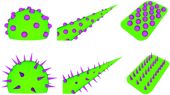
First, we will give the definition of structure units. The structure units have a simple geometry, e.g. cubic, cylinder and sphere, and serve as basic elements to make up one-level solid structures. Each unit has three characteristic lengths along its three natural geometrical directions, denoted as a, b and c respectively. Without loss of generality, we assume that a ≥ b ≥ c. The aspect ratio of a unit can be defined as 1:(b/a):(c/a). When it is close to 1:1:1, this structure unit can be regarded as zero-dimensional (0D). When a is much longer than b and c, corresponding to an approximate aspect ratio of 1:0:0, it is defined as a one-dimensional (1D) unit. Similarly, when a and b are much larger than c, it is a two-dimensional (2D) unit. For examples, spherical dots and particles,93 fibers and tubes,94 disks and platelets95 are normally regarded as 0D, 1D and 2D structures.
In materials science, the classification method based on the concept of dimensionality has been commonly used for structured materials.94,96 Considering crystalline forms and chemical compositions, Gleiter introduced a dimensionality classification scheme of nanostructured materials (NSMs), which contains 12 classes in total.96,97 Pokropivny applied a similar scheme to further divide NSMs into 36 classes.96,98 Their methods work for the microstructures of bulk materials. Since the wetting property relies mainly on surface morphologies rather than interior bulk structures, the morphological classification is introduced in our paper to describe the features of surface structures. Surface structures constructed with 0D, 1D and 2D units will be referred to as 0D, 1D and 2D structures, respectively, regardless of regularity of the distribution of these units on the surface. For example, a structure consisting of only slender structure units (e.g. micropillars) will be referred to as 1D.
In addition, porous, randomly structured or irregular surface morphologies are also widely observed both in natural and artificial materials. For a surface structure consisting of highly inter-connected units with intimate interfaces, whether it be dot-, wire- or plate-shaped, it may not be appropriate to simply fit it into 0D, 1D or 2D classes. In this paper, this kind of structures is referred to as 3D.99 For example, when particles, fibers and/or platelets are assembled into a spatial network or porous structure on a solid surface, it will be referred to as 3D.
Almost all superhydrophobic biological tissues and artificial surfaces can be categorized into the above classification, as we will show in Sections 3 to 5. It has to be noted that sometimes the boundaries for the different dimensional classes may not be very distinct. To better illustrate the four dimensional classes from 0D to 3D, representative biological materials for each class will be given in Sections 3.2–3.5.
3.2. Examples of 0D surface structures
Lotus leaves are a well-known example of biological materials with superhydrophobicity. Early researchers had speculated that surface roughness and microscopic morphology might significantly affect the wetting property of lotus leaves.100 In 1997, Barthlott and Neinhuis made the first SEM observation of lotus (Nelumbo nucifera) leaf and directly confirmed the significant contribution of roughness to its superior water-repellency.15,101 They found that the upper surface of a lotus leaf is made of epicuticular wax crystalloid and micropapillae (Fig. 4(b)). Owing to the combined effects of microstructures and chemical compositions, the surface possesses a 160.4° water contact angle with superior non-adhesive and slippery properties. Water droplets on lotus leaves can roll off effortlessly, bringing dust particles away. To exam this self-cleaning property, different kinds of plant leaves were contaminated and then subjected to water droplets. In contrast to the 5–50% dust particle retention on microscopically smooth leaf surfaces, the microscopically rough lotus surface kept itself almost completely clean.15 Later, Feng et al. showed that lotus leaves have hierarchical structures at the micrometer and nanometer scales. They found that the micropapillae have an average diameter ranging from 5 to 9 μm, while each papilla has branch-like nanostructures with a diameter of ∼124 nm. Both the micro- and nanostructures were believed to have promoted the superhydrophobic wettability of lotus leaves.102 Gao et al. further confirmed that the second-level structure mainly contributes to increase of the receding angle thereby eliminating the contact angle hysteresis.103
|
| Fig. 4 (a) An optical image of the surface of a lotus leaf and (b) an SEM image of micropapillae on a lotus leaf.2 SEM images of sphere-shaped micropapillae (c) on a red rose petal16 and (d) a taro leaf.104 Reprinted from ref. 2, 16 and 104 with permission. | |
According to SEM images, micropapillae, which can be regarded as sphere-shaped units, are distributed on the lotus leaf surface. Thus, lotus leaves have 0D surface structures at the micrometer scale (Fig. 4(b)). Similar morphologies also exist on many other natural surfaces with superhydrophobic properties, e.g., red rose petals (Fig. 4(c)) and taro leaves (Fig. 4(d)).104 On red rose petals, the micropapillae have an average diameter and height of 16 μm and 13 μm, respectively. Taro leaves also are composed of spherical units, with both the average diameter and height of microstructure units being around 13 μm. These plant tissues share a similarity that the aspect ratios of their structure units are around 1:1:1 and can be categorized as 0D structure units. With these sphere-like units, both red rose petals and taro leaves exhibit superhydrophobicity with the apparent contact angles of 152° and 159°, respectively.
3.3. Examples of 1D surface structures
Besides plant tissues such as leaves and petals, aquatic animals living on water surfaces of ponds and lakes also depends crucially on superhydrophobicity. For these insects, locomotion on water surface is especially important. Therefore, in addition to having a large apparent contact angle to support their bodies, a sufficiently large coefficient of friction between the legs and the water surface is necessary to ensure their rapid start and braking of movement.91,105 For example, water striders can swiftly walk and jump on water, which is enabled by the robust water-repellent property of their hairy legs with a contact angle of about 168°.17,106 It was measured that a single water strider leg can produce a supporting force of ∼1.52 × 10⁻³ N, almost 15 times the total body weight.106 Much experimental and theoretical effort has been directed towards understanding how this leg can produce such a big supporting force.107–113 Through theoretical analysis, Feng et al. pointed out that hierarchical surface structures makes a dominant contribution to this superhydrophobic property, since the intrinsic contact angle of leg surfaces is only about 110°.106 SEM images showed that the leg is covered by thousands of microscopically hydrophobic setae. The needle-like setae have an average diameter of 3 μm, length of 50 μm, and inclined angle of 20° measured from the longitudinal direction of the leg (Fig. 5(b)). In addition, finer nanostructures of about 100 nm in depth and 410 nm in width are superposed on the surfaces of microsetae. The nanogrooves further reduce the liquid–solid contact area and enhance the superhydrophobicity, as predicted by eqn (9).106 These groove-like nanostructure units share a similar shape with 1D fibers. However, the convexity of grooves and fibers are different, which will be discussed in detail in Section 4.1. Furthermore, it is worth noting that for such small objects as water strider legs, the elastic strain energy of a solid structure induced by the liquid–solid interaction is comparable to surface energy. In this case, the coupling effect of elasticity and capillary, referred to as elastocapillarity, may play a key role in the wetting behavior and should be taken into account.110,114–118 Ji et al. analyzed the elastic deformation of a walking water strider leg induced by the surface tension of water.113 They demonstrated that this flexibility can benefit the maximal buoyancy of water strider legs.119
|
| Fig. 5 (a) A water strider walking on a water surface and (b) an SEM image showing the nanogrooves on strider's seta.106 (c) Curved microhairs on the surface of a Galerucella nymphaea elytron90 and (d) pillar-shaped structure on a cicada wing.120 Reprinted from ref. 90, 106 and 120 with permission. | |
Besides the setae on water strider legs, 1D structure units are also found to prevail in surface morphology of many other natural materials with water-repellent property, e.g. Galerucella nymphaea elytra and cicada wings (Fig. 5(c) and (d)). The elytra of Galerucella nymphaea have long curved setae of about 4 μm in diameter, 70 μm in length, and 33 μm in average spacing. These hairs render the surface with a contact angle of 159 ± 7° and ensure the stability of air bubbles inside their spacing for underwater breath.90 Similar to the needle- and hair-like structures on water strider legs and nymphaea elytra, the surfaces of cicada wings (Fig. 5(d)), with a contact angle greater than 150°, have pillar-shaped units with an average diameter of 50 nm and height of 250 nm.120 The three above types of 1D structure units of water strider legs, Galerucella nymphaea elytra, and cicada wings share the similarity that their heights are much larger than the diameter, with corresponding aspect ratios of 10, 10 and 5, respectively.
3.4. Examples of 2D surface structure
For some insects, water droplets condensed on their bodies may be adverse for their biological activities, e.g., flight stability. Superhydrophobic properties are crucial for them to eliminate undesired water condensation. The butterfly wings (Morpho aega) have a direction-dependent water rolling resistance.18,121,122 Although the surface has a contact angle of 152 ± 1.7°, water droplets would only roll along the radial outward direction of the wing. Experiments showed that droplets start to roll off in the radial direction when a 9° tilt angle is applied, but the droplets are pinned tightly even when the wing surface is tilted vertically in the opposite direction.18 SEM images revealed that the wings are covered with a large number of unidirectionally oriented quadrate scales, with 150 μm in length and 70 μm in width. On each microsized scale, multi-layers of cuticle lamellae are stacked stepwise with 184.3 ± 9.1 nm in width and 585.5 ± 16.3 nm in clearance (Fig. 6(b)). This finding suggests that the anisotropic wetting property of the wing may be caused by its directional array of structures consisting of microsized scales and nanosized stripes, which are all oriented in the radial outward direction of the wing. Therefore, a three-phase line with less contact length would be formed with air pockets trapped in the nanogrooves when droplets are moving along the radial direction. With this superhydrophobicity-based function, water droplets can be easily removed from the wings, ensuring the flight stability. Achieving directional movements of water droplets in microdevices and systems is of technological interest in the fields of medical engineering, water harvesting, etc. The structures observed in these natural materials may provide inspirations for designing novel devices with directional water collection and transport functions.
|
| Fig. 6 (a) A butterfly122 and (b) the microsized scales covered with lamella-stacking nanostripes on its wing.18 (c) Round-edge microsized scales on a mosquito leg123 and (d) serrated-edge scales on a moth wing.124 Reprinted from ref. 18 and 122–124 with permission. | |
Many other biological tissues also possess 2D or plate-shaped surface microstructures. For instance, Fig. 6(c) and (d) show the structures of mosquito legs and moth wings, respectively. Mosquito legs are covered with an ordered array of round-edge microsized scales, which are typically about 15 μm in width, 40 μm in length, and 250 nm in thickness. The mosquito legs have a contact angle of about 153° and can produce a surprisingly high water-supporting force, ∼23 times the total body weight.123 As another kind of two-dimensional structure units, serrated edge scales render the moth (Catocala electa) wings with a contact angle of about 145°.124 The characteristic sizes of the moth scales were measured to be 454 μm in length, 154 μm in width, 314 nm in thickness, and 343 nm in clearance. The geometrical data of the scales on the butterfly wings, mosquito legs and moth wings show that these units all possess large width–thickness ratios. Therefore, they can be categorized into the 2D microstructure class.
3.5. Examples of 3D surface structures
As an angiosperm plant, ramee lives in areas with rich rainfall. Guo et al. found that a ramee leaf has drastically different wetting properties on its two opposite faces.104 The frontal surface is hydrophilic, with the contact angle of only 38 ± 2°, while the rear surface is superhydrophobic, with the contact angle of 164 ± 2°. This difference was proposed to originate from the different morphologies on the two surfaces. The frontal surface is covered by a sparse web of microfibers with sphere-like microsized structure units inside the intervals. The surfaces of these microfibers are smooth, without finer structures. In contrast, the rear surface is covered by randomly arranged thread of long fibers with diameters about 1 to 2 μm. The microfibers on the rear surface generate a three-dimensional porous structure and greatly decrease the solid–liquid contact area. In addition, the microfiber is further decorated with grooves, rendering a hierarchical structure (Fig. 7(b)). Over the past years, considerable attention has been drawn to fabricating biomimetic surfaces that utilize long fibers to increase their superhydrophobicity.125 The electrospinning method, which will be discussed in Section 5.8, is often adopted to produce fibrous materials.126
|
| Fig. 7 (a) A photograph of a ramee leaf and (b) the microfibers with finer grooves on its rear leaf surface (the inset demonstrates its high water-repellency).104 Porous microstructures of (c) a perfoliate knotweed rear surface,104 and (d) a spider silk.127 Reprinted from ref. 104 and 127 with permission. | |
3D surface structures also exist in many other biological tissues. For example, Fig. 7(c) shows a perfoliate knotweed rear surface, which possesses a porous structure constructed by long microfibers.104 The large fraction of trapped air renders the surface with a good self-cleaning property. Although not superhydrophobic, the spider silk utilizes its porous surface structures to directionally capture water droplets (Fig. 7(d)),127 and the underpinning mechanism of water collection will be discussed in Section 4.2. According to our prior classification, the ramee rear surfaces, perfoliate knotweed rear surfaces, and spider silks can be categorized into the 3D class.
3.6. Discussions
As an idealization, the classification method described above only captures the prominent geometric feature of surface architectures that dominates wetting properties from the viewpoint of dimensionality. In reality, some biological materials have very complex structures and it may be ambiguous to cast them into one of the above-defined dimensionality classes. For example, some structure units have a length comparable to the average width (or diameter). According to the terminology of botany, the epidermal cells with different values of the aspect ratio, defined as β = height/width, are distinguished with different names: convex (β < 2/3), papilla (2/3 < β < 3), hairpapilla (3 < β < 7), and hair (β > 7).45 In this review, a structure is simply named as 0D or 1D when its height-diameter ratio is less or greater than 2, respectively. If a morphology lies in the transition zone between the 0D and 1D classes, the boundary between the two geometrical dimensionalities is somewhat elusive and the functions of the material may also be transitional or hybrid.
Natural surfaces in the same dimensionality class may have distinctly different physical properties and biological functions. To further understand the multiple functions of a biological material, more details about its chemical compositions and geometric structures should be taken into account. For the 0D surface structures, the key geometric parameters may include the average diameter d (or height h) and spacing s of the structure units. The 1D surface structures can contain the following microscopic geometric parameters: length l, diameter d, tilt angle φ, and spacing s of the needle-like units. In the 2D class, the plate-like structures can be further depicted by their thickness t, sizes l1 and l2, average distances s, and tilt angle φ. For a 3D porous structure, its average porosity ρ and the average pore diameter d can be the two other key parameters. These structures together with the corresponding microscopic geometric parameters are summarized in Table 1.
Table 1 Schematic diagrams and possible geometrical parameters for 0D to 3D one-level structures
Dimensionality |
Schematic diagram |
Possible parameters |
0D |
|
Height h, diameter d, distance s |
1D |
|
Diameter d, length l, distance s, tilt angle φ |
2D |
|
Thickness t, length l1, l2, distance s, tilt angle φ |
3D |
|
Average porous diameter d, void ratio ρ |
Though the surface energy and contact angle of a solid surface largely depend on the macroscopically averaged structural parameters, the characteristic shapes and sizes of microscopic structure units also influence its advancing and receding contact angles. The homogenization techniques in the micromechanics of heterogeneous materials, e.g. self-consistent method and Mori–Tanaka method, can be invoked to provide more meaningful estimations of the overall effective surface parameters than the conventional area-average method. The homogenized parameters such as roughness factor r or the solid area fraction f can then be further introduced to an appropriate wetting model (e.g., Wenzel or Cassie–Baxter model) to better estimate the contact angles of structured surfaces.
Another microscopic structural factor that affects the wetting behavior is the arrangement of structure units. For instance, all surface structures of lotus leaves, mosquito eyes, and rice leaves can be classified in the 1D class at the micro scale. However, the dots are randomly distributed on the surfaces of lotus leaves (Fig. 4(b)), regularly packed into a hexagonal pattern on mosquito eyes (Fig. 9(b)), and located along some parallel lines on the upper surfaces of rice leaves (Fig. 9(d)). The three biological tissues, though all superhydrophobic, have some other different wetting-related functions: the lotus leaves have the ability of self-cleaning but without obvious preferred directions of droplet movement, while the mosquito eyes and rice leaves have antifogging and directional water-repellent properties, respectively. More detailed discussions on the relationship between biological functions and structural features will be provided in the next section.
4. Dimensionality classifications of hierarchical surface structures
As discussed in Section 2, hierarchical surface structures may significantly influence the wetting, adhesion, heat transfer, and many other physical properties of surfaces.103,106,128,129 In nature, most living creatures take advantage of hierarchical surface architectures, especially those at the micrometer and nanometer scales, to achieve their wetting-related functions.20,130,131 Based on the definition of one-level dimensionality proposed in Section 3, we will present the morphological classification of hierarchical structures to correlate their geometric morphologies with biological functions.
4.1. Concepts of hierarchical classification
The wetting state of a liquid droplet is determined mainly by the chemistry and surface structures of the contacting solid, especially in a narrow region along the three-phase line.55,78,81,82 The width of the dominating region is typically in the range of nanometers or microns, depending on the characteristic structural sizes.77 In this study, we mainly consider hierarchical structures consisting of two levels, which are at the micrometer (the first) and nanometer (the second) levels, respectively. According to the dimensionality classification defined in Table 1, sixteen types of hierarchical dimensionality can be constructed by combing any two building blocks of 0D to 3D at the two levels, as shown in Table 2.
Table 2 Classification of two-level hierarchical structures
Nano/micro |
0D |
1D |
2D |
3D |
0D |
|
|
|
|
1D |
|
|
|
|
D |
|
|
|
|
2D |
|
|
|
|
3D |
|
|
|
|
Besides the sixteen two-level structures listed in Table 2, we further introduce four additional dimensional classes in which the second-level structures consist of concave nanogrooves with a large length–width ratio. As a concave variant of 1D structure units, the dimensionality of grooves is denoted as D in order to distinguish them from fibers. It is noted that although similar definitions for concave 0D, 2D and 3D structures can be introduced, these structures will not be discussed in this review because of there are not commonly found in superhydrophobic biological tissues.
Groove structures are often observed in the second-level structures on hierarchical surfaces of biological tissues. A few examples are shown in Fig. 8, including micropapillae of rose petals,16 fibers of silver ragwort leaves,19 tomenta of duck feathers,132 and cactus spines.88 The grooves can further roughen the solid surfaces and enhance superhydrophobicity. Groove structures are also frequently observed other tissues, e.g., flower leaves (petals), seed surfaces,2 and insect hairs.90 It was suggested that these concaved patterns, e.g. the grooves on the flower petals, are produced through a mechanical buckling process.133
|
| Fig. 8 SEM images of (a) the cuticle folds on a micropapilla of a red rose petal,16 (b) the aligned grooves on a spine of cactus,88 (c) the grooves on a fiber of a silver ragwort leaf,19 and (d) the textures on a tomenta of a duck feather.132 Reprinted from ref. 16, 19, 88 and 132 with permission. | |
|
| Fig. 9 Optical and SEM images of various biological surface structures with superhydrophobic functions. (a) A mosquito134 and (b) the nanonipples on its compound eye surface.4 (c) A rice plant8 and (d) the directionally arranged micropapillae on its leaf surface.104 (e) A desert beetle and (f) the flattened hemispheres on its elytra.87 (g) A gecko140 and (h) the nanosized branched spatula on its toe.21 (i) A cranefly145 and (j) the grooved hairs on its wing.144 (k) A Chinese watermelon and (l) the long microfibers on its surface.104 These biological tissues can be categorized into Classes (0, 0), (0, ), (0, ), (1, 1), (1, ) and (3, ), respectively. Reprinted from ref. 4, 8, 21, 87, 104, 134, 140, 144 and 145 with permission. | |
To better classify the two-level hierarchical surface structures, we will introduce a dimensional notation. In this paper, the dimensionality of a two-level surface architecture is depicted by a pair of indices (i, j), with i, j = , 0, 1, 2, 3 representing the dimensionalities of micrometer and nanometer structures, respectively.
However, only certain dimensional classes of hierarchical surface structures are commonly observed in biological materials. For example, some typical creatures are listed in Table 3, which include plant leaves, plant petals, reptile feet, insect wings, insect elytra and other biological tissues. In the following, we will discuss a few representative classes of biological surfaces.
Table 3 Hierarchical biological materials classified by morphological dimensionality
Nano/micro |
0D |
1D |
2D |
3D |
0D |
Mosquito compound eye4 |
|
|
|
1D |
Lotus leaf,102 rice leaf,102,104 thunberg wing131 |
Toe of the gecko foot21,141,142 |
Butterfly wing18 |
Perfoliate knotweed leaf104 |
D |
Rose petal,16 desert beetle elytron87,136 |
Water strider leg,17,106 cranefly wing,144 duck feather,132,146 backswimmer elytron,90 dragonfly wing147 |
Mosquito leg123 |
Silver ragwort leaf,19,148 ramee rear leaf,104 Chinese watermelon skin104 |
2D |
Peanut leaf,137 bamboo leaf,139 Euphorbia myrsinites leaf138 |
|
|
|
3D |
|
|
|
|
4.1.1. Class (0, 0). Fig. 9(a) and (b) show an optical image of mosquito134 (C. pipiens) and the surface structure on its compound eye. The compound eye is composed of microsized hemispheres with an average diameter of 26 μm.4 Each of these hemisphere is covered with a nanosized 0D structure, which is made up of thousands of nipples with an average diameter of 101.1 ± 7.6 nm and spacing of 47.6 ± 8.5 nm. The elegant hierarchical structure endows the surface with excellent superhydrophobicity and antifogging function. Even in a very humid environment, mosquito eyes can keep dry and clean.4
4.1.2. Class (0, 1). Lotus (Nelumbo nucifera) leaves, rice (Oryza sativa) leaves, and thunberg wings belong to this class. The microstructure of lotus leaves has been described in Section 3.2. Under a higher magnification, randomly arranged nanosized structures can be found on the micropapillae of lotus leaves. The units of the second-level structure have a 1D pillar-like shape and random orientations, which eliminates the directional dependence of the micropapilla surfaces. Since the two-level nanostructure is believed to possess a high efficiency to enhance superhydrophobicity, the surface structure of lotus leaves has been imitated and incorporated in many bioinspired or biomimetic materials.39,135The rice leaves (Fig. 9(c)) have an anisotropic wetting property: the sliding angle is 4° along the leaf vein direction but it is 12° along the perpendicular direction.102 This property is attributed to the directional arrangement of 0D micropapillae along straight lines in the vein direction (Fig. 9(d)). The SEM images show that every micropapilla has a finer hairy nanostructure and the hairs have an average diameter of ∼4 μm and an average spacing of ∼300 nm.
Similarly, the thunberg (Acrida cinerea cinerea) wing is covered with randomly oriented nanohairs on microsized 0D hemispheres,131 rendering a contact angle of 151°. Each hemisphere is about 7 μm in diameter, and the average spacing of its nanohairs is about 150 nm.
4.1.3. Class (0, ). Two examples in this class are the petals of red rose (rosea Rehd) and the troughs of desert beetle elytra (Stenocaraare, from Namib Desert). In 2008, Feng et al. reported an adhesive superhydrophobic state, which seems to conflict with the common concept that a superhydrophobic surface is usually non-sticky to water. They named this phenomenon as ‘petal effect’, which has a big difference from the well-known self-cleaning ‘lotus effect’.16 When a water droplet is placed on the red rose petal, the petal exhibits a water-repellent property with a contact angle of 152.4°. However, if the petal surface is turned upside down, the water droplet can be still pinned, indicating a strong adhesive property of the surface. SEM images show that the structures on the petal are made up by a combination of 0D (the first level) and D (the second level) units. The former consists of an array of papillae of ∼16 μm in diameter and ∼7 μm in height, while the latter is made up by nanowrinkles with a width of ∼730 nm (Fig. 8(a)). Such a hierarchical structure helps to form an impregnating Cassie state, which improves the adhesive property of the rose petal surface. Koch et al. showed that the wrinkles on the flower surface might create a favorable environment for insect pollinators to climb and walk.45Desert beetles (Fig. 9(e)) living in desert are well known for their peculiar capability of water collection. Due to the capillary effect, droplets formed on the top of the elytra of a beetle will roll automatically towards its mouth.29,136 The elytra are covered with an array of bumps consisting of hydrophilic parts on their peak and superhydrophobic parts on their trough. The superhydrophobic trough is covered with 0D flattened hemispheres, which have nanosized D grooves (Fig. 9(f)). The average diameter of the hemispheres is about 10 μm and the average width of the nanogrooves is about 150 nm. The gradient of the surface wetting property drives water droplets to move directionally.
4.1.4. Class (0, 2). In Class (0, 2), we include three examples here, e.g. the leaves of peanut (Arachis hypogaea), spurge (Euphorbia myrsinites), and bamboo (Phyllostachys pubescens). The peanut leaves have both strong adhesion and superhydrophobicity.137 SEM images show that their leaves are covered with microsized bumps, on top of which nanoplatelets are randomly dispersed as the second-level structure. The adhesion between a 4 μL water droplet and a peanut leaf is measured to be larger than 70 μN, although the static contact angle is greater than 150°.A similar hierarchical structure was found by Koch et al. on the Euphorbia myrsinites leaves, which consists of a combination of regularly distributed and microsized convex cells and nanosized wax platelets. The surface has a contact angle of 157°.138 Both the average diameter and height of the first-level 0D micropapillae are about 20 μm. The platelets are randomly arranged on the convex bumps, having an average thickness of ∼40 nm and width of ∼1 μm.
The self-cleaning property is found on bamboo leaves that has a hierarchical (0, 2) structure.139 The micropapillae on bamboo leaves are ∼5 μm in diameter and ∼7 μm in lateral spacing. Nanoplatelets, about 100 nm in thickness and 700 nm in width, are dispersed on the micropapillae, without a preferential direction.
4.1.5. Class (1, 1). Geckos (Fig. 9(g)) are able to effortlessly climb on both smooth (e.g. glass windows) and rough (tree barks).140 The images in Fig. 9(h) shows the hierarchical surfaces of a hairy toe of Tokay gecko (Gekko gecko). Each toe is covered with about half million keratinous seta of 30–130 μm in length and 1–2 μm in diameter.141–143 Each microseta is further branched into a few hundreds of spatula-shaped nanohairs of 100–200 nm diameter. Liu et al. found that the toes of gecko feet are not only highly adhesive but also superhydrophobic.21 Duplicated polyimide films of gecko feet were measured to have a contact angle of about 150°. They also reported a phenomenon like the ‘petal effect’: water droplets can be pinned on the surface, indicating a strong adhesive ability.
4.1.6. Class (1, ). A few examples of Class (1, ) are cranefly (Nephrotoma australasiae) wings, duck (Anatidae) feathers, backswimmer (Notonecta glauca) elytra, water strider (Gerris remigis) legs, and dragonfly (Libellula basilinea McLachlan) wings. The cranefly wings is superhydrophobic and has a contact angle of over 170°.144,145 Its surface, except the boundary regions, are covered by uniformly distributed hairs of 12 ± 1.5 μm in length and 14 ± 2 μm in spacing, as shown in Fig. 9(j). Similarly to the hierarchical structure on water strider legs described in Section 3, the hairs have grooves as the second-level structure, with an average width of ∼400 nm.The branch of duck feathers is made of fine tomenta with nanosized D grooves and protuberances.132,146 Using the Cassie–Baxter model, the air fraction inside the feather surface was estimated as high as 85–97%.
Backswimmer is an aquatic insect that can carry an air film when submerged in water. The retained air film can keep it ‘dry’ under water for more than 120 days.90 On its elytra, the wire-like 1D units have two different sizes.90 The larger hairs, also named seta, are about 31 μm in height, 3.1 μm in diameter, and 81 μm in spacing. SEM images show that the setae are further roughened by second-level D grooves of 300 nm in width. In addition to the seta, smaller hairy units, called microtrichia, are distributed in the space between thicker hairs. Balmert et al. proposed that the thicker microsetae can stably carry a larger volume of air for a relatively short time while the smaller and denser hair microtrichia retain a less volume for a longer period.
A dragonfly wing possesses a large contact angle of ∼174°.147 The superhydrophobicity is crucial for the dragonfly to fly agilely in the rain and keep its wings clean. Different from the (1, ) structures discussed above, both the first- and second-level structures of dragonfly wings are at the nanometer scale. The wing membrane is covered by vertical columns, with an average diameter of ∼39 nm, average distance of ∼115 nm, and number density of ∼75 μm−2. The finer grooves on the columns are about 14 nm thick.
4.1.7. Classes (2, 1) and (2, ). Butterfly (Morpho aega) wings and mosquito legs have hierarchical surface structures of classes (2, 1) and (2, ), respectively. They have been described in Section 3.4.
4.1.8. Class (3, 1). The surface structure of perfoliate knotweed (Polygonum perroliatum L.) leaves, as shown in Fig. 7(c), belongs to Class (3, 1). It possess a porous microstructure with an average distance of ∼25 μm. On this porous microstructure, there are second-level randomly-distributed and branch-like fibers, which are 200–400 nm in diameter and 1–2 μm in spacing.104 Owing to the hierarchical porous 3D structure, the surface has a large contact angle of 163 ± 2°.
4.1.9. Class (3, ). Three examples in this class are silver ragwort (Senecio cineraria) leaves, ramee (Boehmeria iongispica steud) rear leaves, and Chinese (Benincasa hispida cogn) watermelon surfaces. Silver ragwort leaves are densely covered by tangled 1D fibers with a diameter around 6 μm.19,148 The fiber surface is decorated by finer D grooves (∼200 nm in diameter) aligned along the fiber axial direction. The hierarchical morphology grants the silver ragwort leaf the superhydrophobic property with a contact angle of 147°.Both the ramee rear leaf and Chinese watermelon skin exhibit similar microstructures, which consist of long and randomly arranged fibers with an average diameter of ∼2 μm (Fig. 9(l)). As their second-level, the grooves, with an average width of ∼400 nm, greatly increase the air fraction f in the Cassie–Baxter wetting state. The contact angles of ramee rear leaf and Chinese watermelon skin are about 164 ± 2° and 159 ± 2°, respectively.
4.1.10. Other classes. Besides those classes listed in Tables 3 and 4, there are some other types of hierarchical surface structures in nature, which are not included therein because of relatively scare existence. For examples, Purple setcreasea (Setcreasea purpurea boom) leaves104 and Chinese Kafir lily petals16 should be regarded as classes (, 2) and (, ), respectively. On the purple setcreasea leaves, there are concave hexagonal (D) structures with side lengths in the range of 40–60 μm. The microsized hexagons are covered by branch-like nanosized platelets with an average diameter of ∼250 nm. The frontal surface of a purple setcreasea leave has a water contact angle of 167 ± 2°. Similarly, Chinese Kafir lily petals are also featured by close-packed concave hexagons with an average side length of ∼75 μm, which contains many nanofolds as the second-level structure. Though its water contact angle goes as high as ∼150°, the Chinese Kafir petal shows a distinct ‘petal effect’: the droplets can stay pinned on the surface even when the petal surface is turned upside down.
Table 4 Usual functions of biological materials with different dimensional structures
Nano/micro |
0D |
1D |
2D |
3D |
0D |
Antifogging4 |
|
|
|
1D |
Lotus effect,15,102 directional water-repellency102,104 |
Petal effect21 |
Directional water-repellency18 |
Lotus effect104 |
D |
Petal effect,16 water capture87 |
Lotus effect,132,144,147 supporting force,17,106 air plastron90 |
Supporting force123 |
Lotus effect104,148 |
2D |
Lotus effect,138,139 petal effect137 |
|
|
|
3D |
|
|
|
|
4.2. Discussions
Based on the dimensionality classification proposed in Section 2, various representative superhydrophobic biological surfaces are given in Table 3. Their wetting-related properties and functions are summarized in Table 4 in order to gain insights into the structure–function relations. From Table 3, it is seen that for biological materials with superhydrophobicity, 0D and 1D units seems to be more favorable in the first-level structures than the other classes while 1D and D morphologies are more widely observed on the second-level at the nanometer scale. The popularity of these architectures might indicate their advantages over others for the application of superhydrophobic functions. For instance, certain dimensionality of structures may have a higher efficiency such that it can accomplish the same superhydrophobic property with lower requirements for surfaces or materials. As an example, the Lady's Mantle leaves only takes use of hydrophilic (intrinsic contact angle less than 60°) and flexible 1D hairs to generate a good non-wetting property (apparent contact angle about 140°).149,150
The second-level D grooves or folds can be readily created by invoking surface wrinkling. Most biological tissues have multilayered structures, which have different growing rates, leading to residual stresses in the system. When the compressive strain reaches a critical condition, the initially smooth surface may become unstable and wrinkle into ordered or disordered creases or folds.151–155
Besides the geometric features summarized above, we should notice that, for live biological material, its surface morphology does not always stay the same. Instead, it may change under different external stimuli or evolve with time. In addition, the specific morphology of biomaterial depends on various factors, for example, the chemical compositions. For many animal and plant tissues, their surfaces are covered with cuticle, which is hydrophobic and contains epicuticular waxes. The crystal type and mechanical property of the epidermal wax may also have a very significant role in the formation of certain functional morphologies.
5. Functions of different surface structures
Through natural evolution and adaption, many biological materials have adopted optimal surface morphologies with enhanced physical properties and biological functions. Other than helping gain insights into the relationship between the specific functions and geometrical morphologies of biological materials, the proposed classification method in terms of surface dimensionality may also provide clues for the optimal design and fabrication of biomimetic materials with similar functions. More specifically, one can readily select a hierarchical surface architecture for an engineering material to achieve certain desired functions by mimicking the biological materials with similar functions.
In Section 4, several representative biological materials have been categorized according to the dimensionality of their hierarchical surface architectures, and Table 4 provides a functional map for the wetting-related functions of these hierarchical structures. It is noted that besides surface microstructures, some other physical, chemical and biological factors may also affect the functions of biological materials. Despite this, as we have showed in Section 2, the above classification based on the geometrical morphologies can capture the essential key factors that result in a diversity of biological functions. In the following Sections 5.1 to 5.4, we will discuss the main functions listed in Table 4.
5.1. Self-cleaning
Table 4 provides a general linkage between their surface properties and their hierarchical structures. The superhydrophobicity-related functions in Table 4 can be divided into two classes, isotropic (or non-directional) and anisotropic (or directional). For example, the self-cleaning property can either be non-directional (e.g., lotus leaves) or directional (e.g., butterfly wings and rice leaves), depending on the directional features of their hierarchical surface structures.
The anisotropic non-wetting property of a material can be realized by the directional distributions of chemical compositions and/or geometrical structures on its surface.156 For example, among the representative biological surfaces in Table 4, the butterfly wings in Class (2, 1) and the rice leaves in Class (0, 1) have directional self-cleaning or water-repelling property. These anisotropic wetting surfaces have well aligned structures, at least at one length scale (either micro or nano scale). SEM images revealed that the first-level micropapillae on the rice leaves are located along approximately parallel lines. Such an arrangement leads to strongly anisotropic sliding angles: the sliding angle is about 4° along the aligned direction while it is 12° along the perpendicular direction.102,104 On the butterfly wings, both the stripes in the first-level structure and the scales in the second-level structure are oriented in the radial outward direction of the wing, as discussed in Section 3.4.
The geometric dimensionality and dimensions of structure units also contribute to some aspects of the superhydrophobic performance of biological materials. For example, the characteristic sizes of the second-level (nanometer scale) structures are of great importance to stabilize the self-cleaning property under various conditions. The surface of a mosquito eye is able to keep itself dry and clean even when exposed to heavy moisture. The average interparticle spacing of the second-level structure is 47.6 nm, which is smaller than the critical fog condensation diameter (∼190 nm).4 A narrow enough space makes the eye energetically unfavorable for nanosized fog droplets to get trapped or condensed inside the interspaces of the voids. Hence, the superhydrophobic state of the surface keeps stable due to its efficient elimination of water condensation.
With an increase in the second-level structural sizes, a superhydrophobic state may become unstable due to water condensation in the microstructural interspaces, leading to a transition to the Wenzel wetting state. For example, the lotus leaves, which are about 500 nm in the interspace of the second-level structure, are not always superhydrophobic. When the lotus leaves experience a humid environment rather than direct contact with water droplets, water vapors can easily condensate on their surfaces.157 The experiments showed that condensed fog droplets get pinned instead of rolling off with a much reduced contact angle of 74.0 ± 8.5°.157
If the space between structural units continues getting larger, water droplets can be pinned tightly onto the material surface, resulting in the loss of self-cleaning property. Water droplets can easily get into the structure voids (∼730 nm in width) on the rose petal surface and form an impregnating Cassie state, although its apparent contact angle is more than 150°.16 As discussed in Section 4.1.3, a water droplet can stay statically on a petal surface, even when the tilt angle reaches up to 180° (ref. 158) (Fig. 10). As another example, the wings of cicada Terpnosia jinpingensis have a similar adhesive property with a contact angle of about 146°.20 The adhesive force is big enough to retain the water droplets hanging on the wing regardless of gravity, even when the wing is titled 90°. Therefore, the impregnating Cassie state on a petal is greatly different from the Cassie–Baxter state on a lotus leaf though they are both superhydrophobic. In the former case, the wetting state has a larger contact area and thus a sufficiently large adhesive force to pin droplets even when the surface is tilted upside down, referred to as the petal effect. In the latter, the lotus leaf cannot stop an equally sized droplet from rolling down under the same tilt angle, leading to the self-cleaning ability, which is referred to as the lotus effect.
5.2. Water transportation and collection
Water transportation and collection is a major concern in our daily life and some engineering fields. In nature, for many creatures living in arid region, their tissues, such as spider silk and cactus spines, have excellent functions to harvest water. Zheng et al. found that the silk of cribellate spider Uloborus walckenaerius are able to collect and transport condensed water droplets when the environment is humid (Fig. 11(a)). This amazing property is attributed to the presence of two microstructures, namely spindle-shaped knots and wire-shaped joints.127 The spindle-knots have a spherical shape with diameter of 21.0 ± 2.7 μm while the joints are typically smaller, with an average diameter of 5.9 ± 1.2 μm. The periodic distance between the spindle-knots and joints is 89.3 ± 13.5 μm and both of them have porous surfaces. If the joint is regarded as a substrate, the knot part of the silk can be contained in Class (0, 3). The geometrical difference between these two parts can produce two mechanisms to drive the directional movement of droplets. First, the spindle knots are more hydrophilic than the joints, yielding a difference in free energy when a drop contacts the two structures. Second, for a droplet on the spider surface, the sphere-shaped geometry of a spindle knot can produce an extra Laplace pressure along the axial direction of the silk.82,127 The combined effect of the surface energy gradient and the Laplace pressure difference produces a driving force to move the water droplet towards a neighboring knot.
|
| Fig. 11 Images of (a) spider silks127 and (b) a cactus spine.88 Water droplets can be directionally transported and collected by their special geometrical structures. The elytra of beetle Tmesisternus isabellae can be tuned from (c) a golden color into (d) red upon contacting with water.160 Reprinted from ref. 88, 127 and 160 with permission. | |
To survive in the extremely dry environment, the spines of desert cactus can also collect condensed water droplets and transport them directionally. The spines take two key geometrical strategies to achieve this function, as shown in Fig. 11(b). First, the spine surfaces are decorated with two different microstructures, which are the aligned barbs (1D) and grooves (D). The barbs, mainly found in the end part of the spine, are oriented in the direction towards the cactus base. If a droplet starts to move outward of the cactus under external stimuli such as wind or vibration, these barbs can produce a resistant force to prevent this undesired movement. Microgrooves, distributed in the middle part of the spine, have a width varying from ∼6.8 μm near the base to ∼4.3 μm near the tip. According to the Wenzel theory in eqn (3), the gradient of the groove width can generate a contact angle difference. The spine tip is more hydrophobic than its base since the spine skin is covered with hydrophobic waxes. Therefore, this gradient variation in the contact angle can also contribute to the directional movement of droplets. Owing to the combination effects of oriented barbs and grooves, a sufficient driving force can be produced to transport water directionally.88 According to Lu et al.'s observations, the cactus spine surfaces can collect water droplets with a high efficiency: the transportation process of droplets takes only a half to a few minutes.88
Besides cactus spines and spider silks, several species of lizards and Namib Desert beetles (discussed in Section 4.1.3) also have the ability to capture water from the humid moisture.87,89 Dandelion pappus is also known to have a remarkable capability of controlling and transferring water droplets owing to their special conical hairs and fibrous system.159
5.3. Optical functions
Some creatures also utilize hierarchical surface structures to tune the optical appearance of their skins, feathers, wings, etc. For example, the beetles Tmesisternus isabellae change their elytra skin color in response to environmental stimuli by adjusting their unique surface structures without any change in chemical compositions.160 When wetted by water, its hydrophilic elytra can transfer the initial golden color in the dry state to red in the wet state only by geometrical changes in surface structures (Fig. 11(c) and (d)). SEM images revealed that the elytra are made up of microsized scales, which are marked with a series of grooves with a spacing of about 1 μm. Besides, the grooves are further imposed by fine grooves spaced by a width of about 45 nm. According to the dimensionality classification, this surface structure can be categorized in Class (, ). The interior of elytra scales has a multilayered structure consisting of two kinds of alternating layers. When the scales on the elytra gets wet, the thickness of one kind of layers is swelled, while the thickness of the other kind of layers remains nearly unchanged. With the sophisticated surface structure, the wavelength of the reflected light can be tuned from 601 nm in the dry state to 669 nm in the wet state, accomplishing the optical function upon the contact with water.
Many engineering materials are required to have certain optical functions, in addition to wetting-related properties such as self-cleaning. Bioinspired design and fabrication of transparent superhydrophobic materials have attracted considerable attention and have been widely used for engineering applications, e.g., windows, screens, solar panels, and paintings, in recent years. In general, the typical sizes of roughness on the target surface should be no more than 80 nm to avoid the scattering of visible light, which has a wavelength in the range of about 380–760 nm.161
5.4. Water-walking functions
Many aquatic creatures, such as water striders, water spiders, and mosquitoes, possess an outstanding ability to live on water, which is mainly attributed to the hydrophobicity of their legs and the surface tension of water. These creatures usually utilize slender hairs to increase the surface roughness of their moving organs, e.g., legs. These 1D hairs are advantageous in several aspects. First, their superhydrophobic surfaces can carry an air film while submerged in water. This air film not only increases the buoyancy but also helps the respiration of the insects. Some aquatic creatures just breathe the oxygen inside the air bubbles when submerged in water.90,162 Second, superhydrophobicity can help the hairy legs to efficiently reduce the flow drag. Niu and Hu experimentally measured the drag force as a function of the hair length, density, and coating area when a hairy disk was immersed in a soap film. It was found that the hairs can contribute up to a 17% drag decrease compared to that of the bald disk.163 Inspired by these water-walking creatures, man-made robots capable of rowing, leaping off the surface, and climbing the menisci have been reported.164
So far, we have proposed a morphological classification for the hierarchical structures of biological materials by invoking the concept of the geometrical dimensionalities of structure units at different length scales. Thereby, a functional map could be obtained to correlate the multiple functions with the geometric features of surface structures, as shown in Tables 3 and 4. The correlation may help us to take a better strategy when designing artificial materials with required surface properties and functions. Though the present paper mainly addresses wetting-related properties, the dimensionality classification method can potentially be used to study the relation between other surface properties (e.g., adhesion, wear, friction, and acoustics) and the surface structures of materials. In the next section, we will briefly review the physical and chemical methods for preparing hierarchical surface structures.
6. Various fabrication methods for creation of hierarchical surfaces
There is a rising demand in modern industries for advanced materials with multiple functions. Biomimetics or biomimicry of materials aims to take inspirations from natural biological materials to solve intractable problems in materials science and engineering. As discussed above, biological materials often utilize hierarchical structures to achieve their superior physical properties and biological functions. However, since most one-step fabrication techniques can generate only one-level, either micrometer or nanometer scale, surface structures, production of hierarchical surface structures often requires combining two or more techniques. In the past decades, a great multitude of surface patterning methods have been developed to create various surface structures. These include template synthesis,16,165 lithography,52,166 plasma treatment,167 phase separation,168 colloidal assembly,169 chemical vapor deposition,170 electrochemical deposition,171 layer-by-layer deposition,172 sol–gel,173 electrospinning,174 and surface wrinkling,175 which will be briefly described in this section. Some of these methods can produce 0D to 3D and D surface structures at the micrometer scale, and the others can generate 0D to 3D and D structures at the nanometer scale. Their appropriate combinations can create a wide diversity of hierarchical surface morphologies. For more details of these fabrication techniques, the reader may refer to a few recent reviews.42,176–178
In what follows, the dimensionality classification method proposed above will be introduced in the category of biomimetic and artificial surface morphologies. By classifying the biomimetic materials with the same dimensionality as the counterpart biological materials, one can easily choose the fabrication method to produce the desired surface morphologies.
6.1. Template synthesis
Template synthesis is the most widely adopted method to create surface structures at both micrometer and nanometer scales. This technique uses a piece of solid plate with prescribed geometric features as a template. A replica material, e.g. polydimethylsiloxane (PDMS) or other kinds of polymers, is spin-coated or pressed onto the solid template, and then the replica material is cured as a solid film and subsequently removed from the template. Natural biological surfaces can be used as the template for preparing of biomimetic superhydrophobic materials with duplicated surface structures. Biomimetic surfaces like lotus leaves,179 red rose petals16 and taro leaves165 have been obtained using this template method. Artificial surfaces created by other fabrication methods can also be selected as templates.180 Template synthesis can generate various surface morphologies, but challenges still exist in the preparation of an accurate, repeatedly usable, and easily releasable template. Generally speaking, template synthesis can be used to prepare 0D to 3D and D structures.
Yuan et al. prepared a superhydrophobic polystyrene (PS) film with 0D microstructure by the template method (Fig. 12(a) and (b)).165 They replicated a PDMS film (as a negative template) from a fresh taro leaf. Then the PS solution was casted on the negative template, and the taro-leaf shaped PS surface was obtained after solvent volatilization. The obtained PDMS template was used repeatedly to create multiple copies of PS films. The resultant PS surface had a contact angle larger than 155° with pure water, black ink, and fresh blood. Similarly, Sun et al. used the nanocasting technology to duplicate the superhydrophobic PDMS surface from a natural lotus leaf.179 The replica preserved both the 0D microstructure and 1D nanostructure of natural lotus leaves. The contact angle and the sliding angle of the replica were measured to be 160° and 2°, respectively, which are close to those of real lotus leaves. Feng et al. used an anodic aluminum oxide membrane as a template to synthesize aligned polyacrylonitrile (PAN) nanofibers, with a structure similar to that of low-density aligned carbon nanotubes.180 The surface covered with nano 1D PAN fibers was superhydrophobic (water contact angle 173.8°) and oleophilic (rapeseed oil contact angle 26.7°).
|
| Fig. 12 (a) A natural taro leaf surface, and (b) a taro-leaf shaped PS film prepared by using natural taro leaves as the template.165 (c) A array of micropillars fabricated using photolithography and (d) its high magnification image.183 (e) the first-level structures of an artificial surface fabricated by e-beam lithography, and (f) its second-level structures.184 A PTFE surface treated with oxygen plasma for (g) 2 min and (h) 5 min.186 (i) The porous poly-(styrene)-b-poly(dimethylsiloxane) (PS-b-PDMS) surface prepared via the phase separation method and (j) its side view.190 Self-assembly patterns of (k) polydisperse silica spheres and (l) CaCO3–PNIPAM particles.193 Reprinted from ref. 165, 183, 184, 186, 190 and 193 with permission. | |
6.2. Lithography
The lithography technique is developing rapidly to fabricate sophisticated surface patterns at the micrometer and even nanometer scales. Optical lithography (photolithography), X-ray lithography, electron beam (e-beam) lithography, and nanoimprint lithography belong to this novel category.176 Photolithography utilizes light (usually ultraviolet light) to transfer the geometrical information from a photomask to a substrate consisting of light-sensitive materials. Light exposure is followed with several steps of chemical treatments to either retain the pattern on or remove the pattern from the substrate surface. This highly precise method can prepare small patterns down to nanometers in size. X-ray lithography and e-beam lithography share the fundamental principle as photolithography that a high-energy beam (X-ray or electron beam) etches or remains a certain geometric pattern on the target surface. The e-beam lithography does not need a mask since electron beams can be focused to a very fine degree and write the prescribed pattern directly on surface without obvious scattering.176,181 Recently, nanoimprint lithography has appeared as another highly efficient technology, which utilizes mechanical press and heat to replicate a pattern from the master to the replica. A polymer film is firstly heated above the glass transition temperature, and then a stiff master is pressed against it.182 After cooling down the polymer and removing the master, an imprinted pattern is left on the film and the replica is obtained. With lithography methods, regular or even irregular patterns can be prepared with a high precision. Owing to the characteristics of the technique, lithography methods can well produce micro- and nanosized surface structures of D, 0D to 2D. However, lithography methods are limited to mainly produce morphologies on rather flat surfaces and have difficulties to generate porous structures with complexity.
Using the photolithography method, Öner et al. prepared superhydrophobic surfaces with micro 1D posts to study the effect of morphology on the movement of three-phase lines.166 Shirtcliffe et al. reported preparation of micro 1D pillar patterns with diameters ranging from 4 to 40 μm using photolithography. With these patterns, they systematically validated Cassie–Baxter wetting theory (Fig. 12(c) and (d)).183 Fürstner et al. used the X-ray lithography to make hydrophobic silicon specimens with an array of 1D microspikes.52 The width, height, and distance of the microspikes were varied to explore the lotus effect of the artificial substrate. For the above three examples, their micro 1D patterns are all in a ordered arrangement, which share the similarity with the surface structures on cicada wings.20 Feng et al. created hierarchical superhydrophobic surfaces by invoking the dual-scale e-beam lithography method.184 Both the obtained micro- and nanoscale structures can be categorized in Class 0D. The first-level structure was made up of square blocks with dimensions of tens of micrometers, and the second-level structures were distributed over the entire surface with geometrical length ranging from 200 nm to 500 nm (Fig. 12(e) and (f)). Jo et al. used ultraviolet nanoimprint lithography to develop superhydrophobic and superoleophobic surfaces.185 The cone-shaped 1D structure was 2.25 μm in diameter and 1.15 μm in height. Subsequently, ZnO nanorods were grown on the micropattern to enhance the surface roughness and the contact angle.
6.3. Plasma etching
Plasma treatment is a dry etching method that utilizes a high-energetic plasma source (containing either charged ions or neutral atoms) generated by gas discharge. During the etching process, chemically reactive ions from plasma flow are shot towards the target substrate and gradually etch away the materials on the target surface. The plasma treatment method can create deep grooves with steep walls on large scaled surfaces, and sometimes it can be used after lithography or template methods to generate second-level surface patterns. In general, the source gasses of the plasma are required to react well with the surface materials, otherwise the surface patterns would not be realized properly.176
Using this approach, Minko et al. prepared self-adaptive surperhydrophobic surface made of poly(tetrafluoroethylene) (PTFE) (Fig. 12(g) and (h)).186 After the plasma treatment, the originally flat surface was replaced by needle-like and randomly arranged structures. The etched surface had a 1D structure and it showed a contact angle about 160° without an obvious contact angle hysteresis. Mundo et al. fabricated roughened PS films by means of radiofrequency plasmas fed with CF4.187 After random removal of surface atoms, the treated PS samples had a close-packed nano 1D structure with an height ranging from 150 to 600 nm. To enhance the superhydrophobicity, the PS surface was coated by a low-energy fluorocarbon layer through plasma modification. Similarly, Fernandez Blazquez et al. used the oxidative plasma treatment to prepare isolated nanofibrils and fibril bundles on polyethylene terephthalate (PET) films.188 After oxidation treatment, the generated nanofibrils collapsed into bundles with different morphologies. A subsequent perfluorination by gas-phase silanisation rendered the collapsed nanostructure a good water-repellency.
6.4. Phase separation
In phase separation method, a metastable mixture becomes unstable and finally gets separated into two phases, leading to the formation of geometrically or chemically heterogeneous surface patterns. The separation is usually driven by thermodynamic forces (e.g. entropy) under specific environmental conditions of temperature or pressure. If one of the two phases is solidated, a network structure will form with a certain amount of solvent impregnated inside the pores. After removal of the liquid phase, a continuous and porous solid structure can be obtained. This method can prepare complex and irregular morphologies with geometric sizes ranging from nano- to macro-scales.189 Due to its working mechanism, this method is often related to the sol–gel process, which will be discussed later. Besides, the phase separation method can also work together with other techniques, e.g. plasma treatment and electrospinning processes.176
Zhao et al. demonstrated the preparation of poly-(styrene)-b-poly(dimethylsiloxane) (PS-b-PDMS) copolymer with superhydrophobicity using a vapor-induced phase separation method (Fig. 12(i) and (j)).190 The prepared surface was covered with 0D interconnected microspheres, leading to an increase of roughness and a resultant contact angle of ∼163.0°. To mimic the self-cleaning performance of lotus leaves, Wei et al. also fabricated fluoropolymer films using a phase separation technique.191 Styrene and 2,2,3,4,4,4-hexafluorobutyl methacrylate copolymers were dissolved in tetrahydrofuran, and then the ethanol was added in this solution to induce the phase separation. The prepared surface had a 0D microstructure, rending the material with a maximum contact angle of 154.3°. Wang et al. utilized the phase separation method to prepare methylsilicone resin film with porous surface nanostructures. The fabricated surface was composed of nano 1D particles with diameter ranging from 50 to 100 nm. Besides superhydrophobicity, the film also showed a red-light luminescence.192
6.5. Colloidal self-assembly
With the help of van der Waals interactions or chemical bonding, micro or nano particles can self-assemble into a diversity of structures on solid surfaces.169 When a substrate is covered with a solution containing particles, colloidal assemblages may be formed after the solvent is dried. Therefore, colloid assembly can conveniently produce 0D and 3D surface morphologies at both micrometer and nanometer scales. Besides, this method is sometimes followed by other post-treatment methods, e.g. plasma treatment, to achieve hierarchical surface structures with superhydrophobicity.
Using the colloidal self-assembly method, Zhang et al. created several different morphologies consisting of microspheres made of CaCO3–PNIPAM, silica or PS (Fig. 12(k) and (l)).193 They assembled these 0D particles with different constituents or diameters, to achieve a nanoscopically rough surface. Min et al. reported an assembly of 70 nm silica nanospheres into non-close-packed colloidal crystals over a large surface area.194 Then they used the generated 0D colloidal monolayer as a structural template to pattern nanopillar arrays. The produced surface structure had geometrical and functional similarities to that on cicada wings, and it had a broadband antireflective property and a contact angle of 158°.
6.6. Chemical deposition
Typical chemical deposition methods include chemical vapor deposition (CVD), electrochemical deposition, layer-by-layer deposition, etc. In CVD, a substrate is exposed to gaseous precursors to create desired morphology through deposition by specific chemical reactions. Such CVD methods as plasma-enhanced chemical vapor deposition (PECVD),170 catalyst-assisted chemical vapor deposition (CCVD),195 initiated chemical vapor deposition (iCVD)196 have frequently been used to produce advanced functional materials. In the electrochemical deposition method, the conductive substrate is coated with thin films through an electrolytic process. The aqueous solution containing metal ions is applied with a bias between two electrodes, and then a film can be formed with target ions discharging on the electrode surfaces. In the layer-by-layer method, alternating layers with opposite charges are deposited in sequence on the substrate due to the effects of statistic electric interaction. This technique is spontaneous and stable, and the deposited multilayer thickness can be controlled within molecular precision. However, since the surface structure created by layer-by-layer method is rather flat, which may not be ideal for superhydrophobicity, some additional chemical treatments can be performed to enhance roughness and water-repellency of the surface, e.g., introducing nanoparticles.
By using the PECVD method, Lau et al. deposited a carbon forest with vertically aligned 1D nanotubes. With an additional surface coating consisting of poly(tetrafluoroethylene) (PTFE), the advancing and receding contact angles of the obtained materials reached 170° and 160°, respectively.170 Hsieh et al. employed a similar method to decorate carbon nanotubes (CNTs) on carbon fabrics (Fig. 13(a) and (b)).197 Jung et al. reported a superhydrophobic hierarchical structure, in which the nanostructure consisting of CNTs was prepared by CCVD method. This second-level nanostructure is similar to that on lotus leaves, while its first-level structure was made up of 1D micropillars fabricated by a soft lithography method.195 He et al. reported ZnO thin films fabricated on zinc foils with diverse nanostructures by the electrochemical anodization method (Fig. 13(c) and (d)). Different shapes of nanostructures, e.g. nanodots (0D), wires (1D), were obtained by adjusting the reacting time and concentration of the electrolyte.171 Zhai et al. fabricated a honeycomb-like poly(allylamine hydrochloride) (PAH) and poly(acrylic acid) (PAA) multilayer surface coated with silica nanoparticles by using a layer-by-layer method. This surface had microporous (3D) structure with roughness below 100 nm, and it was expected to mimic the behavior of lotus leaves.172 Li et al. produced a highly transparent superhydrophobic coatings (Fig. 13(e) and (f)) through a similar deposition process. These coatings comprised a 3D nanoporous PDDA-silicate/PAA film with dispersed SiO2 nanoparticles on the top of the surface.198 Ogawa et al. prepared electrospun fibrous surfaces coated with fluoroalkylsilane structure to mimic silver ragwort leaves.199 Different numbers of layers of TiO2/PAA were deposited on the membrane surface by the layer-by-layer method. The overall morphology of the prepared surface could be changed with the number of deposited layers. For example, when 5 to 10 layers were deposited, the surfaces of electrospun fibers were modified, which could be regarded as introducing a second-level roughness. However, the fibrous surface could be completely covered leading to a less rough surface, when there were about 30 deposition layers.
|
| Fig. 13 (a) Randomly deposited carbon nanotubes prepared via the CCVD method and (b) its high magnification image.197 ZnO electrochemical anodization grown on the Zn foil with the reaction time of (c) 1 min and (d) 10 min.171 (e) Top view and (f) side view of the (PDDA-silicate/PAA) film deposited on a quartz substrate by the LBL method.198 Gel films deposited on copper wafers with the protrusion diameter in the ranges of (g) 500–700 nm and (h) 1–2 μm.203 (i) Randomly packed electrospun nylon fibers,205 and (j) the wrinkled patterns on electrospun polystyrene fibers.126 Surface wrinkles with (k) zigzag herringbones and (l) random profiles.175 Reprinted from ref. 126, 171, 175, 197, 198, 203 and 205 with permission. | |
6.7. Sol–gel method
In the sol–gel method, a network can be chemically deposited on a target solid surface. The sol is first prepared by hydrolysis and polycondensation of the corresponding precursors in the presence of a solvent and then deposited onto the substrate. After self-assembly of the colloidal particles in the sol, a 3D porous gel will be formed with a large amount of solvent trapped in voids. Thereafter, a drying process is needed to remove the remaining solvent and solidify the network.177 Similar to the phase separation process, nanoparticles are sometimes added into the solvent to enhance the surface hydrophobicity. Surface roughness can be controlled by chemical reactions of precursors.200 Because of its compatibility with glass, the sol–gel progress is particularly favored in creating transparent and superhydrophobic films on glass surfaces.176,201 This technique can readily prepare 3D random and porous structures.
Xiu et al. demonstrated the use of a eutectic liquid in a sol–gel process to produce 3D porous thin silica films with superhydrophobicity. Since the roughness of the prepared surface was only ∼100 nm, the obtained thin films were optically transparent.201 Using a sol–gel deposition method, Rao et al. prepared superhydrophobic copper substrates with 3D microstructures.202 The hydrophobic coating sol was prepared with methyltriethoxysilane (MTES), methanol (MeOH), and water at a specific molar ratio. These coatings were tested to be stable against humidity and mechanically flexible. Fan et al. fabricated a superhydrophobic copper wafer with vinyltrimethoxysilane (VTES), ethanol (EtOH), and ammonia water (Fig. 13(g) and (h)).203 Various surface structures, e.g., pyramid-shaped protrusions and sphere-shaped silica particles, can be obtained on the copper substrate, depending on the reaction conditions and molar ratios of the constituents in the solvent.
6.8. Electrospinning
The electrospinning method has been widely used to produce continuous fibers of microns or nanometers in diameter. In this technique, a polymer solution or melt liquid is contacted with an electrode and the grounded collector. At a sufficiently high electric field, a jet is emitted from a needle and then forms an initial fiber.204 After evaporation of the solvent, the fiber is obtained on the collecting substrate. Electrospinning is often applied with a combination of other chemical or physical methods. To improve the hydrophobicity of the yielded fiber, for example, micro- or nanosized beads can be added in the solution to roughen its surface. In addition, 3D porous microstructures can be formed by randomly oriented fibers collected on a flat or curved substrate.
Utilizing the electrospinning method, Ma et al. fabricated hierarchically structured superhydrophobic fabrics formed by decorating microsized electrospun fibers with nanoscale pores or particles (Fig. 13(i)).205 Xue et al. prepared a superhydrophobic surface with bead-free electrospun fibers made by POSS-PMMA copolymer.206 They found that the microfibers were made up of orderly bundles of second-level nanosized fibers. The fibers produced by Ma et al.205 and Xue et al.206 had a microsized 3D surface structure similar to those on watermelons and ramee rear leaves described in Section 4.1.9. Lin et al. demonstrated the fabrication of superhydrophobic fibrous materials from an electrospinning PS solution in the presence of silica nanoparticles (Fig. 13(j)).126 They created 3D microstructures consisting of randomly oriented microfibers with nanogrooves, similar to those on silver ragwort leaves.
6.9. Surface wrinkling
Surface wrinkling has become a promising method to produce a wide diversity of surface morphologies at the micrometer and nanometer scales. Wrinkles on the surfaces of solid materials are mainly generated by a mechanical instability process, which is usually induced by compressive stresses or stress gradients in the surface layer. Therefore, the essential step in the surface wrinkling technique is to create compressive stresses in the surface layer.
To illustrate the typical wrinkling process, we consider the surface wrinkling of a compliant sheet, say PS or PDMS. The sheet is first elastically stretched to a certain degree such that its strain is larger than a critical value. Then the surface layer of the stretched sheet is modified to have a different elastic modulus than the interior material. This can be accomplished by, for instance, coating a stiff layer or an exposure to ultraviolet-ozone treatment.175,207,208 After forming the stiff surface layer, the pre-stretch is released to generate compressive stresses inside the surface layer which eventually leads to surface wrinkles. The wavelength and amplitudes of the generated wrinkle can be tuned by precisely controlling the thickness and modulus of the modified surface layer.175,209 Under different loading conditions, various wrinkle morphologies can be obtained, e.g., sinusoidal, hexagonal, herringbone, labyrinth, and random profiles (Fig. 13(k) and (l)).210 In addition, since surface wrinkles are generated by elastic instability, the geometrical morphology can be tuned repeatedly by applied loads, leading to actively tunable contact angles and other surface properties. The good tunability and reversibility is a potential advantage over other preparation methods of surface morphology.
Chung et al. examined the wettability of rough surfaces with parallel sinusoidal surface wrinkles.207 Since the surface morphology was anisotropic, the liquid–solid contact region was no longer axisymmetric and the contact angle showed two different values along the perpendicular and parallel directions of the wrinkles. The wavelength and amplitude of the wrinkles were observed to have a greater influence on the contact angle in the perpendicular direction than that in the parallel. It was also found that the wrinkled microstructure had a fully reversible wettability, when it was subjected to cycling loads of uniaxial compression–tension. Lin et al. reported a superhydrophobic surface with dual-scale roughness by coating silica nanoparticles on PDMS wrinkles.208 This hierarchical structure, which is in Class (, 0), can guarantee the Cassie wetting state, resulting in a significant reduction in sliding angle compared with the one-level structure. Combining the nanoimprint lithography method and the surface wrinkling process, Li et al. reported a superhydrophobic surface with a contact angle over 160°.211 The wettability of a surface with herringbone wrinkles can be tuned from hydrophobic (∼130°) to superhydrophobic (∼155°) by increasing the film thickness. Recently, Wang et al. studied the surface wrinkling in a film–substrate system with periodic interfacial microstructures.209 They observed several novel surface wrinkling patterns, e.g., parallel and periodic tilted sawteeth, and alternating upward–downward arcs, depending on the mechanical and geometric parameters of the system. The results are summarized in a phase diagram, which may guide realization of various surface patterns to achieve advanced functions, e.g. blazed grating, anisotropic friction and adhesion, and directional self-cleaning.
6.10. Classification of preparation methods
To illustrate the surface morphologies produced by each preparation method discussed above, representative images are given in Fig. 12 and 13, and a dimensionality classification is summarized in Table 5. Since the dimensionality classification of the preparation methods is not intended to be exhaustive, more methods can be added later in the table.
Table 5 Preparation methods and the morphological dimensionalities of the obtained surface structures
Dimensionality |
Preparation method |
Micro 0D |
Template synthesis,16,165,179 lithography,105,185 phase separation,190,191 and sol–gel203 |
Micro 1D |
Template,180 lithography52,166,183 and plasma treatment186 |
Micro D |
Surface wrinkle207,208,211 |
Micro 2D |
|
Micro 3D |
LBL,172 sol–gel,201–203 and electrospinning126,205 |
Nano 0D |
Colloidal self-assembly,193,194 and lithography184 |
Nano 1D |
Template,165 plasma treatment,187,188 and CVD170,195 |
Nano D |
Electrospinning126,206 |
Nano 2D |
|
Nano 3D |
Phase separation,192 CVD,197 and LBL198,199 |
With the geometrical classification of both biological tissues and preparation methods, one can follow the logic of Fig. 14, and easily determine which preparation methods can be used to fabricate the necessary surface architecture to obtain desired functions that mimic the biological materials in nature: in the first step, the required functions of the engineering material need to be identified. Then, based on the desired functions, one can find from Table 4 the corresponding dimensionality classes that possess the expected functions. Finally, a proper fabrication method can be selected by using Table 5 to prepare the biomimetic materials with the desired functions. As an example, to design a material with directional water-repellency, one can combine the 0D microstructure and the 1D nanostructure by referring to the hierarchical structure of rice leaves (Table 3 and 5). It is known from Tables 3 and 5 that such a biomimetic functional material can be fabricated by using the lithography method and the CVD method to produce the first- and second-level structures, respectively.
|
| Fig. 14 Morphological dimensionality as a guiding tool for the design and fabrication of biomimetic materials with required surface properties. | |
7. Conclusions
The physical properties of a solid surface depend strongly on its chemical compositions and geometrical morphology. Most biological materials take the strategy of hierarchical structures to achieve their multiple surface functions, e.g. superhydrophobicity, water collection and transport. It is of extensive interest to establish the interrelations of the biological functions, physical properties, chemical compositions, and geometric structures of biological materials. To this end, we have proposed a classification method in terms of the morphological dimensionality of structure units at different length scales. The structure units on each level are classified into 0D, 1D, 2D, and D according to their prominent geometric features. Thereby, a hierarchical surface structure can be easily described by considering their features at multiple length levels.
The concept of morphological dimensionality is first used to correlate the biological functions and surface structures of biological materials, and then extended to the design and fabrication of biomimetic materials. Following the proposed functional map, one can easily choose the techniques to produce the desired surface structures that will possess the required functions. In the present paper, our attention has been focused on the wetting-related properties of materials but the proposed classification method can provide potential guideline for tuning other surface properties, e.g., adhesion, friction, heat transfer, and acoustics. This method can also be extended to study the interior structures of biological materials and their correlations with biological functions.
Finally, it is worth mentioning that due to the complexity and diversity of the physical processes in a real-world surface, there are some other factors that affect the wetting-related functions, e.g., elastocapillarity, electrostatics, and self-adaptive mechanisms, which have not been discussed in this paper. In addition, there are a number of topics that deserve systematic exploration. First, most biological materials utilize their surfaces to accomplish a large number of functions. Some functions may, to different extends, have mutual constraints towards each other. On one hand, the morphology of natural materials could be a result of compromising some different functions, and, on the other hand, living materials have some fantastic strategies to achieve some apparently competing properties. To avoid simple replication of biological materials, therefore, one should understand the intrinsic physical mechanisms of natural optimization. To date, it is a challenging issue to fabricate advanced biomimetic materials that have multiple functions as well as those in biological materials. Second, materials with fixed wetting-based functions cannot meet the engineering demands in many applications. Recently, extensive efforts have been directed toward developing materials with reversibly switchable wettability. For example, the reversible switching wettability between superhydrophobicity and superhydrophilicity can be used in the field of directional water collection and transfer. The wetting ability can be reversibly driven by different kinds of physical or chemical stimuli, such as pH level, light, temperature, electrical and magnetic fields.212 Besides, mechanical methods (e.g., wrinkling-based methods) have also attracted considerable attention to tune the wetting property of solid surfaces. Third, superhydrophobic materials used in practical applications, e.g., self-cleaning windshields, anti-fogging glasses, and anti-biofouling paints, should have stable wetting-based functions in service. Although a variety of superhydrophobic coatings have been fabricated with different techniques, it is still hard to keep their high performance of functional surfaces for a sufficiently long period. For biological tissues, the self-healing ability is one of the inherent characteristics to provide an effective way to resolve this problem. Therefore, the design and preparation of bio-inspired and biomimetic materials with self-healing surface property is another promising field with growing interest.
Acknowledgements
Financial supports from the 973 Program of MOST (2013CB933003 and 2012CB934001), the National Natural Science Foundation of China (Grant No. 11432008 and 11372162), and Tsinghua University (20121087991) are acknowledged.
References
- D. Tian, Y. Song and L. Jiang, Chem. Soc. Rev., 2013, 42, 5184–5209 RSC.
- K. Koch, B. Bhushan and W. Barthlott, Prog. Mater. Sci., 2009, 54, 137–178 CrossRef CAS PubMed.
- M. Im, H. Im, J. H. Lee, J. B. Yoon and Y. K. Choi, Soft Matter, 2010, 6, 1401–1404 RSC.
- X. Gao, X. Yan, X. Yao, L. Xu, K. Zhang, J. Zhang, B. Yang and L. Jiang, Adv. Mater., 2007, 19, 2213–2217 CrossRef CAS PubMed.
- P. Kim, T. S. Wong, J. Alvarenga, M. J. Kreder, W. E. Adorno Martinez and J. Aizenberg, ACS Nano, 2012, 6, 6569–6577 CrossRef CAS PubMed.
- Y. Chen, L. Wang, Y. Xue, L. Jiang and Y. Zheng, Sci. Rep., 2013, 3, 2927 Search PubMed.
- K. Fukuda, J. Tokunaga, T. Nobunaga, T. Nakatani, T. Iwasaki and Y. Kunitake, J. Mar. Sci. Technol., 2000, 5, 123–130 CrossRef.
- J. Genzer and K. Efimenko, Biofouling, 2006, 22, 339–360 CrossRef CAS PubMed.
- L. Kunst and A. Samuels, Prog. Lipid Res., 2003, 42, 51–80 CrossRef CAS.
- K. Koch and H. J. Ensikat, Micron, 2008, 39, 759–772 CrossRef CAS PubMed.
- W. Barthlott, C. Neinhuis, D. Cutler, F. Ditsch, I. Meusel, I. Theisen and H. Wilhelmi, Bot. J. Linn. Soc., 1998, 126, 237–260 CrossRef PubMed.
- H. J. Ensikat, M. Boese, W. Mader, W. Barthlott and K. Koch, Chem. Phys. Lipids, 2006, 144, 45–59 CrossRef CAS PubMed.
- Y. P. Zhao, Physical mechanics of surfaces and interfaces, Science Press, Beijing, 2012 Search PubMed.
- T. Nishino, M. Meguro, K. Nakamae, M. Matsushita and Y. Ueda, Langmuir, 1999, 15, 4321–4323 CrossRef CAS.
- W. Barthlott and C. Neinhuis, Planta, 1997, 202, 1–8 CrossRef CAS.
- L. Feng, Y. Zhang, J. Xi, Y. Zhu, N. Wang, F. Xia and L. Jiang, Langmuir, 2008, 24, 4114–4119 CrossRef CAS PubMed.
- X. Gao and L. Jiang, Nature, 2004, 432, 36 CrossRef CAS PubMed.
- Y. Zheng, X. Gao and L. Jiang, Soft Matter, 2007, 3, 178 RSC.
- Y. Miyauchi, B. Ding and S. Shiratori, Nanotechnology, 2006, 17, 5151–5156 CrossRef CAS.
- M. Sun, G. S. Watson, Y. Zheng, J. A. Watson and A. Liang, J. Exp. Biol., 2009, 212, 3148–3155 CrossRef PubMed.
- K. Liu, J. Du, J. Wu and L. Jiang, Nanoscale, 2012, 4, 768–772 RSC.
- R. N. Wenzel, Ind. Eng. Chem., 1936, 28, 988–994 CrossRef CAS.
- A. Cassie and S. Baxter, Trans. Faraday Soc., 1944, 40, 546–551 RSC.
- D. Quéré, A. Lafuma and J. Bico, Nanotechnology, 2003, 14, 1109 CrossRef.
- D. Quéré, Rep. Prog. Phys., 2005, 68, 2495–2532 CrossRef.
- D. Quéré, Annu. Rev. Mater. Res., 2008, 38, 71–99 CrossRef.
- M. Nosonovsky, Langmuir, 2007, 23, 3157–3161 CrossRef CAS PubMed.
- G. Whyman and E. Bormashenko, Langmuir, 2011, 27, 8171–8176 CrossRef CAS PubMed.
- Q. S. Zheng, Y. Yu and Z. H. Zhao, Langmuir, 2005, 21, 12207–12212 CrossRef CAS PubMed.
- Q. S. Zheng, C. J. Lv, P. F. Hao and J. Sheridan, Sci. China: Phys., Mech. Astron., 2010, 53, 2245–2259 CrossRef CAS.
- M. Reyssat and D. Quéré, J. Phys. Chem. B, 2009, 113, 3906–3909 CrossRef CAS.
- L. Gao and T. J. McCarthy, Langmuir, 2006, 22, 6234–6237 CrossRef CAS PubMed.
- H. B. Eral, D. J. C. M. 't Mannetje and J. M. Oh, Colloid Polym. Sci., 2012, 291, 247–260 Search PubMed.
- M. L. Blow, H. Kusumaatmaja and J. M. Yeomans, J. Phys.: Condens. Matter, 2009, 21, 464125 CrossRef CAS PubMed.
- F. Varnik, M. Gross, N. Moradi, G. Zikos, P. Uhlmann, P. Muller Buschbaum, D. Magerl, D. Raabe, I. Steinbach and M. Stamm, J. Phys.: Condens. Matter, 2011, 23, 184112 CrossRef CAS PubMed.
- P. G. De Gennes, Rev. Mod. Phys., 1985, 57, 827 CrossRef CAS.
- P. F. Hao, C. J. Lv, Z. H. Yao and F. He, Europhys. Lett., 2010, 90, 66003 CrossRef.
- Q. Wang, B. Su, H. Liu and L. Jiang, Adv. Mater., 2014, 26, 4889–4894 CrossRef CAS PubMed.
- K. Koch, B. Bhushan, Y. C. Jung and W. Barthlott, Soft Matter, 2009, 5, 1386 RSC.
- M. J. Hancock, K. Sekeroglu and M. C. Demirel, Adv. Funct. Mater., 2012, 22, 2223–2234 CrossRef CAS PubMed.
- T. Sun, L. Feng, X. Gao and L. Jiang, Acc. Chem. Res., 2005, 38, 644–652 CrossRef CAS PubMed.
- X. M. Li, D. Reinhoudt and M. Crego Calama, Chem. Soc. Rev., 2007, 36, 1350 RSC.
- Y. L. Zhang, H. Xia, E. Kim and H. B. Sun, Soft Matter, 2012, 8, 11217 RSC.
- P. Wagner, R. Fürstner, W. Barthlott and C. Neinhuis, J. Exp. Bot., 2003, 54, 1295–1303 CrossRef CAS PubMed.
- K. Koch, B. Bhushan and W. Barthlott, Soft Matter, 2008, 4, 1943–1963 RSC.
- T. Young, Philos. Trans. R. Soc. London, 1805, 65–87 CrossRef.
- R. Tadmor, Langmuir, 2004, 20, 7659–7664 CrossRef CAS PubMed.
- C. Furmidge, J. Colloid Sci., 1962, 17, 309–324 CrossRef CAS.
- P. S. Yadav, P. Bahadur, R. Tadmor, K. Chaurasia and A. Leh, Langmuir, 2008, 24, 3181–3184 CrossRef CAS PubMed.
- G. McHale, N. Shirtcliffe and M. Newton, Langmuir, 2004, 20, 10146–10149 CrossRef CAS PubMed.
- E. Y. Bormashenko, Wetting of real surfaces, Walter de Gruyter, 2013 Search PubMed.
- R. Fürstner, W. Barthlott, C. Neinhuis and P. Walzel, Langmuir, 2005, 21, 956–961 CrossRef PubMed.
- H. Nakae, R. Inui, Y. Hirata and H. Saito, Acta Mater., 1998, 46, 2313–2318 CrossRef CAS.
- A. Cassie, Discuss. Faraday Soc., 1948, 3, 11–16 RSC.
- W. Choi, A. Tuteja, J. M. Mabry, R. E. Cohen and G. H. McKinley, J. Colloid Interface Sci., 2009, 339, 208–216 CrossRef CAS PubMed.
- N. A. Patankar, Langmuir, 2010, 26, 7498–7503 CrossRef CAS PubMed.
- A. Lafuma and D. Quéré, Nat. Mater., 2003, 2, 457–460 CrossRef CAS PubMed.
- B. Wang, Y. Zhang, L. Shi, J. Li and Z. Guo, J. Mater. Chem., 2012, 22, 20112 RSC.
- H. J. Butt, C. Semprebon, P. Papadopoulos, D. Vollmer, M. Brinkmann and M. Ciccotti, Soft Matter, 2013, 9, 418 RSC.
- E. Bormashenko, Adv. Colloid Interface Sci., 2014 DOI:10.1016/j.cis.2014.02.009.
- P. Lv, Y. Xue, Y. Shi, H. Lin and H. Duan, Phys. Rev. Lett., 2014, 112, 196101 CrossRef.
- D. Zhu, S. Kinoshita, D. S. Cai and J. B. Cole, Phys. Rev. E: Stat., Nonlinear, Soft Matter Phys., 2009, 80, 12 Search PubMed.
- K. Chung, S. Yu, C. J. Heo, J. W. Shim, S. M. Yang, M. G. Han, H. S. Lee, Y. Jin, S. Y. Lee, N. Park and J. H. Shin, Adv. Mater., 2012, 24, 2375–2379 CrossRef CAS PubMed.
- J. Y. Zeng, N. Xiang, L. Jiang, G. Jones, Y. M. Zheng, B. W. Liu and S. Y. Zhang, PLoS One, 2011, 6, 6 Search PubMed.
- J. F. Joanny and P. G. de Gennes, J. Chem. Phys., 1984, 81, 552 CrossRef CAS PubMed.
- R. Tadmor and P. S. Yadav, J. Colloid Interface Sci., 2008, 317, 241–246 CrossRef CAS PubMed.
- J. Moon, S. Garoff, P. Wynblatt and R. Suter, Langmuir, 2004, 20, 402–408 CrossRef CAS.
- K. S. Lee, N. Ivanova, V. M. Starov, N. Hilal and V. Dutschk, Adv. Colloid Interface Sci., 2008, 144, 54–65 CrossRef CAS PubMed.
- M. N. Popescu, G. Oshanin, S. Dietrich and A. Cazabat, J. Phys.: Condens. Matter, 2012, 24, 243102 CrossRef CAS PubMed.
- Y. P. Zhao and Y. Wang, Rev. Adhes. Adhes., 2013, 1, 114–174 CrossRef CAS.
- J. L. Liu, X. Q. Feng, G. F. Wang and S. W. Yu, J. Phys.: Condens. Matter, 2007, 19, 356002 CrossRef.
- E. Bittoun and A. Marmur, J. Adhes. Sci. Technol., 2009, 23, 401–411 CrossRef PubMed.
- T. Koishi, K. Yasuoka, S. Fujikawa, T. Ebisuzaki and X. C. Zeng, Proc. Natl. Acad. Sci. U. S. A., 2009, 106, 8435–8440 CrossRef CAS PubMed.
- Q. Z. Yuan and Y. P. Zhao, Phys. Rev. Lett., 2010, 104, 246101 CrossRef.
- T. Koishi, K. Yasuoka, S. Fujikawa and X. C. Zeng, ACS Nano, 2011, 5, 6834–6842 CrossRef CAS PubMed.
- F. C. Wang and Y. P. Zhao, Colloid Polym. Sci., 2013, 291, 307–315 CAS.
- L. Gao and T. J. McCarthy, Langmuir, 2007, 23, 3762–3765 CrossRef CAS PubMed.
- G. McHale, Langmuir, 2007, 23, 8200–8205 CrossRef PubMed.
- M. V. Panchagnula and S. Vedantam, Langmuir, 2007, 23, 13242 CrossRef CAS PubMed.
- E. Bormashenko, Colloids Surf., A, 2008, 324, 47–50 CrossRef CAS PubMed.
- J. L. Liu, Y. Mei and R. Xia, Langmuir, 2011, 27, 196–200 CrossRef CAS PubMed.
- P. G. De Gennes, F. Brochard-Wyart and D. Quéré, Capillarity and wetting phenomena: drops, bubbles, pearls, waves, Springer, 2004 Search PubMed.
- A. Amirfazli and A. W. Neumann, Adv. Colloid Interface Sci., 2004, 110, 121–141 CrossRef CAS PubMed.
- B. Toshev and D. Platikanov, Adv. Colloid Interface Sci., 1992, 40, 157–189 CrossRef CAS.
- P. Letellier, A. Mayaffre and M. Turmine, J. Colloid Interface Sci., 2007, 314, 604–614 CrossRef CAS PubMed.
- Y. Vandecan and J. O. Indekeu, J. Chem. Phys., 2008, 128, 104902 CrossRef PubMed.
- A. R. Parker and C. R. Lawrence, Nature, 2001, 414, 33–34 CrossRef CAS PubMed.
- J. Ju, H. Bai, Y. M. Zheng, T. Y. Zhao, R. C. Fang and L. Jiang, Nat. Commun., 2012, 3, 1247 CrossRef PubMed.
- P. Comanns, C. Effertz, F. Hischen, K. Staudt, W. Bohme and W. Baumgartner, Beilstein J. Nanotechnol., 2011, 2, 204–214 CrossRef CAS PubMed.
- A. Balmert, H. Florian Bohn, P. Ditsche Kuru and W. Barthlott, J. Morphol., 2011, 272, 442–451 CrossRef PubMed.
- J. W. Bush and D. L. Hu, Annu. Rev. Fluid Mech., 2006, 38, 339–369 CrossRef.
- J. W. M. Bush, D. L. Hu and M. Prakash, Adv. Insect Physiol., 2007, 34, 117–192 Search PubMed.
- R. Buhrman and W. Halperin, Phys. Rev. Lett., 1973, 30, 692 CrossRef CAS.
- J. Hu, T. W. Odom and C. M. Lieber, Acc. Chem. Res., 1999, 32, 435–445 CrossRef CAS.
- C. N. R. Rao, A. K. Sood, K. S. Subrahmanyam and A. Govindaraj, Angew. Chem., Int. Ed., 2009, 48, 7752–7777 CrossRef CAS PubMed.
- V. V. Pokropivny and V. V. Skorokhod, Mater. Sci. Eng., C, 2007, 27, 990–993 CrossRef CAS PubMed.
- H. Gleiter, Acta Mater., 2000, 48, 1–29 CrossRef CAS.
- V. V. Pokropivny and V. V. Skorokhod, Phys. E, 2008, 40, 2521–2525 CrossRef CAS PubMed.
- G. Férey and C. Serre, Chem. Soc. Rev., 2009, 38, 1380 RSC.
- P. Holloway, Pestic. Sci., 1970, 1, 156–163 CrossRef CAS PubMed.
- C. Neinhuis and W. Barthlott, Ann. Bot., 1997, 79, 667–677 CrossRef.
- L. Feng, S. H. Li, Y. S. Li, H. J. Li, L. J. Zhang, J. Zhai, Y. L. Song, B. Q. Liu, L. Jiang and D. B. Zhu, Adv. Mater., 2002, 14, 1857–1860 CrossRef CAS PubMed.
- L. Gao and T. J. McCarthy, Langmuir, 2006, 22, 2966–2967 CrossRef CAS PubMed.
- Z. Guo and W. Liu, Plant Sci., 2007, 172, 1103–1112 CrossRef CAS PubMed.
- D. L. Hu, B. Chan and J. W. Bush, Nature, 2003, 424, 663–666 CrossRef CAS PubMed.
- X. Q. Feng, X. F. Gao, Z. N. Wu, L. Jiang and Q. S. Zheng, Langmuir, 2007, 23, 4892–4896 CrossRef CAS PubMed.
- D. Vella, Annu. Rev. Fluid Mech., 2015, 47, 115–135 CrossRef.
- J. L. Liu, X. Q. Feng and G. F. Wang, Phys. Rev. E: Stat., Nonlinear, Soft Matter Phys., 2007, 76, 066103 CrossRef.
- F. Shi, J. Niu, J. L. Liu, F. Liu, Z. Wang, X. Q. Feng and X. Zhang, Adv. Mater., 2007, 19, 2257–2261 CrossRef CAS PubMed.
- Q. S. Zheng, Y. Yu and X. Q. Feng, J. Adhes. Sci. Technol., 2009, 23, 493–501 CrossRef PubMed.
- Y. W. Su, B. H. Ji, K. Zhang, H. J. Gao, Y. G. Huang and K. C. Hwang, Langmuir, 2010, 26, 4984–4989 CrossRef CAS PubMed.
- Y. W. Su, B. H. Ji, Y. G. Huang and K. C. Hwang, Langmuir, 2010, 26, 18926–18937 CrossRef CAS PubMed.
- X. Y. Ji, J. W. Wang and X. Q. Feng, Phys. Rev. E: Stat., Nonlinear, Soft Matter Phys., 2012, 85, 021607 CrossRef.
- J. L. Liu and X. Q. Feng, Acta Mech. Sin., 2012, 28, 928–940 CrossRef.
- J. L. Liu, X. Q. Feng, R. Xia and H. P. Zhao, J. Phys. D: Appl. Phys., 2007, 40, 5564–5570 CrossRef CAS.
- X. P. Zheng, H. P. Zhao, L. T. Gao, J. L. Liu, S. W. Yu and X. Q. Feng, J. Colloid Interface Sci., 2008, 323, 133–140 CrossRef CAS PubMed.
- X. Y. Ji, J. W. Wang and X. Q. Feng, Phys. Rev. E: Stat., Nonlinear, Soft Matter Phys., 2012, 85, 021607 CrossRef.
- X. Y. Ji and X. Q. Feng, Langmuir, 2013, 29, 6562–6572 CrossRef CAS PubMed.
- X. Y. Ji and X. Q. Feng, J. Phys.: Condens. Matter, 2014, 26, 155105 CrossRef PubMed.
- Y. Lee, Y. Yoo, J. Kim, S. Widhiarini, B. Park, H. C. Park, K. J. Yoon and D. Byun, J. Bionic Eng., 2009, 6, 365–370 CrossRef.
- M. Samaha and M. Gad-el-Hak, Polymers, 2014, 6, 1266–1311 CrossRef PubMed.
- K. Liu and L. Jiang, Nano Today, 2011, 6, 155–175 CrossRef CAS PubMed.
- C. Wu, X. Kong and D. Wu, Phys. Rev. E: Stat., Nonlinear, Soft Matter Phys., 2007, 76, 017301 CrossRef CAS.
- X. Wang, Q. Cong, J. Zhang and Y. Wan, Chin. Sci. Bull., 2009, 54, 569–575 CrossRef CAS.
- N. Nuraje, W. S. Khan, Y. Lei, M. Ceylan and R. Asmatulu, J. Mater. Chem. A, 2013, 1, 1929 CAS.
- J. Lin, Y. Cai, X. Wang, B. Ding, J. Yu and M. Wang, Nanoscale, 2011, 3, 1258 RSC.
- Y. Zheng, H. Bai, Z. Huang, X. Tian, F. Q. Nie, Y. Zhao, J. Zhai and L. Jiang, Nature, 2010, 463, 640–643 CrossRef CAS PubMed.
- L. B. Zhu, Y. H. Xiu, J. W. Xu, P. A. Tamirisa, D. W. Hess and C. P. Wong, Langmuir, 2005, 21, 11208–11212 CrossRef CAS PubMed.
- J. Tian, J. Zhu, H. Y. Guo, J. Li, X. Q. Feng and X. Gao, J. Phys. Chem. Lett., 2014, 5, 2084–2088 CrossRef CAS.
- G. Zhang, J. Zhang, G. Xie, Z. Liu and H. Shao, Small, 2006, 2, 1440–1443 CrossRef CAS PubMed.
- D. Byun, J. Hong, Saputra, J. H. Ko, Y. J. Lee, H. C. Park, B. K. Byun and J. R. Lukes, J. Bionic Eng., 2009, 6, 63–70 CrossRef.
- Y. Liu, X. Chen and J. H. Xin, Bioinspiration Biomimetics, 2008, 3, 046007 CrossRef PubMed.
- R. L. Antoniou Kourounioti, L. R. Band, J. A. Fozard, A. Hampstead, A. Lovrics, E. Moyroud, S. Vignolini, J. R. King, O. E. Jensen and B. J. Glover, J. R. Soc., Interface, 2013, 10, 20120847 CrossRef PubMed.
- A. K. Dickerson, P. G. Shankles, N. M. Madhavan and D. L. Hu, Proc. Natl. Acad. Sci. U. S. A., 2012, 109, 9822–9827 CrossRef CAS PubMed.
- B. Bhushan, Beilstein J. Nanotechnol., 2011, 2, 66–84 CrossRef CAS PubMed.
- J. Sun and B. Bhushan, RSC Adv., 2012, 2, 12606–12623 RSC.
- S. Yang, J. Ju, Y. Qiu, Y. He, X. Wang, S. Dou, K. Liu and L. Jiang, Small, 2014, 10, 294–299 CrossRef CAS PubMed.
- K. Koch, H. F. Bohn and W. Barthlott, Langmuir, 2009, 25, 14116–14120 CrossRef CAS PubMed.
- S. M. Lee and T. H. Kwon, Nanotechnology, 2006, 17, 3189–3196 CrossRef CAS.
- K. Knight, J. Exp. Biol., 2012, 215, I–II Search PubMed.
- K. Autumn, Y. A. Liang, S. T. Hsieh, W. Zesch, W. P. Chan, T. W. Kenny, R. Fearing and R. J. Full, Nature, 2000, 405, 681–685 CrossRef CAS PubMed.
- K. Autumn, M. Sitti, Y. A. Liang, A. M. Peattie, W. R. Hansen, S. Sponberg, T. W. Kenny, R. Fearing, J. N. Israelachvili and R. J. Full, Proc. Natl. Acad. Sci. U. S. A., 2002, 99, 12252–12256 CrossRef CAS PubMed.
- N. J. Glassmaker, A. Jagota, C. Y. Hui and J. Kim, J. R. Soc., Interface, 2004, 1, 23–33 CrossRef CAS PubMed.
- H. M. S. Hu, G. S. Watson, B. W. Cribb and J. A. Watson, J. Exp. Biol., 2011, 214, 915–920 CrossRef PubMed.
- Reprint from website, http://www.whatsthatbug.com/2011/09/18/giant-eastern-crane-fly-4/.
- C. M. Eliason and M. D. Shawkey, J. Exp. Biol., 2011, 214, 2157–2163 CrossRef PubMed.
- F. Song, K. W. Xiao, K. Bai and Y. L. Bai, Mater. Sci. Eng., A, 2007, 457, 254–260 CrossRef PubMed.
- Z. Z. Gu, H. M. Wei, R. Q. Zhang, G. Z. Han, C. Pan, H. Zhang, X. J. Tian and Z. M. Chen, Appl. Phys. Lett., 2005, 86, 201915 CrossRef PubMed.
- S. A. Brewer and C. R. Willis, Appl. Surf. Sci., 2008, 254, 6450–6454 CrossRef CAS PubMed.
- A. Otten and S. Herminghaus, Langmuir, 2004, 20, 2405–2408 CrossRef CAS.
- A. E. Shyer, T. Tallinen, N. L. Nerurkar, Z. Wei, E. S. Gil, D. L. Kaplan, C. J. Tabin and L. Mahadevan, Science, 2013, 342, 212–218 CrossRef CAS PubMed.
- H. Liang and L. Mahadevan, Proc. Natl. Acad. Sci. U. S. A., 2011, 108, 5516–5521 CrossRef CAS PubMed.
- B. Li, F. Jia, Y. P. Cao, X. Q. Feng and H. J. Gao, Phys. Rev. Lett., 2011, 106, 234301 CrossRef.
- W. H. Xie, B. Li, Y. P. Cao and X. Q. Feng, J. Mech. Behav. Biomed. Mater., 2014, 29, 594–601 CrossRef PubMed.
- B. Li, Y. P. Cao, X. Q. Feng and H. J. Gao, Soft Matter, 2012, 8, 5728–5745 RSC.
- J. Genzer, Annu. Rev. Mater. Res., 2012, 42, 435–468 CrossRef CAS.
- Y. T. Cheng and D. E. Rodak, Appl. Phys. Lett., 2005, 86, 144101–144103 CrossRef PubMed.
- B. Bhushan and E. K. Her, Langmuir, 2010, 26, 8207–8217 CrossRef CAS PubMed.
- Q. Meng, Q. Wang, H. Liu and L. Jiang, NPG Asia Mater., 2014, 6, e125 CrossRef PubMed.
- F. Liu, B. Dong, X. Liu, Y. Zheng and J. Zi, Opt. Express, 2009, 17, 16183–16191 CrossRef CAS PubMed.
- P. A. Levkin, F. Svec and J. M. Frechet, Adv. Funct. Mater., 2009, 19, 1993–1998 CrossRef CAS PubMed.
- M. R. Flynn and J. W. Bush, J. Fluid Mech., 2008, 608, 275–296 CAS.
- J. Niu and D. L. Hu, Phys. Fluids, 2011, 23, 101701 Search PubMed.
- D. L. Hu, M. Prakash, B. Chan and J. W. M. Bush, Exp. Fluids, 2007, 43, 769–778 CrossRef.
- Z. Yuan, H. Chen, J. Tang, H. Gong, Y. Liu, Z. Wang, P. Shi, J. Zhang and X. Chen, J. Phys. D: Appl. Phys., 2007, 40, 3485–3489 CrossRef CAS.
- D. Öner and T. J. McCarthy, Langmuir, 2000, 16, 7777–7782 CrossRef.
- R. Jafari, S. Asadollahi and M. Farzaneh, Plasma Chem. Plasma Process., 2012, 33, 177–200 CrossRef.
- H. Y. Erbil, A. L. Demirel, Y. Avci and O. Mert, Science, 2003, 299, 1377–1380 CrossRef CAS PubMed.
- F. Li, D. P. Josephson and A. Stein, Angew. Chem., Int. Ed., 2011, 50, 360–388 CrossRef CAS PubMed.
- K. K. Lau, J. Bico, K. B. Teo, M. Chhowalla, G. A. Amaratunga, W. I. Milne, G. H. McKinley and K. K. Gleason, Nano Lett., 2003, 3, 1701–1705 CrossRef CAS.
- S. He, M. Zheng, L. Yao, X. Yuan, M. Li, L. Ma and W. Shen, Appl. Surf. Sci., 2010, 256, 2557–2562 CrossRef CAS PubMed.
- L. Zhai, F. C. Cebeci, R. E. Cohen and M. F. Rubner, Nano Lett., 2004, 4, 1349–1353 CrossRef CAS.
- S. Wang, C. Liu, G. Liu, M. Zhang, J. Li and C. Wang, Appl. Surf. Sci., 2011, 258, 806–810 CrossRef CAS PubMed.
- I. Sas, R. E. Gorga, J. A. Joines and K. A. Thoney, J. Polym. Sci., Part B: Polym. Phys., 2012, 50, 824–845 CrossRef CAS PubMed.
- S. Yang, K. Khare and P.-C. Lin, Adv. Funct.
Mater., 2010, 20, 2550–2564 CrossRef CAS PubMed.
- Y. Y. Yan, N. Gao and W. Barthlott, Adv. Colloid Interface Sci., 2011, 169, 80–105 CrossRef CAS PubMed.
- S. Subhash Latthe, J. Surf. Eng. Mater. Adv. Technol., 2012, 02, 76–94 Search PubMed.
- P. Ragesh, V. Anand Ganesh, S. V. Nair and A. S. Nair, J. Mater. Chem. A, 2014, 2, 14773 CAS.
- M. Sun, C. Luo, L. Xu, H. Ji, Q. Ouyang, D. Yu and Y. Chen, Langmuir, 2005, 21, 8978–8981 CrossRef CAS PubMed.
- L. Feng, S. Li, H. Li, J. Zhai, Y. Song, L. Jiang and D. Zhu, Angew. Chem., 2002, 114, 1269–1271 CrossRef.
- T. Groves, D. Pickard, B. Rafferty, N. Crosland, D. Adam and G. Schubert, Microelectron. Eng., 2002, 61, 285–293 CrossRef.
- L. J. Guo, J. Phys. D: Appl. Phys., 2004, 37, R123 CrossRef CAS.
- N. J. Shirtcliffe, S. Aqil, C. Evans, G. McHale, M. I. Newton, C. C. Perry and P. Roach, J. Micromech. Microeng., 2004, 14, 1384–1389 CrossRef.
- J. Feng, M. T. Tuominen and J. P. Rothstein, Adv. Funct. Mater., 2011, 21, 3715–3722 CrossRef CAS PubMed.
- H. B. Jo, J. Choi, K. J. Byeon, H. J. Choi and H. Lee, Microelectron. Eng., 2014, 116, 51–57 CrossRef CAS PubMed.
- S. Minko, M. Müller, M. Motornov, M. Nitschke, K. Grundke and M. Stamm, J. Am. Chem. Soc., 2003, 125, 3896–3900 CrossRef CAS PubMed.
- R. Di Mundo, V. De Benedictis, F. Palumbo and R. d'Agostino, Appl. Surf. Sci., 2009, 255, 5461–5465 CrossRef CAS PubMed.
- J. P. Fernandez Blazquez, D. Fell, E. Bonaccurso and A. del Campo, J. Colloid Interface Sci., 2011, 357, 234–238 CrossRef CAS PubMed.
- X. Li, G. Chen, Y. Ma, L. Feng, H. Zhao, L. Jiang and F. Wang, Polymer, 2006, 47, 506–509 CrossRef CAS PubMed.
- N. Zhao, Q. Xie, L. Weng, S. Wang, X. Zhang and J. Xu, Macromolecules, 2005, 38, 8996–8999 CrossRef CAS.
- Z. J. Wei, W. L. Liu, D. Tian, C. L. Xiao and X. Q. Wang, Appl. Surf. Sci., 2010, 256, 3972–3976 CrossRef CAS PubMed.
- Q. Wang, W. Hou and Y. Zhang, Appl. Surf. Sci., 2009, 256, 664–667 CrossRef CAS PubMed.
- G. Zhang, D. Y. Wang, Z. Z. Gu and H. Möhwald, Langmuir, 2005, 21, 9143–9148 CrossRef CAS PubMed.
- W. L. Min, P. Jiang and B. Jiang, Nanotechnology, 2008, 19, 475604 CrossRef PubMed.
- Y. C. Jung and B. Bhushan, ACS Nano, 2009, 3, 4155–4163 CrossRef CAS PubMed.
- M. Ma, Y. Mao, M. Gupta, K. K. Gleason and G. C. Rutledge, Macromolecules, 2005, 38, 9742–9748 CrossRef CAS.
- C. T. Hsieh, W. Y. Chen and F. L. Wu, Carbon, 2008, 46, 1218–1224 CrossRef CAS PubMed.
- Y. Li, F. Liu and J. Sun, Chem. Commun., 2009, 2730–2732, 10.1039/b900804g.
- T. Ogawa, B. Ding, Y. Sone and S. Shiratori, Nanotechnology, 2007, 18, 165607 CrossRef.
- H. Shang, Y. Wang, S. Limmer, T. Chou, K. Takahashi and G. Cao, Thin Solid Films, 2005, 472, 37–43 CrossRef CAS PubMed.
- Y. Xiu, F. Xiao, D. W. Hess and C. P. Wong, Thin Solid Films, 2009, 517, 1610–1615 CrossRef CAS PubMed.
- A. V. Rao, S. S. Latthe, S. A. Mahadik and C. Kappenstein, Appl. Surf. Sci., 2011, 257, 5772–5776 CrossRef CAS PubMed.
- Y. Fan, C. Li, Z. Chen and H. Chen, Appl. Surf. Sci., 2012, 258, 6531–6536 CrossRef CAS PubMed.
- M. Ma, R. M. Hill and G. C. Rutledge, J. Adhes. Sci. Technol., 2008, 22, 1799–1817 CrossRef CAS PubMed.
- M. Ma, M. Gupta, Z. Li, L. Zhai, K. K. Gleason, R. E. Cohen, M. F. Rubner and G. C. Rutledge, Adv. Mater., 2007, 19, 255–259 CrossRef CAS PubMed.
- Y. H. Xue, H. X. Wang, D. S. Yu, L. F. Feng, L. M. Dai, X. G. Wang and T. Lin, Chem. Commun., 2009, 6418, 10.1039/b911509a.
- J. Y. Chung, J. P. Youngblood and C. M. Stafford, Soft Matter, 2007, 3, 1163 RSC.
- P. C. Lin and S. Yang, Soft Matter, 2009, 5, 1011–1018 RSC.
- J. W. Wang, B. Li, Y. P. Cao and X. Q. Feng, J. Appl. Mech., 2015, 82, 051009 CrossRef.
- C. M. Chen and S. Yang, Polym. Int., 2012, 61, 1041–1047 CrossRef CAS PubMed.
- Y. Li, S. Dai, J. John and K. R. Carter, ACS Appl. Mater. Interfaces, 2013, 5, 11066–11073 CAS.
- K. Liu, Y. Tian and L. Jiang, Prog. Mater. Sci., 2013, 58, 503–564 CrossRef CAS PubMed.
|
This journal is © The Royal Society of Chemistry 2015 |
Click here to see how this site uses Cookies. View our privacy policy here.