Synergistic toughening effects of dispersed components in PP/PA6/EPDM ternary blends; quantitative analysis of the fracture toughness via the essential work of fracture (EWF) methodology
Majid Mehrabi Mazidiab and
Mir Karim Razavi Aghjeh*ab
aInstitute of Polymeric Materials, Sahand University of Technology, P.C: 51335-1996, Sahand New Town, Tabriz, Iran. E-mail: karimrazavi@sut.ac.ir
bFaculty of Polymer Engineering, Sahand University of Technology, P.C: 51335-1996, Sahand New Town, Tabriz, Iran
First published on 21st May 2015
Abstract
The present work reports and investigates the significant rigid-toughening, obtained by the incorporation of rigid polyamide 6 (PA6) phase into toughened polypropylene/ethylene–propylene–diene terpolymer (PP/EPDM) blend, to avoid substantial softening associated with the rubber-toughening. The effects of dispersed phase composition and compatibilization using PP-g-MA, on the microstructure, quasi-static fracture toughness, failure mechanisms, and tensile properties were investigated. The fracture properties were characterized in detail by the essential work of fracture (EWF) method. While addition of PA6 into neat PP reduced the fracture toughness, a remarkable monotonic increase in fracture toughness was observed upon the progressive replacement of EPDM with PA6 in PP/EPDM blends. A synergistic toughening effect of dispersed soft EPDM particles and rigid PA6 phase domains was observed, and compared to PP/EPDM binary blend the uncompatibilized ternary blends showed significantly higher fracture toughness values (we) at much lower rubber contents. The deformation micro-mechanisms and the critical role of rubber particles in achieving such a synergistic effect was highlighted and discussed by post-mortem fractography. Based on the finding that compatibilization reduced the fracture toughness of ternary blends, effective contribution of PP/PA6 interface in activation of different energy-absorbing micromechanical deformations was demonstrated. The energy partitioning approach was also employed to provide more insight into energies dissipated for yielding and subsequent tearing of the samples. The results of fracture analysis in conjunction with the tensile data showed a simultaneous toughening and stiffening effect achieved via incorporation of PA6 into PP/EPDM blends. This work could provide a new and deep understanding of rigid-toughening effect observed in multiphase systems.
1. Introduction
Blending is an easy and efficient strategy to generate new polymeric materials with balanced properties.1–7 Generally, an elastomer is used to improve the toughness but sacrifices the modulus of plastics. On the other hand, adding a rigid phase can enhance the stiffness of plastics but mostly at the cost of decrease in toughness. To minimize the deficiencies resulted from only adding elastomer or rigid phase, a lot of works have been done on plastic/elastomer/rigid phase ternary systems, where the elastomer and rigid component were simultaneously used to enhance the toughness and stiffness of plastic, respectively.8–16 The reinforcing agent used in these ternary systems could be either a stiff polymer or rigid inorganic filler. It should be noted that under specific conditions the rigid filler could also improve the fracture toughness of plastics or polymers.17–20 In these multi-phase polymeric systems, the macroscopic performance and mechanical behaviour of the material are strongly dependent on the microstructure and phase morphology of the system.16,21–24 In the case of ternary polymer blends the morphology is mainly controlled by the content of constituents, viscoelastic properties of the components, interfacial interaction between the components as well as the processing conditions.25–29Investigation of ternary polymer blends was first reported at 1980s by Hobbs et al.30 They observed that in some ternary systems, one of the minor phases forms a layer around the other minor phase (core–shell morphology) but in some other systems the two minor phases separately disperse in the matrix of the major phase (separately dispersed morphology).
Polypropylene (PP) is one of the most important commodity thermoplastics, which is widely used in automobile, household appliance and construction industry due to its balanced mechanical and chemical properties. However, PP exhibits ductile-to-brittle transition in the range of room temperature under triaxial and/or impact loadings. This behaviour is problematic because it exposes structural parts to serious risks of failure in service, especially in the presence of notches or under complex loading conditions. Blending of this thermoplastic with one of the most widely used elastomers such as EPDM would help to overcome the problem but simultaneously sacrifices modulus and stiffness of the material. Using a third stiff polymeric phase such as polyamide (PA) is expected to balance the properties. There are numerous works considering the phase structure and properties of PP/elastomer/PA ternary blends.31–43 Almost all these research works have utilized a maleic anhydride-functionalized elastomeric phase such as SEBS-g-MA, POE-g-MA, EPR-g-MA and EPDM-g-MA to serve as both interfacial agent between PA and PP phases and as an impact modifier. Reaction between the maleic anhydride groups grafted on the rubber phase with the amine end-groups of PA phase, leads to formation of a graft copolymer which preferentially locates at the interface and improves the interfacial adhesion and hence dispersion of the PA phase in the PP matrix. In fact, a core–shell phase morphology develops in these reactive blends in which the rigid PA phase is encapsulated by soft rubbery interlayer. These works aimed initially to improve the compatibility between PP and PA phases, and then to establish the relationship between the morphology, mechanical properties and deformation behaviour of such ternary polymer blends. The study on phase structure and mechanical properties of PP/elastomer/PA6 ternary blends containing a non-functionalized rubbery phase has rarely been reported in the literature.44 Due to low affinity between the apolar rubbery phase and polar PA phase a separately dispersed morphology is expected in these blends. Superior stiffening effect is expected in this type of morphology as compared with those of core–shell systems. However, from the failure behaviour and fracture toughness points of view, the performance of the blend is determined by a competition between dispersed soft rubber particles and rigid PA phase domains. In our previous work, we studied in detail the effects of blend composition and compatibilization on the linear viscoelastic properties of PP/PA6/EPDM ternary blends to get insight into the phase structure and morphology of these systems.45 Attempt also was made to establish a correlation between melt rheology and phase morphology in that work.
This work investigates in detail the fracture behaviour and tensile properties of uncompatibilized and compatibilized PP/EPDM/PA6 ternary blends in connection with the phase morphology. The compatibilization was performed by maleic-anhydride grafted polypropylene (PP-g-MA), which preferentially improves the interfacial adhesion between the PP and PA6 phases. The fracture toughness and crack resistance parameters, as a function of blend composition and compatibilization process, were characterized by the essential work of fracture (EWF) method as a post yield fracture mechanics (PYFM) approach. The results of the present work would show how the incorporation of a rigid PA6 phase into a rubber toughened matrix (PP/EPDM) can further improve the fracture resistance of the system in addition to superior stiffness. The mechanisms responsible for the observed synergistic effects of EPDM and PA6 on toughening of iPP were discussed and proposed. The results provide new understanding of rigid-toughening achieved by relatively large dispersed domains, and prerequisites for obtaining such a toughening effect.
2. Experimental
2.1 Materials
Polyamide 6 (PA6, with density of 1.13 g cm−3 and melting temperature of 223 °C) used in this study was Tecomid NB40 NL E. The isotactic polypropylene (iPP) (MFI = 5.0 g/10 min at 2.16 kg and 230 °C, melting temperature of 165 °C) was obtained from Polynar Petrochemical Co., Tabriz, Iran. Maleic anhydride grafted polypropylene (PP-g-MA) with 1 wt% MA as a compatibilizer precursor was obtained from Crompton Corporation. The EPDM used (KEP270) with mass density of 0.96 g cm−3 and moony viscosity ML(1 + 4) 125 °C:71, supplied from Kumho Polychem., South Korea, was a medium ethylene grade (contents of ethylene, propylene and ethylidenenorbornen: 57, 38.5 and 4.5 wt%, respectively).2.2 Blend preparation
To avoid the effect of moisture, all the materials were dried in a vacuum oven at 80 °C for 12 h prior to melt mixing. All the blends, with 30 wt% as the total weight fraction of dispersed phase(s), were prepared in an internal mixer (BrabenderW50EHT) with a rotor speed of 60 rpm at 230 °C for 8 min. In the case of compatibilized blends, the PP-g-MA was added into the mixing chamber at about 3 min after the beginning of the mixing process. A small amount of the prepared blend samples was rapidly quenched in liquid nitrogen for morphological studies. Obtained samples were compression molded into suitable pieces for EWF and tensile tests. Molding was carried out at 230 °C followed by slow water-cooling under low pressure. The composition of the blends studied in this work is listed in Table 1.| Material (notation) | Composition (wt%) | |||
|---|---|---|---|---|
| PP | EPDM | PA6 | PP-g-MA | |
| Neat phases | 100 | 0 | 0 | 0 |
| 0 | 0 | 100 | 0 | |
| Binary blends | 70 | 30 | 0 | 0 |
| 70 | 0 | 30 | 0 | |
| 65 | 30 | 0 | 5 | |
| 65 | 0 | 30 | 5 | |
| Ternary blends | 70 | 20 | 10 | 0 |
| 70 | 15 | 15 | 0 | |
| 70 | 10 | 20 | 0 | |
| 65 | 20 | 10 | 5 | |
| 65 | 15 | 15 | 5 | |
| 65 | 10 | 20 | 5 | |
2.3 Morphological observations
The morphological texture of the cryo-fractured samples was analyzed using a TESCAN FEG scanning electron microscopy (SEM) instrument, operated in high vacuum mode. Cryo-fractured surfaces in liquid nitrogen were gold sputtered for good conductivity of the electron beam and microphotographs were taken within different magnifications. For better understanding of dispersion state of the dispersed phases, a selective extraction was applied to the EPDM phase domains. For this purpose, the EPDM phase was selectively extracted in cyclohexane solvent at 40 °C for 24 h. Then, the samples were dried at 65 °C in a vacuum oven overnight.2.4 Wide-angle X-ray diffraction (WAXD)
WAXD measurements of the different samples were conducted with a DX1000 X-ray diffractometer at room temperature. The Cu K-alpha (wave length = 0.154056 nm) irradiation source was operated at50 kV and 30 mA. Patterns were recorded by monitoring diffractions from 10° to 50°, and the scanning speed was 3° min−1.2.5 Tensile properties
Tensile tests were conducted on a Zwick/Roell tensile testing machine (Z 010) at a fixed crosshead speed of 5 mm min−1 at room temperature according to ISO 527. At least four specimens were tested for each composition and the resulting tensile properties were averaged.2.6 Fracture analysis
The essential work of fracture (EWF) methodology was employed to evaluate the fracture resistance of the samples. Specimens with the dimensions of 80 × 25 × 0.5 mm3 for EWF tests were prepared by compression molding at 230 °C and 50 bars. The notches were inserted using a CNC machine equipped with a sharp razor blade to obtain double edge-notched tension (DENT) specimens with ligament lengths ranging from 4 to 15 mm with the accuracy of 0.01 mm. A schematic representation of the DENT specimen used in this work is depicted in Fig. 1. At least four specimens were tested for each ligament length (more than twenty five specimens for each sample). The fracture tests were carried out under the same conditions as those for uniaxial tensile tests presented earlier. The load–displacement curve for each specimen was recorded and the absorbed energy (Wf) was calculated by integration of the area under the curve.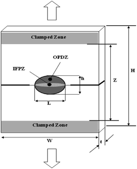 | ||
| Fig. 1 Double-edge-notched tensile (DENT) specimen used for EWF tests, showing the different energy dissipation zones involved. | ||
2.7 Fractography
To study the micro-mechanisms of deformation and fracture behaviour of the blends, the post-mortem SEM fractography was applied in two different planes of fractured EWF test samples. In the direct observation, the regions near the notch and at the center of fractured ligament were examined. Another plane was normal to the fractured ligament for analysis of sub-surface deformation mechanisms.3. Results and discussion
3.1 Morphological characterization
As stated in introduction, in our previous work the rheology and morphology of the PP/PA6/EPDM ternary blends and their reference binary systems were studied in detail. In this paper a summary of the morphology results is presented, because of the close relationship between the fracture behaviour and the morphology of the different samples.The SEM micrographs of the cryogenically fractured surfaces of different PP/PA6/EPDM blend systems without and with 5 wt% of PP-g-MA are shown in Fig. 2 and 3. As can be seen in the micrographs, the morphological texture of all the blends is typically of matrix/dispersed type.
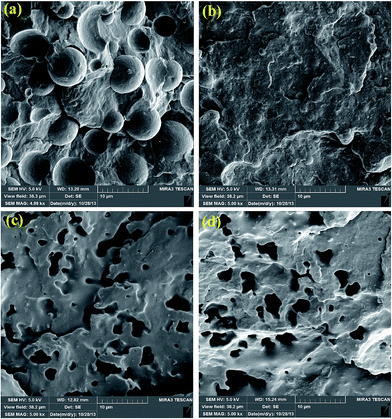 | ||
| Fig. 2 SEM micrographs of binary blends without (a and c) and with 5 wt% PP-g-MA (b and d). (a and b: PP/PA6) and (c and d: PP/EPDM). The EPDM phase was etched by cyclohexane. | ||
Similar to PP/PA6 binary blend, the incorporation of 5 wt% PP-g-MA into different PP/PA6/EPDM ternary blends caused a remarkable change in the phase structure of these blends. The size of dispersed PA6 domains was drastically reduced upon the introduction of PP-g-MA, so that the PA6 phase domains were almost completely wetted by the matrix phase. As a result, it becomes difficult to distinguish the PA6 dispersed particles from the matrix phase.
3.2 Crystalline structure of the samples
Since different mechanical properties, and specifically the fracture toughness of the blends studied in the present work, are strongly dependent on the crystalline structure of the blend components, it is important to study the effect of blending process, dispersed phase composition and compatibilization process on the crystalline structure of the matrix material (PP). The X-ray diffraction patterns in terms of intensity versus 2θ measured in the 2θ range of 10–50° for some of binary and ternary blends together with that of neat PP polymer are shown in Fig. 4.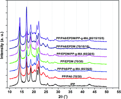 | ||
| Fig. 4 XRD patterns for the pure PP, PP/PA6, PP/EPDM binary blends and PP/PA6/EPDM 70/15/15 ternary blends. | ||
Five distinct peaks at 2θ of 13.9°, 16.7°, 18.3°, 21.0° and 21.7° corresponding to the (110), (040), (130), (131) and (041) planes are observed in XRD patterns of iPP and its blends. These peaks correspond to the monoclinic α-crystalline phase of PP from crystallography point of view. For binary and ternary blends containing PA6 as the dispersed phase(s), the peaks at 2θ of 20.2° and 23.7° are, respectively, assigned to (200), (202) and (002) planes of α-form crystals of PA6 dispersed component. The intensity of these peaks in ternary blends is lower than those in the binary blends, likely due to lower content of PA6 phase in the ternary blends than the PP/PA6 binary blends. It is important to note that there is no evidence of the formation of β-crystalline phase in the pure iPP and different binary/ternary blends studied in the present work. β-crystalline phase of iPP shows two strong peaks at 2θ of 16.2° and 21.2°.46–48 Therefore it is suggested that the probable differences in mechanical properties and/or fracture behaviour of the samples would be in the results of morphology rather than the crystalline structure.
3.3 Essential and non-essential works of fracture
To characterize the fracture toughness of ductile polymers, polymer blends and composites two approaches of elasto-plastic fracture mechanics (EPFM) and post-yield fracture mechanics (PYFM) seem to be the most straightforward: the J-integral approach and the essential work of fracture (EWF) method. Although the J-integral approach has been used traditionally for this purpose, the EWF method has gained popularity because of its experimental simplicity as the method avoids the measurement of the current crack advance as well as the detection of cracking initiation.49The development of the EWF approach is credited to Broberg.50 The pioneering role in the extension of the EWF to polymers should be assigned to Mai and coworkers.51,52 The EWF concept states that when a pre-cracked specimen fractures, the total energy required to fracture (Wf) can be divided into the essential work of fracture (We) and non-essential or plastic work of fracture (WP). We is the work spent for the crack advance and generation of a new surface in the inner fracture process zone (IFPZ) and WP is the work consumed in the outer plastic deformation zone (OPDZ). Fig. 1 shows schematic representation of the two zones in a double edge notched tension (DENT) specimen. In the IFPZ, the real fracture process takes place, and in the OPDZ, various types of plastic deformation such as crazing, shear yielding and micro-voiding may be operating. The relationship between work of fracture and its components can be written as follows:
| Wf = We + WP | (1) |
The term We is essentially a surface energy term whose value is proportional to the ligament area (Lt) and WP is a volume-related energy term value of which is proportional to the volume of the yielded zone. Thus:
| We = weLt | (2) |
| Wp = wpβL2t | (3) |
Inserting eqn (2) and (3) into (1) and rearranging gives;
 | (4) |
3.4 Load–displacement curves
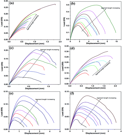
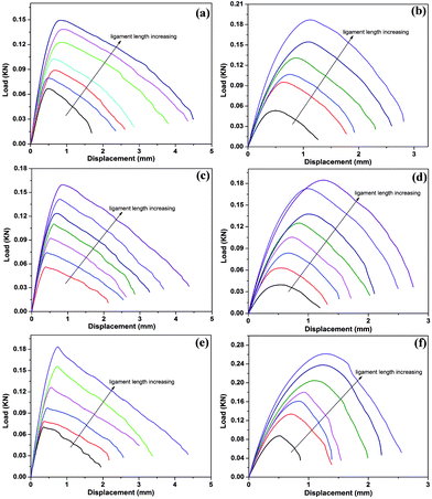
The load–displacement curves of DENT specimens for neat PP and PA6 components, binary and ternary blends as functions of ligament length, recorded under EWF test, are shown in Fig. 5 and 6. The shape of load–displacement curves varied depending on the material tested, implying the different fracture behaviour of the different samples during the EWF tests. From Fig. 5 it is visible that neat PP and PP/PA6 binary blend failed, respectively, in semi-brittle and semi-ductile manner, while the neat PA6 and PP/EPDM binary blends exhibited fully ductile mode of failure. Moreover, all the ternary systems fractured in fully-ductile manner with stable crack propagation (Fig. 6). In addition, compatibilization by PP-g-MA changed the fracture behaviour of ternary blends as evidenced by the shape of load–displacement curves.Generally, The total area under the curve, Wf, the maximum load, Fmax, and the extension at break, eb, all increased with increasing ligament length, L, for a given sample. Most importantly, for each sample (especially those with ductile tearing behaviour) the curves obtained are similar to one another for different ligament lengths, which is an essential prerequisite for validity of EWF testing. This “self-similarity” ensures that the cracks propagate under similar conditions, being unchanged with the ligament length.53,54 It should be noted that the PYFM theory invalidates the use of EWF approach for evaluation of fracture toughness of pure PP and PP/PA6 blends that display unstable crack propagation. Otherwise, the fracture energies obtained for these samples are apparent values not the intrinsic properties. Nevertheless, the crack resistance of these materials was determined by the procedure of EWF methodology to provide a qualitative comparison with those calculated for ductile samples. The full-ligament yielding before the onset of crack growth is another criterion for the application of EWF method.54 with the exception of pure PP and PP/PA6 binary blends as reference samples, for all other samples which showed ductile fracture behaviour the maximum load on the load–displacement curves was coincided with the full yielding of ligament region after which both edge pre-cracks simultaneously started to propagate through the yielded ligament.
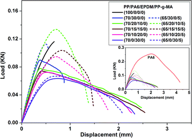
Investigation of deformation behaviour of different samples at a fixed ligament length could provide useful information about the crack resistance of materials as affected by dispersed phase(s) type, concentration and compatibilization process, as depicted in Fig. 7. According to Fig. 7, the uncompatibilized and compatibilized PP/PA6 binary blends showed much larger resistance against deformation, as reflected in the slope of initial part of diagrams, in comparison with neat PP, and the former has much lower maximum load value along with more stable crack propagation than the latter one. With the progressive replacement of PA6 phase by EPDM phase in the blends, the deformation resistance and maximum load gradually decreased whereas the displacement at maximum load and at break increased owing to the rubber toughening effect of EPDM component. The same trend was observed in deformation behaviour of compatibilized blends as a function of EPDM content. It was found that compatibilized blends represent higher deformation resistance, maximum load and displacement at which the maximum load has occurred in conjunction with a reduction in displacement at failure as compared with the uncompatibilized counterparts. It is also apparent that the slope of load–displacement curves during the tearing stage of fracture process is much steeper for compatibilized systems than the uncompatibilized ones, suggesting less stable crack propagation in the former blends. The degree of change in the above-mentioned deformation characteristics upon compatibilization is directly proportionate with the content of PA6 phase in the blend.
3.5 Variations of EWF parameters
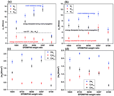
The plots of wf versus L for neat PP and PA6 components, binary and ternary blends are shown in Fig. 8. It is worthwhile noting that the wf–L diagrams gave very good linear relationship for all the materials studied, as proved by the linear regression coefficient (R2) which in most cases were higher than 0.97. The values of we and βwp obtained from the interception and the slope of the straight lines extrapolated to zero ligament length are plotted against EPDM/PA6 weight ratio in Fig. 9. The neat iPP, as a reference material, showed very low values of specific EWF and specific non-EWF parameters. There was no sign of plastic deformation neither on the fractured surface nor in the outer zone surrounding the fractured ligament during the crack propagation stage. A very small and poor damage zone was developed at the roots of edge notches at the final stage of the fracture test immediately before the maximum load is reached, suggesting that very small plastic work has been dissipated during the fracture process. This poor crack-tip plasticity, mostly in the form of crazing, was responsible for some nonlinearity occurred at deformations before ultimate failure of the specimen. Therefore, most of the energy consumed for fracture of iPP sample was associated with the crack initiation stage (4 N mm−1) rather than crack propagation stage (0.80 N mm−2). This is a characteristic of brittle-like behaviour with low fracture toughness by which the material catastrophically fails in a fast and unstable crack propagation manner. On the other hand, PA6 homopolymer showed the highest value of crack resistance parameters, i.e. we = 16 N mm−1 and βwp = 21 N mm−2, which seem reasonable again by examination of its fracture behavior in comparison with other samples, as depicted in the inset of Fig. 7.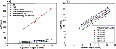 | ||
| Fig. 8 Specific total work of fracture wf against ligament length L for different samples. (a) neat components and binary blends, (b) uncompatibilized and compatibilized PP/PA6/EPDM ternary blends. | ||
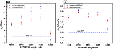 | ||
| Fig. 9 Specific work of fracture parameters for samples studied. (a) specific essential work of fracture, we and (b) specific plastic work of fracture, βwp. | ||
The introduction of PA6 into PP without compatibilization resulted in a decrease in the fracture toughness and a slight increase in the plastic work. The reduced fracture energy comes from the presence of weak micro-structural paths at the interface between the components which facilitate crack initiation in the blend. Consequently, the work consumed for crack advance through the material is reduced. Compatibilization increased the PP/PA6 blend's resistance to both crack initiation and propagation to values even higher than those for pure PP. For PP/EPDM binary blends, the specific EWF and specific plastic work values are larger than those obtained for compatibilized PP/PA6 blend, as expected. Obviously, this originates from rubber toughening effect of dispersed EPDM particles in the blend which will be discussed in the following sections. It is interesting to observe that PP-g-MA copolymer has no significant effect on the work of fracture parameters of PP/EPDM binary blend. This finding is in good consistency with the results of morphological studies conducted on PP/EPDM binary blends described earlier.
In the case of ternary blends, the data presented in Fig. 9 are noticeable from the following aspects:
The first aspect is that while the addition of PA6 into iPP reduced the fracture toughness of the material, it is interesting to observe that its progressive incorporation into PP/EPDM blend (to achieve a ternary blend) gradually increased the specific EWF values. The data further demonstrate higher fracture toughness values for uncompatibilized ternary blends than their compatibilized counterparts. This finding is very interesting because the dispersed PA6 domains are highly stiff with yield stress values much higher than the tensile strength of the PP matrix. Moreover and most importantly, in uncompatibilized ternary systems which showed higher fracture toughness values, the dispersed PA6 domains are very big in size and poorly bonded to the matrix at the interface region. All of these factors contradict the fundamental prerequisites for efficient energy dissipation according to the toughening concepts.
The second point is that the ternary blends have larger specific non-EWF values than that of the PP/EPDM binary blends, in addition to the specific EWF values. As reported in the literature, the improved fracture toughness observed for different systems assessed by EWF approach has usually been accompanied by a loss in the resistance to crack propagation (βwp) parameter.46,55–57 It is obvious that the increase in fracture resistance through a simultaneous improve in both the resistance to crack initiation and crack propagation stages of the fracture process would be much more desirable. In the present work both parameters (we and βwp) improved simultaneously with the addition of PA6 phase into rubber toughened binary PP/EPDM blend.
The third point is that compatibilization lowered the specific EWF and specific non-EWF values of the ternary blends. The interesting finding is that providing strong interfacial adhesion, between the PA6 dispersed domains and the PP matrix, via compatibilization using PP-g-MA, has a negative impact on fracture toughness of PP/PA6/EPDM ternary systems while a positive effect on the fracture resistance of PP/PA6 binary blend was observed. It is important to remember and note that in ternary blends, compatibilization preferentially affects the interfacial properties between PA6 component and PP matrix, not the PP/EPDM interface, exactly the same effect as that takes place in the PP/PA6 binary blend.
Finally, owing high rigidity and stiffness of PA6, an increase in the blend's stiffness and strength is also expected with the incorporation of PA6 phase into toughened blend, which will be verified in the following sections. With this respect, the results of mechanical and fracture toughness analyses would be promising in designing materials with balanced stiffness, strength and toughness for engineering applications.
The reason behind the higher fracture toughness achieved by the introduction of stiff PA6 domains into PP/EPDM binary system, which may be so called as “rigid toughening effect”, will comprehensively be discussed in the following sections. In fact, a synergistic toughening effect from the simultaneous presence of soft EPDM particles and stiff PA6 domains on the fracture resistance of the ternary system was observed.
3.6 Constituting terms of essential and non-essential work of fracture
As discussed in the literature,54 the total work of fracture can be partitioned at the maximum load as the sum of two contributions: a term Wy related to the yielding of the ligament area and another term Wt associated with the subsequent tearing. Therefore it can be written:| Wf = Wy + Wt | (5) |
The specific terms (wy and wt) can be expressed as functions of ligament length similar to eqn (4), as follows:
| wf = wy + wt = (we,y + βywp,yl) + (we,t + βtwp,tl) | (6) |
| we = we,y + we,t | (7) |
| βwp = βywp,y + βtwp,t | (8) |
The results for splitting the essential and non-essential works of fracture as yielding and tearing terms are given in Fig. 10, which were obtained by plotting wy and wt versus L. The regression coefficients (R2) obtained for all the samples were above 0.97, which indicates that the partitioning method is also well applicable for these systems.
For neat PP which failed at the maximum load in semi-brittle mode, the we value is almost entirely contributed by the yielding component (we,y) with approximately no contribution from tearing component (we,t ≈ 0). The same explanation could be applied for βwp components of pure PP. The little dissipated work is entirely consumed during the yielding stage of ligament (βywp,y = βwp) by the formation of crack-tip crazing with no participation from tearing stage (βtwp,t = 0). For PA6 polymer with fully ductile fracture behaviour, the contributions made to we and βwp by different components are comparable in values. The results show that the contribution on we from yielding component is higher than the tearing component for PA6. This could be attributed to the very high value of PA6 yield stress which consumes greater energy for activation of shear yielding at the crack tip region. These results are reflections of the results obtained from comparing the area under the load–displacement curves before and after the maximum load for different samples at a fixed ligament length (Fig. 7). Indeed, the curves in Fig. 7 provide very useful information for evaluation of the effect of dispersed phase type, concentration and compatibilization on the energies consumed at the yielding and subsequent tearing stages of the fracture process. It is worth noting that since the onset of crack initiation is immediately after the full yielding of ligament region, the we,y values may be regarded as the specific EWF for crack initiation. Subsequently, the term we,t can be regarded as specific EWF for crack propagation and tearing. Accordingly, for PP the fracture energy is entirely consumed for crack initiation, after which the cracks grow spontaneously with a very fast velocity. This is characteristic of catastrophic brittle fracture with completely unstable crack propagation. In PA6, a high degree of crack tip blunting as a consequence of extensive crack tip plasticity, significantly lowers the triaxiality of stress state at the crack tip which, in turn, increase the energy for crack initiation (we,y) rather than crack propagation (we,t). This could also be readily deduced from the load–displacement curve of PA6 in the inset of Fig. 7. The contributions of yielding and subsequent tearing components on βwp are the same for PA6.
For uncompatibilized PP/PA6 blend with some instability during the crack growth, the energy dissipated during the tearing stage is much larger than that consumed for yielding of the ligament region. This is likely due to the presence of weak micro-structural regions in the blend which are susceptible for early crack initiation at low levels of applied stresses. In fact, most of plastic work is dissipated during the yielding of ligament (βywp,y) and little energy is dissipated during the tearing of the ligament (βtwp,t). Compatibilization of PP/PA6 blend substantially increased the yielding component of we along with a loss in the tearing component. In other words, the compatibilized PP/PA6 blend has a greatly improved resistance to onset of crack growth (we,y) together with a lower resistance to the crack propagation (we,t) than the uncompatibilized one. It can be concluded that the improved contribution from we,y component is responsible for larger crack resistance (we) of compatibilized PP/PA6 blend.
In the case of PP/EPDM binary blends it is clearly apparent that the contributions made to we and βwp by tearing components are larger than those made by yielding components. This indicates that the amount of energy required for yielding of the ligament (material) up to crack initiation stage is lower than the energy consumed for crack growth and ductile tearing of the material. The comparison between PP/EPDM and PP/PA6 blends suggested that higher fracture toughness of PP/EPDM blend than that of PP/PA6 blends is attributed to the remarkably increased resistance of rubber toughened blend against crack propagation process. Obviously, the increase in material resistance against crack propagation is interrelated with the yielding capability of the material which determines the volume of material in front of crack tip participating in the energy absorption processes.
The data also demonstrate that with progressive replacement of soft EPDM phase by stiff PA6 in the PP/EPDM blend, to form ternary systems without PP-g-MA, the contribution from yielding component (we,y) gradually decreases whereas the contribution made by tearing (we,t) steadily increases. This suggests that the amount of energy needed for yielding and crack initiation reduces monotonically whilst the energy required for subsequent crack propagation and ductile tearing gradually increases. Since the crack resistance increased with PA6 content in uncompatibilized ternary blends, it can be concluded that the improve in we with increasing PA6 weight fraction is controlled by its tearing component, i.e., we,t.
For all the ternary blends, compatibilization process increased the contribution from yielding component in conjunction with a reduction of contribution from tearing component. It is believed that the remarked increase in the yield stress of ternary blends upon compatibilization is responsible for higher energy required for yielding and crack initiation (increase in we,y) which consequently resulted in a decrease in the plastic drawing and post yield deformation (decrease of we,t) of the blends. The extent of these changes in compatibilized ternary blends is directly related to the concentration of PA6 in the system. This is why the we,y component gradually increased while the we,t component tends to decrease with the weight fraction of PA6 in the compatibilized ternary blends. Since compatibilized ternary blends have lower fracture toughness (we) values than the uncompatibilized blends, it can be inferred that the reduction of we upon compatibilization is dominated by its tearing component, i.e., we,t. It is worth noting that in compatibilized ternary blends the gradual increase in the concentration of PA6 phase resulted in a monotonic increase in the yielding-related specific EWF and a gradual decrease in the subsequent tearing-related component, in contrast with the uncompatibilized ternary blends. In the case of βwp parameter of ternary blends (Fig. 10c and d), the contribution from tearing (βtwp,t) is larger than that made by yielding (βywp,y) and compatibilization has the same effect as that observed on the yielding and tearing components of we parameter.
3.7 Validity of EWF measurements
It is worth noting that since the smallest ligament length used in this study was ten times of specimen thickness, 10t (meeting the lower limit for L according to ESIS protocol), and the observation of self-similarity as well as linear dependence of wf versus L over the entire range of ligament length under consideration, it is reasonable to assume that the state of stress in the ligament region is that of pure plane-stress state. To further ensure that the EWF data have been conducted under plane-stress conditions, net-section stress at maximum load, σn, was calculated at each ligament length for the samples which satisfied the main prerequisites of EWF theory (samples with ductile tearing in this work). Then, the results were checked with Hill's stress level and stress criterion, as proposed by the ESIS protocol.54,58 The results (not shown here for the sake of brevity) showed that all the experiments have been conducted under plane-stress condition, indicating the validity of data obtained and test results.3.8 Fracture behaviour and toughening mechanisms
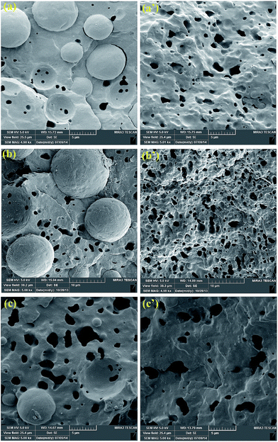
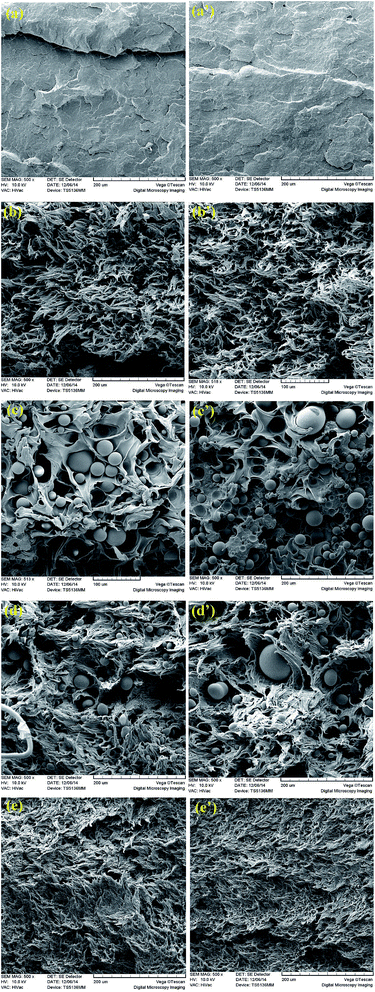
The failure mode and toughening mechanisms involved in the fracture process of some of blend systems along with that for iPP reference sample are shown in Fig. 11. The micrographs are obtained from direct observation of different areas on the IFPZ (regions of crack initiation and final stage of crack propagation). For neat iPP a smooth and featureless surface was observed over the whole of fractured ligament (Fig. 11a and a′). This is characteristic of brittle failure, with no sign of effective energy dissipation process. This is consistent with the relatively low we and βwp values of iPP. Compared to featureless fracture surface of iPP, the SEM micrographs of PP/EPDM binary blend (Fig. 11b and b′) showed much greater plastic deformation and cavitation. The fracture surface in this case is no longer smooth. Tiny and elongated voids formed via debonding and/or internal cavitation of EPDM rubber particles along with a typical fibrillated structure caused by extensive plastic stretching and tearing can clearly be observed. This extensive plastic deformation is responsible for the toughness enhancement shown in Fig. 9a and b. During the uniaxial loading, the stress concentrating rubber particles in PP/EPDM binary blends debond from the surrounding matrix material and/or undergo internal cavitation in a response to stress fields. In addition, multiple crazing is another important deformation micro-mechanism by which a significant amount of applied energy for fracture of the toughened blend could be dissipated. It is well established that rubber particles act as craze initiators and craze terminators (stopper).59,60 The activation of these dilatational micro-mechanisms (interfacial voiding, internal cavitation and multiple crazing) at the plastic zones developed ahead of pre-cracks during the fracture test relieves the detrimental triaxial stress fields to biaxial and uniaxial stress state. The latter stress states are favourable to shear yielding and plastic deformation of matrix material in-between and/or around the dispersed EPDM particles. As a result, the resistance of material to crack initiation and subsequent crack propagation was increased as the large volume of material in front of crack tip participates in energy absorption/dissipation processes. The micro-mechanical deformations induced by EPDM rubber particles in the PP/EPDM binary blends elucidated above, are also expected to be operative in the ternary blends investigated in the present work, the extent of which would depends on the weight fraction of rubbery component in the ternary system.For uncompatibilized PP/PA6 binary blend (Fig. 11c and c′), it is interesting to observe that the presence of very rigid and stiff PA6 phase in iPP caused some limited and localized plasticity in the matrix. The observation of relatively smooth fracture surface at the final stage of crack propagation region indicates to unstable crack growth in this sample (Fig. 11c′). The poor shear yielding in the blend is believed to be triggered mainly by stress-relieving particle debonding and interfacial void formation mechanism as a result of stress concentrating effect around the PA6 dispersed nodules. It is reported that this debonding–cavitation mechanism in rigid phase filled systems has the same effect as the cavitation inside the rubber particles in rubber toughened blends. Although the fracture energy (we) of the uncompatibilized PP/PA6 blend is lower than that of iPP, this weak plastic deformation is responsible for its higher βwp value than the iPP. For uncompatibilized PP/PA6/EPDM (70/20/10) ternary blend with the highest fracture toughness value, the SEM micrographs in Fig. 11d and d′ reveal the massive shear yielding and plastic flow of the blend.
The debonded PA6 phase domains which are surrounded by cavitated and highly deformed matrix material are clearly visible in the micrographs. It is suggested that large and stabilized debonding–cavitations around the rigid PA6 domains together with various dilatational processes related to the dispersed EPDM particles are responsible for significant plastic deformation of low rubber content uncompatibilized PP/PA6/EPDM ternary blend.
According to SEM observations, it can be concluded that the substantial increase in toughness of uncompatibilized ternary blend has contributions from several toughening mechanisms. Among these are various dilatational mechanisms respective of PA6 and EPDM minor components, strong shear deformation of the matrix and crack bridging caused by extensive stretching.
Although the SEM images in Fig. 11e and e′ represent the ductile tearing of the compatibilized PP/PA6/EPDM (70/20/10) sample, it seems that the intensity and texture of the fracture surface are different from those for its uncompatibilized counterpart. Here the toughening mechanisms are mostly related to the dispersed rubber particles with no positive contribution from finely dispersed PA6 nodules. Moreover, the effect of crack bridging mechanism seems to be less significant in the compatibilized blend than its uncompatibilized counterpart as the extent of plastic stretching is less intense for the former blend than the latter one. As a result, the crack tip could not be blunted as effective as that for uncompatibilized ternary blend with more intense plastic deformation. Therefore, the fracture energy would reduce as the crack propagation becomes easier in the compatibilized blend.
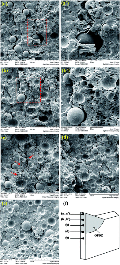
According to the EWF theory, during the ductile tearing the fracture process zone is usually surrounded by a plastic zone visible as a stress-whitened region. This macroscopic stress whitening illustrates the different microscopic deformation processes operative in the material. Therefore, the study on the microstructure of material at different distances from the fracture surface within the plastically deformed region would be beneficial to get more insight into identifying the different energy-absorbing micromechanical deformations accompanying the fracture process. Fig. 12 shows the sub-surface SEM micrographs obtained from core region of uncompatibilized PP/PA6/EPDM (70/20/10) ternary blend with the highest fracture toughness at different distances from crack plane, at the middle of ligament. For this sample the OPDZ was composed of an intense outer plastic zone and a diffuse outer plastic zone (IOPZ and DOPC, respectively). According to Fig. 12e, far from the fracture plane (zone (e) in Fig. 12f) no damage and no sign of matrix deformation are visible. Closer to the ligament (Fig. 12d), inside the DOPZ, the interfacially debonded PA6 domains and some cavitated rubber particles (tiny dark spots) are found. Much closer to fracture plane within the IOPZ (Fig. 12a–c) extensive rubber particles cavitation, void formation around the dispersed PA6 domains and large plastic deformation of the matrix are clearly visible. The highly elongated rubber particles and plastically drawn interfacial voids surrounding PA6 particles are also apparent at IOPZ (Fig. 12a′ and b′). The direction of elongation of voids is in the tensile direction. These elongated voids are formed as a result of strong plastic deformation of surrounding matrix. The various cavitational processes increase in frequency and size as the fracture surface is approached which, in turn, led to progressive increase in the intensity of plastic flow of the surrounding matrix material at nearer positions of the fracture surface. In addition, the development and interaction of different voids in the matrix led to the formation of deformation bands with the orientation perpendicular to the tensile loading. Close examination of micrographs (Fig. 12a′, b′ and c) reveals that the deformation bands have a void-fibrillar microstructure which makes them similar to the so called dilatational bands/craze-like features observed in other toughened blends. Both narrow and thick dilatational bands are visible in the micrographs. The narrow bands are mainly consisted of the cavitated small rubber particles while the thicker bands are composed of small rubber particles-related cavities and much larger PA6-induced interfacial voids. This indicates that dispersed PA6 particles also contribute at micro-crack/craze initiation and/or termination, similar to soft EPDM rubber particles. It is reported that the nucleation and propagation of these deformation bands is a viscoelastic process which dissipates a tremendous amount of fracture energy. Moreover, the generation of above-mentioned deformation zones, activate the shear yielding of the matrix which further improves the energy absorption capability of the blend. According to the SEM images presented in Fig. 12, it is suggested that the formation of large interfacial voids at the interface between PA6 particles and matrix and their plastic growth under tensile loading, remove the plastic constraint and, therefore, facilitate the yielding and plastic flow of the matrix material. In other words, in the same manner with the soft EPDM particles, the big and stiff PA6 phase domains also activate different micromechanical deformations in the blend which at the presence of the rubber particles, synergistically improve the fracture toughness of the uncompatibilized PP/PA6/EPDM (70/20/10) ternary blend.
3.9 Discussion on rigid toughening effect induced by dispersed PA6 phase domains
As observed above, in this study the progressive replacement of EPDM rubbery phase by rigid PA6 in the PP/EPDM blend gradually increased the fracture toughness of material as long as the rubbery phase is still present in the blend. However, when the total dispersed phase was consisted of PA6 phase domains, a sharp reduction in the fracture energy was observed even to value lower than that of neat PP. The improvement in fracture toughness of semicrystalline polymers, such as iPP, by the incorporation of a rigid phase has been reported by researchers in the literature.12,13,17–20,61 Wei et al.61 reported that the fracture toughness of iPP can significantly be improved by adding rigid Noryl polymer along with the alteration of fracture behaviour from brittle to ductile, which was thought to be due to the stress concentrating and craze stabilizing effects of Noryl particles, resulting to the multiple crazing in iPP/Noryl blend. Compatibilization using styrene–ethylene–propylene (SEP) further increased the energies required for both crack initiation and crack propagation which in turn led to the change in deformation mechanism from crazing into crazing/shear yielding. Yang et al.12,13 reported a dramatic increase in the Izod impact strength of PP/EPDM blends by incorporation of rigid SiO2 nanoparticles. They ascribed this improved toughness to the overlap of stress volume between EPDM and SiO2 particles, resulting from the formation of a unique structure with the majority of EPDM particles surrounded by hydrophilic SiO2 nanoparticles (network-like structure). Generally, the improved fracture toughness of semicrystalline matrices upon the introduction of rigid polymers or inorganic fillers has been attributed to the debonding of rigid phase from the surrounding matrix material as a consequence of stress concentrating effects. It is well established that the rigid dispersed particles can serve as stress concentrators to trigger cavitational mechanisms, such as crazing and interfacial debonding, and relieve the crack tip triaxial stress constraint, which then leads to massive shear banding in the matrix. This is much like the cavitation mechanism in rubber toughened systems.17–20 However, it should be noted that for the rigid filler particles to act as toughener, they must be small size otherwise the interfacial voids and micro-cracks that are nucleated would act as initiation sites for fracture process. In fact, the creation of stable free volume and/or interfacial voids is what is desired.18 In the case of uncompatibilized ternary blends studied in this work, both small EPDM rubber particles and large PA6 phase domains act as stress concentrators. By considering the fact that the pure PA6 has the significantly larger we and βwp values than the neat iPP and PP/EPDM binary blends, the gradual increase in the fracture toughness of uncompatibilized and compatibilized ternary blends with PA6 content could not be attributed to the deformation of PA6 component. In the uncompatibilized ternary blends this is due to poor interfacial bonding between the minor PA6 phase and the matrix, while for compatibilized systems this could be ascribed to the presence of finely dispersed PA6 domains with plastic-flow stress value much larger than the ultimate strength of the matrix. Therefore, no deformation is expected for dispersed PA6 phase domains in the ternary blends under the fracture tests. In the uncompatibilized ternary blends, the dispersed soft EPDM particles could debond from the matrix, may undergo internal cavitation or even could induce multiple crazing mechanisms in the matrix, as stated before. On the other hand, the stiff PA6 dispersed domains which are closely surrounded by the EPDM rubber particles in the matrix, is expected to debond from the matrix followed by the development of interfacial void formation and/or micro-cracking/crazing in the surrounding matrix in response to stress concentration effects. Independent of polar phase concentration in the blend, the micro-cracks and voids formed at the interface region between the large PA6 domains and the matrix would be large enough (critical size) to serve as fracture initiation sites in the material. In the absence of a controlling and stabilizing mechanism for these critical-size defects the material will fail in unstable manner with low fracture energy as that observed in uncompatibilized PP/PA6 blend. It should be noted that since the PA6 dispersed domains are much larger in size with much lower interfacial strength with the surrounding matrix as compared with those for EPDM and PP matrix, the presence of large PA6 dispersed domains in uncompatibilized ternary blends facilitates the activation of PA6-induced different cavitational micromechanisms in the surrounding matrix. Provided that these stress relieving mechanisms, which are randomly distributed throughout the material, are stabilized and being prevented from rapid propagation, a high degree of applied energy could be absorbed and/or dissipated in the same manner with those observed in systems toughened with inorganic fillers. This is further confirmed by results of experimental data for yielding and subsequent tearing-related contributions of we parameter as a function of PA6 content in the uncompatibilized ternary blends. The earlier activation of multiple deformation mechanisms by dispersed PA6 domains is reflected in a gradual decrease in the energy required for the onset of crack growth (we,y) with PA6 content whereas an improved energy dissipation capacity of the blends with PA6 content is manifested by a monotonic increase in the energy needed for crack propagation and tearing (we,t). It is believed that deformation zones activated around the large PA6 domains in uncompatibilized ternary blends are controlled by a large number of small rubber particles present in the matrix around/next to the PA6 droplets. In other words, the shear yielding and plastic deformation of rubber toughened matrix around the critical size deformation zones have a stabilizing effect for voids and/or micro-cracks nucleated at the weak interfacial regions between PA6 and matrix (Fig. 13a). By considering that the different cavitational micro-deformations around the PA6 dispersed droplets further relieve the triaxial concentrated stress fields into plane stress state on the surrounding matrix material, these stabilized mechanisms would additionally enhance the energy dissipation capability of the blend through encouraging the shear deformation of matrix. Therefore, increasing PA6 content in uncompatibilized ternary blend not only has no detrimental effect on the fracture resistance of the material but also participates larger volume of blend into deformation process by early activation of multiple deformation mechanisms in the blend as long as the rubber particles are present in the matrix to prevent premature failure of the material.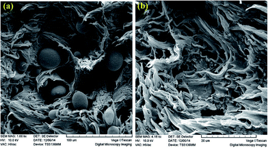 | ||
| Fig. 13 SEM images of fracture surfaces at the notch regions of EWF-test specimens. (a) Uncompatibilized PP/PA6/EPDM 70/20/10 ternary blend and (b) compatibilized PP/PA6/EPDM 70/20/10 ternary blend. | ||
Upon compatibilization, the PA6 particles become finely dispersed in the matrix phase with strong intermolecular interactions at the interfacial region between the PA6 and matrix. As a consequence, the highly adhered PA6 domains could not debond and/or detach from the surrounding matrix (Fig. 13b). Therefore, the concentrated stress field around dispersed PA6 domains could not relieve via different cavitational mechanisms described earlier. Moreover, the yield stress of the blend also will significantly increase with compatibilization (see following section). The latter case would additionally reduce the shear yielding capability of the compatibilized material. As a result, the compatibilized ternary blends represent lower fracture toughness values than their uncompatibilized blends. The increase in fracture resistance (we) of compatibilized ternary blends with PA6 content could be attributed to gradual improvement in load-bearing capability of the toughened-blend. It is worth noting that exhibiting a high degree of tensile ductility is not enough for achieving a high fracture resistance value, but the material should have some load-bearing capacity during the deformation process. In the presence of rubber particles which induce ductility in the blends, the progressive introduction of stiff PA6 phase into compatibilized blend steadily enhance the stiffness and ultimate strength.
3.10 Mechanical properties under tension
The stress–strain behaviours of various binary and ternary blends together with those for neat PP and PA6 polymers under uniaxial tensile tests are given in Fig. 14. The neat PP failed in semi-ductile manner (Fig. 14a) while pure PA6 exhibited a ductile behaviour with larger elongation at break and much higher stiffness and strength as compared with pure PP. The incorporation of 30 wt% of PA6 homopolymer into PP changed the mechanical response of the material from semi-ductile to semi-brittle type. Compatibilization altered the tensile response of PP/PA6 blend to semi-ductile type again.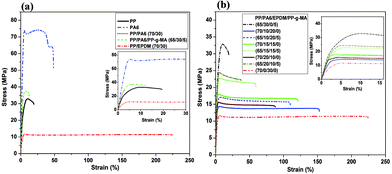 | ||
| Fig. 14 Typical stress–strain curves for (a) neat PP, PA6 polymers and different binary blends, and (b) PP/PA6/EPDM ternary blends of different dispersed phase's compositions. | ||
The introduction of 30 wt% EPDM into PP transferred the macroscopic tensile behaviour of parent material from semi-ductile to fully ductile. However, this improved tensile ductility was obtained at the cost of a significant loss in material's stiffness and strength (Fig. 14a). As can be seen in Fig. 14b, all the uncompatibilized and compatibilized ternary blends broke in a ductile manner. However, the extent of post-yield deformation stability in the ternary systems depends on the PA6/EPDM weight ratio in the blend as well as the compatibilization process.
The tensile parameters obtained from stress–strain curves for different PP/PA6/EPDM blend systems are displayed in Fig. 15. The Young's modulus, yield stress and tensile strength values of the blends gradually increased whereas the strain at break monotonically decreased with the progressive replacement of EPDM phase by PA6 component for both uncompatibilized and compatibilized systems.
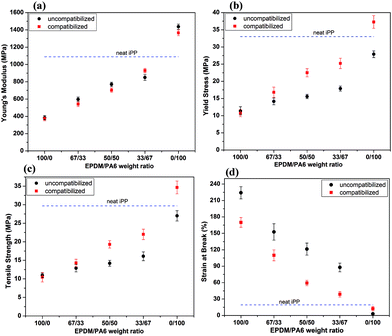 | ||
| Fig. 15 Tensile properties of the PP/PA6/EPDM blend systems as a function of EPDM/PA6 weight ratio. (a) Young's modulus, (b) yield stress, (c) tensile strength, and (d) strain at break. | ||
According to Fig. 15a, the effect of compatibilization on the blends' stiffness is not clear, probably due to the fact that the Young's modulus is a low-strain property. Obviously, the interfacial region between the components may not be affected at such small deformations. Compatibilization process has a more pronounced effect on the yield stress, tensile strength and strain at break values of the blends, contrary to the Young's modulus. This is because these parameters are directly related to the level of interfacial adhesion between the dispersed components and the matrix and, therefore, the load-bearing capacity of the multiphase system.
From Fig. 15b, it is apparent that the uncompatibilized PP/PA6 blend has lower yield stress than the PP matrix whereas the compatibilized one shows higher yield stress. According to SEM micrographs in Fig. 2, the former could be related to early debonding of PA6 dispersed nodules from the matrix as a result of poor interfacial bonding, while the latter can be related to the efficient stress transfer to the rigid PA6 domains owing to strong interfacial adhesion between the components. In the case of ternary blends, compatibilization increased the yield stress of the blends, the amount of which is in direct proportion with the PA6 content in the blends (Fig. 15b). This is because in PP/PA6/EPDM blends the PP-g-MA copolymer preferentially modifies the interfacial characteristics between the PA6 component and PP matrix.
The effect of compatibilization on the tensile strength is the same as that observed for yield stress (Fig. 15c). The ultimate strength of a multiphase system depends on the weakest fracture path throughout the material. Compatibilization enhances the load-bearing capability of the binary and ternary blends containing PA6 phase. In the same fashion with the yield stress, the extent of improvement in tensile strength upon compatibilization depends on the concentration of polar component in the blend. In the compatibilized blends, the strong phase adhesion between the minor components (mainly PA6) with the matrix prevents the formation of critical size defects in the microstructure by particle debonding. Therefore, the material could sustain higher loads.
With the strain at break, it is interesting in Fig. 15d to observe that compatibilization decreases the tensile ductility of the blends studied, except for compatibilized PP/PA6 binary blend. In PP/PA6 blend, it is believed that compatibilization increases the material's resistance against premature crack propagation. The detrimental effect of graft copolymer on strain at break of PP/EPDM binary blend comes from the very low molecular weight of PP-g-MA present in the blend. For ternary blends, the reduced elongation at break as a result of compatibilization originates from increased yield stress of the blend due to reinforcing effect of dispersed rigid PA6 particles. Consequently, compatibilized ternary blends showed a lower tendency to plastic drawing under applied tensile stress. It is important to note that the impact of compatibilization on the tensile ductility of the blend systems presented above is exactly the same as that observed on the specific EWF and specific plastic work parameters described earlier. By considering the results of tensile tests given in Fig. 15 together with those of fracture toughness analysis discussed previously, it can be concluded that the PA6 phase domains function as both the reinforcing agent and toughener in PP/PA6/EPDM ternary blends, which led to a simultaneous improvement in stiffness and quasi-static fracture toughness of the resulting blend.
4. Conclusions
Interestingly, greatly improved fracture toughness was obtained in uncompatibilized PP/EPDM/PA6 ternary blends with phase-separated morphology at lower rubber contents, as compared with PP/EPDM blend. Detailed quantitative analysis of fracture energy by EWF approach indicated that the dispersed PA6 phase domains facilitate the shear yielding and plastic deformation of surrounding matrix. This resulted in the gradual increase in energy dissipated during ductile tearing with PA6 content in uncompatibilized ternary blends. The fractographic analysis from surface and sub-surface of deformed samples revealed that poorly bonded PA6 phase domains also effectively contribute in stress relieving and energy-absorbing cavitational processes such as debonding, interfacial voiding, development of micro-craks/craze like dilatational bands and yielding of surrounding matrix. It is believed that the cooperative participation of both small soft EPDM particles and large stiff PA6 nodules in activation of different micromechanical deformation processes in the matrix is responsible for synergistic toughening effect of dispersed components in uncompatibilized ternary blends. Moreover, the rubber particles by activating the matrix shear yielding play a decisive role in controlling and stabilizing of the critical size deformation zones around the large polar PA6 phase domains. Compatibilized ternary blends exhibited lower fracture toughness values than the uncompatibilized counterparts, most probably due to the higher yield stress of compatibilized blends and inability of strongly-adhered small PA6 particles in nucleation and development of different energy dissipating mechanisms. According to the tensile tests, the Young's modulus, yield stress and tensile strength also increased with the PA6 fraction in the ternary blends. The results obtained from fracture analysis in conjunction with the tensile tests results showed that a simultaneous toughening and stiffening could be achieved via incorporation of PA6 into PP/EPDM blends.References
- D. R. Paul, J. W. Barlow and H. Keskkula, in Encyclopedia of polymer science and engineering, ed. H. F. Mark, N. M. Bikales, C. C. Overberger and G. Menges, New York, Wiley-Interscience, 1988, vol. 12, p. 399 Search PubMed.
- R. Dou, C. Shen, B. Yin, M. Yang and B. Xie, RSC Adv., 2015, 5, 14592 RSC.
- D. R. Paul, L. L. Cui, C. Troeltzsch and P. J. Yoon, Macromolecules, 2009, 42, 2599–2608 CrossRef.
- D. R. Paul, T. D. Fornes and D. L. Hunter, Macromolecules, 2004, 37, 1793–1798 CrossRef.
- M. H. Al-Saleh and U. Sundararaj, Polymer, 2010, 51, 2740–2747 CrossRef CAS PubMed.
- B. J. Busche, A. E. Tonelli and C. Maurice Balik, Polymer, 2010, 51, 1465–1471 CrossRef CAS PubMed.
- S. W. Deng, X. Z. Zhao, Y. M. Huang, X. Han, H. L. Liu and Y. Hu, Polymer, 2011, 52, 5681–5694 CrossRef CAS PubMed.
- V. A. Matonis and N. C. Small, Polym. Eng. Sci., 1969, 9, 99 Search PubMed.
- C. G. Sanporean, Z. Vuluga, C. Radovici, D. M. Panaitescu, M. Lorga, J. Christiansen and A. Mosca, RSC Adv., 2014, 4, 6573 RSC.
- K. Prephet and P. Horanont, Polymer, 2000, 41, 9283 CrossRef.
- J. Jancar and A. T. Dibenedetto, J. Mater. Sci., 1994, 29, 4651 CrossRef CAS.
- H. Yang, Q. Zhang, M. Guo, C. Wang, R. N. Du and Q. Fu, Polymer, 2006, 47, 2106 CrossRef CAS PubMed.
- H. Yang, X. Zhang, C. Qu, B. Li, L. Zhang, Q. Zhang and Q. Fu, Polymer, 2007, 48, 860–869 CrossRef CAS PubMed.
- L. Liu, Y. Wang, Y. Li, J. Wu, Z. Zhou and C. Jiang, Polymer, 2009, 50, 3072–3078 CrossRef CAS PubMed.
- S. Hikasa, K. Nagata, K. Miyahara, T. Izumi, T. Suda, A. Toyohara, A. Kato and Y. Nakamura, J. Appl. Polym. Sci., 2009, 114, 919–927 CrossRef CAS PubMed.
- H. Xiu, C. Huang, H. Bai, J. Jiang, F. Chen, H. Deng, K. Wang, Q. Zhang and Q. Fu, Polymer, 2014, 55, 1593–1600 CrossRef CAS PubMed.
- C. M. Chan, J. S. Wu, J. X. Li and Y. K. Cheung, Polymer, 2002, 43, 2981–2992 CrossRef CAS.
- W. C. J. Zuiderduin, C. Westzaan, J. Huetink and R. J. Gaymans, Polymer, 2003, 44, 261–275 CrossRef CAS.
- Y. Lin, H. Chen, C. M. Chan and J. Wu, Polymer, 2010, 51, 3277–3284 CrossRef CAS PubMed.
- Y. Liang, S. Wen, Y. Ren and L. Liu, RSC Adv., 2015, 5, 31547–31553 RSC.
- M. Umeda and I. Uchida, Langmuir, 2006, 22, 4476–4479 CrossRef CAS PubMed.
- J. S. Wu, P. Xue and Y. W. Mai, Polym. Eng. Sci., 2000, 40, 786–797 CAS.
- A. R. Bhattacharyya, A. K. Ghosh and A. Misra, Polymer, 2005, 46, 1661–1674 CrossRef CAS PubMed.
- L. P. Li, B. Yin, Y. Zhou, L. Gong, M. B. Yang and B. H. Xie, et al., Polymer, 2012, 53, 3043–3051 CrossRef CAS PubMed.
- T. S. Valera, A. T. Morita and N. R. Demarquette, Macromolecules, 2006, 39, 2663–2675 CrossRef CAS.
- P. L. Corroller and B. D. Favis, Polymer, 2011, 52, 3827–3834 CrossRef PubMed.
- S. Ravati and B. D. Favis, Polymer, 2010, 51, 4547–4561 CrossRef CAS PubMed.
- D. Shi, Z. Ke, J. Yin, R. K. Y. Li and Y. W. Mai, Macromolecules, 2008, 41, 7264–7267 CrossRef.
- D. Wang, Y. Li, X. M. Xie and B. H. Guo, Polymer, 2011, 52, 191–200 CrossRef CAS PubMed.
- S. Y. Hobbs, M. E. J. Dekkers and V. H. Watkins, Polymer, 1988, 29, 1598 CrossRef CAS.
- R. J. M. Borggreve and R. J. Gaymans, Polymer, 1989, 30, 63–70 CrossRef CAS.
- A. Oshinski, H. Keskkula and D. R. Paul, Polymer, 1992, 33, 268–283 CrossRef CAS.
- A. Gonzales-Montiel, H. Keskkula and D. R. Paul, Polymer, 1995, 36, 4587–4603 CrossRef.
- A. Gonzales-Montiel, H. Keskkula and D. R. Paul, Polymer, 1995, 36, 4605–4620 CrossRef.
- S. C. Wong and Y. W. Mai, Polymer, 1999, 40, 1553–1566 CrossRef CAS.
- J. Rosch and R. Mulhaupt, Polym. Bull., 1994, 32, 697–704 CrossRef.
- J. Rosch, Polym. Eng. Sci., 1995, 35, 1917–1922 Search PubMed.
- A. N. Wilkinson, L. Laugel, M. L. Clemens, V. M. Harding and M. Marin, Polymer, 1999, 40, 4971–4975 CrossRef CAS.
- A. N. Wilkinson, M. L. Clemens and V. M. Harding, Polymer, 2004, 45, 5239–5249 CrossRef CAS PubMed.
- S. L. Bai, G. T. Wang, J. M. Hiver and C. G'Sell, Polymer, 2004, 45, 3063–3071 CrossRef CAS PubMed.
- C. G'Sell, S. L. Bai and J. M. Hiver, Polymer, 2004, 45, 5785–5792 CrossRef PubMed.
- S. L. Bai, C. G'Sell, J. M. Hiver and C. Mathieu, Polymer, 2005, 46, 6437–6446 CrossRef CAS PubMed.
- S. Shokoohi, A. Arefazar and G. Naderi, Mater. Des., 2011, 32, 1697–1703 CrossRef CAS PubMed.
- J. Rosch and R. Mulhaupt, J. Appl. Polym. Sci., 1995, 56, 1599–1605 CrossRef PubMed.
- M. Mehrabi Mazidi and M. K. Razavi Aghjeh, Polym. Bull., 2015 DOI:10.1007/s00289-015-1384-6.
- X. G. Tang, R. Y. Bao, W. Yang, B. H. Xie, M. B. Yang and M. Hou, Eur. Polym. J., 2009, 45, 1448–1453 CrossRef CAS PubMed.
- L. F. Ma, W. K. Wang, R. Y. Bao, W. Yang, B. H. Xie and M. B. Yang, Mater. Des., 2013, 51, 536–543 CrossRef CAS PubMed.
- D. Das and B. K. Satapathy, Mater. Des., 2014, 54, 712–726 CrossRef CAS PubMed.
- X. Sun, H. Shen, B. Xie, W. Yang and M. Yang, Polymer, 2011, 52(2), 564–570 CrossRef CAS PubMed.
- K. B. Broberg, Int. J. Fract. Mech., 1968, 4, 11–18 Search PubMed.
- Y. W. Mai and B. Cotterell, Int. J. Fract., 1986, 32, 105–125 CrossRef CAS.
- Y. W. Mai and P. Powell, J. Polym. Sci., Part B: Polym. Phys., 1991, 29, 785–793 CrossRef CAS PubMed.
- Y. W. Mai, S. C. Wong and X. H. Chen, Application of fracture mechanics for characterization of toughness of polymer blends, in Polymer blends: formulations and performance, ed. D. R. Paul and C. B. Bucknall, New York, Wiley, 2000, vol. 2, pp. 17–58 Search PubMed.
- T. Bárány, T. Czigány and J. Karger-Kocsis, Prog. Polym. Sci., 2010, 35(10), 1257–1287 CrossRef PubMed.
- Z. Fu, W. Dai, H. Yu, X. Zou and B. Chen, J. Mater. Sci., 2011, 46, 1272–1280 CrossRef CAS.
- N. Dayma, H. S. Jaggi and B. K. Satapathy, Mater. Des., 2013, 49, 303–310 CrossRef CAS PubMed.
- S. Kumar, S. N. Maiti and B. K. Satapathy, Mater. Des., 2014, 62, 382–391 CrossRef CAS PubMed.
- J. G. Williams and M. Rink, Eng. Fract. Mech., 2007, 74(7), 1009–1017 CrossRef PubMed.
- A. J. Kinloch and R. J. Young, in Fracture Behavior of Polymers, Elsevier Applied Science, London, 2nd edn, 1985 Search PubMed.
- C. B. Bucknall, in Toughened Plastics, Materials Science Series, Applied Science, London, 1977 Search PubMed.
- G. X. Wei, H. J. Sue, J. Chu, C. Huang and K. Gong, Polymer, 2000, 41, 2947–2960 CrossRef CAS.
| This journal is © The Royal Society of Chemistry 2015 |

