Polyacrylonitrile/lignin sulfonate blend fiber for low-cost carbon fiber

Xiaozhong Dongab, Chunxiang Lu*a, Pucha Zhoua, Shouchun Zhanga, Liyong Wangbc and Denghua Liab
aNational Engineering Laboratory for Carbon Fiber Technology, Institute of Coal Chemistry, Chinese Academy of Sciences, Taiyuan 030001, China. E-mail: chunxl@sxicc.ac.cn; Fax: +86 351 4166 215; Tel: +86 351 4166 215
bGraduate University of Chinese Academy of Sciences, Beijing 100049, China
cKey Laboratory of Carbon Materials, Institute of Coal Chemistry, Chinese Academy of Sciences, Taiyuan 030001, China

Received 21st January 2015 , Accepted 16th April 2015

First published on 16th April 2015


Abstract

Polyacrylonitrile/lignin sulfonate (PAN/LS) blend fibers were spun via a wet spinning process. The fiber structure, mechanical properties and thermal stability of the precursor fibers were studied by FT-IR, SEM, tensile tester, and TG-DSC. Results indicated that there was no chemical crosslinking between PAN and LS during the process of wet spinning. PAN and LS had good compatibility in the blend fibers. LS could weaken the skin of the blend fibers and reduce the fiber structure defects. The increase of dope concentration could improve the fiber structure and mechanical properties. LS blending with PAN could reduce fiber weight loss in the thermal stabilization process, and most importantly the precursor fibers could be stabilized rapidly without fiber fusion. Through polymer blending and wet spinning, this study provided a promising way to prepare a precursor fiber for carbon fiber.

1. Introduction

Carbon fiber (CF) has excellent mechanical properties and is mainly used as reinforced composite material in aerospace, military and other fields.1 Polyacrylonitrile (PAN) based CF is dominant among the high-performance CF products. However, the excessive price of raw material from oil and the corresponding process cost have limited the applications of PAN-based CF.2,3 The manufacturing cost of PAN precursor fiber accounted for about 51% of the total cost of the CF; the time-consuming and high-temperature stabilization process is the main energy consumption process of CF production.4 The future objective of the carbon fiber industry is its low-cost production. Lignin is an aromatic biopolymer, and its molecular structure consists of repeating units of phenylpropanes: p-coumaryl alcohol, coniferyl alcohol, and sinapyl alcohol, with a large number of hydroxyl (–OH) groups, which make it highly polar.5 Because it is a renewable biomass resource, lignin development for the production of CF has attracted increasing attention. Sudo et al.6 modified steam-exploded lignin by hydrogenolysis and obtained lignin-based CF through melt spinning, stabilization and carbonization processing. Oak Ridge National Laboratory (ORNL) used α-cellulose, and then through melt spinning and subsequent processing, prepared a low-cost CF.7 Using lignin to manufacture a low-cost CF is a trend. A breakthrough in the preparation technology of lignin-based CF can greatly reduce the manufacturing cost of CF composites.

In most of the investigations on lignin-based CF, the precursor fiber was obtained via melt spinning with single fiber extrusion equipment, and the tensile strength of the resulting CF was in the range of 0.3–0.8 GPa.2 There are two problems with the lignin precursor fiber obtained by melt-spinning. One is that lignin easily undergoes crosslinking and thermal degradation at the melt temperature. Therefore, the melting time and the extrusion time of lignin must be sufficiently short because a longer residence time will cause the crosslinking of –OH groups, or the thermal degradation of lignin may occur at the melt temperatures used. For example, the residence time of the lignin melt in the barrel was limited to 5 min,5 but this was not conducive to scaling up. Another problem is that the melt-spun lignin precursor fiber inherently is not easily stabilized by thermo-oxidative means. Published stabilization methods are basically limited to a very slow heating in air (0.5 °C min−1) to avoid fiber fusion and the formation of a core–shell structure.8

The crosslinking and degradation of lignin do not occur in a wet spinning process. The advantages of wet spinning are its ability to obtain a high-quality precursor fiber and its suitability for mass production. The wet spinning of pure lignin has not been reported. Maradur et al.9 synthesized a PAN–lignin copolymer and prepared a PAN–lignin hybrid fiber by wet spinning, which was consequently converted to CF with a tensile strength at ∼0.2 MPa and modulus at ∼2.2 MPa only. Blending lignin with polymers is a convenient and inexpensive method to produce fibers with desired surface characteristics and mechanical properties,5 especially based on wet spinning. Moreover, blending lignin with polymers can improve the thermal oxidation performance of the precursor fiber and accelerate the thermal stabilization process.2,10 Therefore, through blending lignin with PAN, the precursor fiber was prepared via wet spinning.

During the preparation of the lignin blend fiber, the lignin needed a chemical modification to enhance the miscibility of the lignin with the polymers. The typical method was through acetylization or butylation to form ester functional groups in place of partial –OH groups.5,11 Lignin sulfonate (LS) is a byproduct of sulfite pulp. Because the –OH groups in lignin are partially replaced by sulfonyl groups, PAN and LS have good miscibility. The direct use of LS ensured the homogeneity and stability of the PAN/LS blend dope, which was very important for the fiber forming process. The follow-up process of wet spinning, i.e., densification, was required to inhibit the formation of micro-voids by increasing the hydrophilic character of the polymer. Preferable densification accelerator co-monomers8 were vinyl compounds with hydrophilic functional groups such as carboxyl, sulfonyl, or amino groups.12 Because the sulfonyl group is a typical hydrophilic group, the hydrophilicity of the PAN/LS blend dope increases, and this can improve the structure of the precursor fiber via wet spinning. Furthermore, the direct use of commercially available LS was consistent with the low-cost strategy.

It is worth mentioning that the preparation of the carbon nanotube (CNT) fiber via wet spinning is also a promising way to obtain low-cost CF. Ericson et al.13 and Behabtu et al.14 used CNT/superacid dispersions to prepare CNT fiber via wet spinning. Moreover, Jiang et al.15,16 used CNT/crown ether/DMSO dispersions to prepare single-walled CNT fiber by wet spinning. Compared with the preparation technology of PAN-based CF, the preparation of the CNT fiber omitted the stabilization and carbonization process that the polymer precursor fiber must go through, and the CNT fiber had excellent electrical conductivity and thermal conductivity inherited from CNTs. However, the tensile strength of the CNT fiber was not sufficiently high for practical application. The consistent synthesis of a large quantity of defect-free CNTs with controlled length, diameter, and chirality still remains a technological barrier. Based on the stable and reliable process of PAN-based CF, the method using PAN/LS blend fibers to prepare a low-cost CF was easier to implement.

In the present work, a PAN/LS blend fiber was prepared as a candidate precursor for low-cost CF. Wet spinning was employed to avoid the degradation of lignin and possible crosslinking between PAN and LS in the melt spinning process. Some new findings during the spinning and stabilization process in this research may provide a better understanding towards the forming processes and structure features of the PAN/LS blend fiber as well as the lignin-based low-cost CF.

2. Experimental

2.1 Materials

Acrylonitrile (AN) CP, itaconic acid (IA) CP, 2,2′-azobis(2-methylpropionitrile) (AIBN) CP and dimethyl sulfoxide (DMSO) AR were purchased from Sinopharm Chemical Reagent Co. Ltd. Lignin sulfonate (LS) was provided by Shanxi Normal University.

2.2 Preparation of the PAN/LS blend dope

With an AN/IA ratio of 98/2 (w/w), using AIBN as an initiator, the radical polymerization was carried out in DMSO at 60 °C for 12 hours under a nitrogen atmosphere.17 The PAN solution obtained, contained 20% solid content. The polymer solution mentioned above was transferred in a three-mouth flask, stirred at 50 °C and protected with nitrogen gas. LS with a different blend ratio was dissolved in DMSO and added to the flask. The blend solution was mixed by mechanical stirring, until a homogeneous dope was prepared. The blend dope was deaerated by allowing it to stand at 60 °C for 12 hours. Two groups of blend dopes were prepared; the dope concentration of the first group was 20%, and PAN concentration in the dope of the second group was fixed at 15%.

2.3 Wet spinning of the blend dope

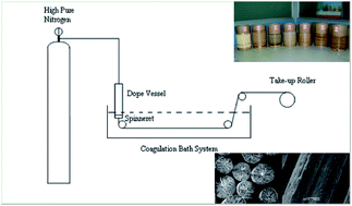
A schematic diagram of the spinning equipment is shown in Fig. 1. The PAN/LS blend dope with one of the different blend ratios was transferred to a dope vessel and maintained at a constant temperature of 60 °C. Then, the blend dope was extruded to a water coagulation bath at room temperature by nitrogen gas, through a spinneret (30 orifices, 120 μm diameter, L/D = 1.5). The blend fibers were collected by a take-up roller at a constant speed. The blend fibers were labeled, as shown in Table 1, where the letters represent different PAN/LS blend ratios.
image file: c5ra01241d-f1.tif
Fig. 1 The schematic diagram of the spinning equipment.
Table 1 Fiber labels of two groups of precursor fibers. The letters represent different blend ratios
1: Dopes with 20% (PAN/LS) concentration
Fiber label A1 B1 C1 D1 E1
PAN/LS (w/w) 100/0 85/15 74/26 65/35 53/47

2: Dopes with 15% PAN content
Fiber label A2 B2 C2 D2 E2
PAN/LS (w/w) 100/0 85/15 74/26 65/35 53/47
Dope concentration 15% 18% 20% 23% 28%


2.4 Characterization methods

The PAN/SL blend fibers were tested by FT-IR (Nicolet, Magna-IR 750). The fibers were vacuum-dried at 60 °C before testing. All the samples were analyzed using the KBr pellet technique and scanned in the range from 4000 to 400 cm−1.

The morphology of the blend fibers and stabilized fibers were investigated by SEM (Hitachi S4800). The blend fibers were immersed in liquid nitrogen and fractured carefully. They were then sputtered with platinum before the SEM observation.18

Tensile test of the blend fibers was performed using a tensile tester (LLy-06E, LLYOD Instrument) in accordance with GB/T 14337-2008 (China). The filament specimen was fixed on a paper holder with an epoxy resin adhesive. The gauge length was 25 mm and crosshead speed was 5 mm min−1.19 The filament diameter was measured using an optical microscope (YS100, Nikon) before the tensile test. Tensile stress was calculated as follows: σ = F/(πd2/4), where σ is the monofilament tensile strength, F is the tensile load and d is the filament diameter. The fiber modulus was obtained according to the stress–strain curve. Every fiber sample was measured 25 times, and the results were averaged.

The blend fibers were cut into small pieces and vacuum-dried at 60 °C. The specimens were measured by TG-DSC using a Netzsch STA 409 PC/PG. TG-DSC scans were run from room temperature to 320 °C at a heating rate of 5 °C min−1 under air atmosphere.

3. Results and discussion

3.1 Interaction between PAN and LS in blend fibers

Fig. 2 presents the FT-IR spectra of the PAN/LS fibers with different blend ratios. The infrared spectrum of LS was tested directly with powder. The peak at 2243 cm−1 is the characteristic absorption peak of –C[triple bond, length as m-dash]N groups in PAN. The peak at 1510 cm−1 corresponds to the skeletal vibration of aromatic rings in LS.9 The peak at 530 cm−1 is the characteristic absorption peak of sulfonyl groups.20 As the PAN/LS blend ratio changed, no new absorption peak was observed in the blend fibers. The characteristic peak position of PAN and LS in the blend fibers did not change significantly. This indicated that there was no chemical crosslinking between PAN and LS in the process of wet spinning.
image file: c5ra01241d-f2.tif
Fig. 2 FT-IR spectra of PAN/LS blend fibers with different blend ratios.

3.2 Morphology of PAN/LS blend fibers

In wet spinning process, the spinning dope entered the coagulation bath through the spinneret and was coagulated by water. In the coagulation bath, the counter diffusion of DMSO and water in the spun fibers influenced their microscopic structures as well as their mechanical properties. The dope concentration and the blend ratio determined the path of liquid–liquid demixing in the coagulation process;21 therefore, the ideal fiber structure could be obtained through controlling these factors. Fig. 3 presents the morphology of the first group of blend fibers, in which the dope concentration is 20%. Column (a) shows the continuously spooled fibers with different PAN/LS ratios.
image file: c5ra01241d-f3.tif
Fig. 3 Morphology of the first group of PAN/LS blend fibers, in which the dope concentration is 20%. The columns show the fiber morphology at different scales. The rows represent different PAN/LS ratios (w/w). (a) Continuously spooled fibers. (b) SEM images of fiber surface. (c) SEM images of fiber cross-section. (d) SEM images of fiber cross-section under high magnification.

The compatibility of the polymer blend is the key factor that decides the blend structure.22 Column (b) in Fig. 3 shows the SEM images of the surface of the PAN/LS blend fibers. Macrophase separation usually in immiscible blends was not found. All the fibers presented a uniform cylindrical structure independent of blend ratio. These results indicated that PAN and LS had very good compatibility. One reason for this was that some of the –OH groups on lignin were replaced by sulfonyl groups, which consequently improved the compatibility of the blend. The other reason was that LS was a type of surface active substance, and thus could adsorb on the macromolecular chains of PAN. Kubo et al.5,23 reported that the melt processing of softwood kraft lignin is difficult even after blending with a plasticizing agent. This also illustrated the poor compatibility between unmodified lignin and polymers.

Column (c) in Fig. 3 provides the SEM images of the fiber cross sections. There was no sea-island structure typically observed in immiscible blends. With the change of the PAN/LS blend ratio, the PAN content in the dope decreased and finger-like pores appeared. The finger-like pores in the SEM images were probably the characteristics of PAN fiber from low dope concentration. The finger-like pores caused a decline in the mechanical properties of fiber, but they could be eliminated by increasing the dope concentration. From column (c), it could be further observed that PAN played a role of “skeleton” in the blend fibers. LS thus attached to the PAN framework. This also showed good compatibility between PAN and LS.

Column (d) in Fig. 3 gives the high-magnification of the area outlined in column (c). As the PAN/LS blend ratio changed from 100/0 (A1) to 53/47 (E1), the microporous structure gradually enriched. The sulfonyl group in LS is a typical hydrophilic group and can influence the counter diffusion process in the coagulation bath, and thus can determine the microscopic structure of the blend fiber. Moderate microvoids were beneficial for the penetration of oxygen into the fibers in the thermal stabilization process.

3.3 Influence of LS on the microstructure of the blend fibers

To investigate the influence of LS on the microstructure of the blend fibers, the dopes with fixed PAN content (15%) were studied. The dope concentration increased from 15% (A2) to 28% (E2), as shown in Table 1. Fig. 4 presents the cross-section morphology of the second group of blend fibers. There were two obvious changes: with the increase of LS content in the dope, the skin of the fiber weakened gradually, and finally disappeared; moreover, the finger-like pores were reduced significantly. Due to the existence of the sulfonyl group in LS, the hydrophilicity of the PAN/LS blend was enhanced. Thus, the macromolecular chains in the spun fiber could stretch fully, and the number of hydrogen bonds between the macromolecular chain and water increased. This effect effectively restrained the diffusion velocity of water (coagulation reagent) and was helpful in generating uniform fiber structure.1 Therefore, the addition of LS could eliminate the structural difference between the skin and the core and reduce the finger-like pores.
image file: c5ra01241d-f4.tif
Fig. 4 The cross-section morphology of the second group of PAN/LS blend fibers. The dopes with fixed PAN content (15%) were used.

3.4 Tensile mechanical properties of PAN/LS blend fibers

Fig. 5 shows the tensile mechanical properties of the two groups of PAN/LS blend fibers. The Young's modulus and tensile strength of the first group of blend fibers decreased rapidly. From PAN/LS ratio of 100/0 (A1) to 53/47 (E1), the fiber modulus decreased from 2.36 ± 0.48 GPa to 0.23 ± 0.01 GPa and tensile strength decreased from 38.14 ± 7.79 MPa to 4.10 ± 0.44 MPa. The mechanical properties of the second group of fibers, however, did not decline very much. As PAN/LS ratio changed from 100/0 (A2) to 53/47 (E2), the fiber modulus decreased from 1.10 ± 0.18 GPa to 0.72 ± 0.04 GPa and tensile strength decreased from 23.08 ± 3.09 MPa to 15.45 ± 0.74 MPa. The Young's modulus of the precursor fiber is the best parameter to represent the CF performance because there is a direct correlation between the Young's modulus of the primary precursor and the resulting CF.18 Considering the tensile mechanical properties and the LS content in the blend fiber, the blend fiber E2 with PAN–LS ratio of 53[thin space (1/6-em)]:[thin space (1/6-em)]47 and dope concentration of 28% may be the best precursor for low-cost CF in this study.
image file: c5ra01241d-f5.tif
Fig. 5 Tensile mechanical properties of two groups of PAN/LS blend fibers.

Higher LS content in the blend fiber means that a decrease in the costs of raw material. From Table 2, blend fiber E1 and blend fiber E2 have the same PAN–LS ratio of 53[thin space (1/6-em)]:[thin space (1/6-em)]47. The increase of dope concentration could improve the mechanical properties of fibers. Comparing picture E1-(c) in Fig. 3 and picture E2 in Fig. 4, the increase of dope concentration improved the structure of the wet-spun fiber. According to Fig. 5 and Table 1, we generated Fig. 6. As shown in Fig. 6, all the comparisons of the modulus and the strength supported the following conclusion. The increase of dope concentration could improve the mechanical properties of the blend fiber. Comparing column (c) in Fig. 3 and 4, with identical blend ratio, the number of finger-like pores of the blend fiber with high dope concentration was less than that of the blend fiber with low dope concentration.

Table 2 The mechanical properties of blend fiber E1 and blend fiber E2
Fiber no. PAN/LS (w/w) Dope con. Modulus Tensile strength
E1 53/47 20% 0.23 ± 0.01 GPa 4.10 ± 0.44 MPa
E2 53/47 28% 0.72 ± 0.04 GPa 15.45 ± 0.74 MPa


image file: c5ra01241d-f6.tif
Fig. 6 Tensile mechanical properties of blend fibers with identical blend ratios but different dope concentrations.

The observation that the increase of dope concentration could improve mechanical properties of the blend fiber with high LS content was very important. In this study, the cost reduction of the precursor fiber came not only from LS (raw material), but also the processing cost (including material processability being improved by increased hydrophilicity and use of a pure water coagulation bath at room temperature). Therefore, the use of PAN/LS blend fibers to prepare a low-cost CF is promising.

3.5 Thermal stability of PAN/LS blend fibers

Fig. 7 shows the TG curves of the PAN/LS blend fibers. The TG curve of LS (F) was measured directly with powder. During the thermal stabilization process, the linear molecular chains of the polymer fiber were transformed into a thermo-tolerant trapezoidal structure, and the fiber morphology was thus maintained.1 From Fig. 7, the weight loss of the blend fibers was not obvious before 250 °C and increased significantly after 250 °C. The PAN fibers (A2) exhibited a weight loss of 5% at 313 °C, and LS powder (F) exhibited a weight loss of 29% at the same temperature. According to the blend ratios and the weight loss of PAN and LS, the theoretical weight loss of the blend fibers was calculated. From Table 3, the actual weight loss was less than the theoretical loss for the blend fibers. This indicated that LS blending with PAN could reduce the fiber weight loss in the thermal stabilization process and increase the thermal stability of the blend fibers.
image file: c5ra01241d-f7.tif
Fig. 7 TG curves of PAN/LS blend fibers.
Table 3 Weight loss of blend fibers at 313 °C
Fiber no. A2 B2 C2 D2 E2 F
Actual weight loss 5% 6% 7% 10% 11% 29%
Theoretical weight loss 5% 8% 11% 13% 16% 29%


The PAN fibers were combined with 8–10% oxygen in the stabilization process. The PAN fibers should be under the presence of oxygen for the formation of a thermo-tolerant trapezoidal molecular structure. The formation of the trapezoidal structure could avoid fracture of the main carbon chain during the carbonization process.1 The oxygen content in lignin was about 30%. The oxygen mainly existed in the form of methoxyl, hydroxyl and carbonyl groups.24 The reduction of the fiber weight loss in this study should be the result of the fact that oxygen in LS promoted the formation of a more trapezoidal structure between PAN and LS.

The DSC curves in Fig. 8 show that all the fibers started the release of a large amount of heat after 200 °C. This should be attributed to the cyclization reaction and oxidation reaction of polymer molecules. As LS content increased, the heat release of the blend fibers increased. The heat release of PAN fiber A2 and the blend fiber B2 was relatively small. This is related to the dense fiber skin, which reduced the rate of oxygen diffusion into the fiber during the thermal stabilization process. As shown in Fig. 3, the fiber skin weakened and the microporous structure enriched with the increase of LS content. The heat release of the blend fibers C2, D2 and E2 increased remarkably, which was benefited from the full penetration of oxygen into the fibers. The instantaneous release of a large amount of heat lead to fiber fusion in the thermal stabilization process.1 PAN/LS blend fiber D2 was stabilized to examine whether the blend fibers could experience a rapid stabilization. The blend fiber was heated to 230 °C at a heating rate of 5 °C min−1 in air stream and held for 2 hours25 in a draught drying cabinet. As shown in Fig. 9, the stabilized fibers still maintained the original fiber morphology, and fiber fusion did not occur. Therefore, PAN/LS blend fibers could be stabilized rapidly without fiber fusion.


image file: c5ra01241d-f8.tif
Fig. 8 DSC curves of PAN/LS blend fibers.

image file: c5ra01241d-f9.tif
Fig. 9 SEM images of the stabilized fibers from blend fiber D2.

4. Conclusion

PAN/LS blend fibers were spun via a wet spinning process. FT-IR spectra showed that there was no chemical crosslinking between PAN and LS in the process of wet spinning. The absence of macrophase separation and sea-island structure in the blend fibers indicated good compatibility between PAN and LS. The addition of LS could weaken the fiber skin and reduce the finger-like pores, and the increasing hydrophilicity of the blend could improve the structure of the wet-spun fibers. The increase of dope concentration could improve mechanical properties of the blend fiber with high LS content. TG curves indicated that LS blending with PAN could reduce fiber weight loss during the thermal stabilization process, and thus increase the thermal stability of the blend fibers. The stabilization experiment showed that the blend fibers could be stabilized rapidly without fiber fusion. Therefore, it is very probable that PAN/LS blend fiber prepared via wet spinning is one of the promising precursors for the production of low-cost CF.

Acknowledgements

The authors would like to acknowledge the support of the National Natural Science Foundation of China (no. 51303199) and the National Natural Science Foundation of China (no. 50602045) for funding this research work.

References

  1. F. He, Carbon Fiber and Graphite Fiber, Chemical Industry Press, Beijing, 2010 Search PubMed.
  2. D. A. Baker and T. G. Rials, J. Appl. Polym. Sci., 2013, 130, 713–728 CrossRef CAS PubMed.
  3. A. J. Ragauskas, G. T. Beckham, M. J. Biddy, R. Chandra, F. Chen, M. F. Davis, B. H. Davison, R. A. Dixon, P. Gilna, M. Keller, P. Langan, A. K. Naskar, J. N. Saddler, T. J. Tschaplinski, G. A. Tuskan and C. E. Wyman, Science, 2014, 344, 709 CrossRef CAS PubMed.
  4. Y. Liang, L. Jin, D. Pan and G. Zhang, Hi-Tech Fiber Appl., 2011, 36, 39–44 CAS.
  5. M. Thunga, K. Chen, D. Grewell and M. R. Kessler, Carbon, 2014, 68, 159–166 CrossRef CAS PubMed.
  6. K. Sudo and K. Shimizu, J. Appl. Polym. Sci., 1992, 44, 127–134 CrossRef CAS PubMed.
  7. L. Yifeng, Hi-Tech Fiber Appl., 2010, 35, 14–19 Search PubMed.
  8. E. Frank, F. Hermanutz and M. R. Buchmeiser, Macromol. Mater. Eng., 2012, 297, 493–501 CrossRef CAS PubMed.
  9. S. P. Maradur, C. H. Kim, S. Y. Kim, B.-H. Kim, W. C. Kim and K. S. Yang, Synth. Met., 2012, 162, 453–459 CrossRef CAS PubMed.
  10. S. Kubo and J. F. Kadla, J. Polym. Environ., 2005, 13, 97–105 CrossRef CAS PubMed.
  11. M. Zhang and A. A. Ogale, Carbon, 2014, 69, 626–629 CrossRef CAS PubMed.
  12. F. Z. Ren, C. X. Lu, X. Y. Liang, G. P. Wu, F. He and L. C. Ling, New Carbon Mater., 2004, 19, 268–274 CAS.
  13. L. M. Ericson, H. Fan, H. Peng, V. A. Davis, W. Zhou, J. Sulpizio, Y. Wang, R. Booker, J. Vavro, C. Guthy, A. N. G. Parra-Vasquez, M. J. Kim, S. Ramesh, R. K. Saini, C. Kittrell, G. Lavin, H. Schmidt, W. W. Adams, W. E. Billups, M. Pasquali, W.-F. Hwang, R. H. Hauge, J. E. Fischer and R. E. Smalley, Science, 2004, 305, 1447–1450 CrossRef CAS PubMed.
  14. N. Behabtu, C. C. Young, D. E. Tsentalovich, O. Kleinerman, X. Wang, A. W. K. Ma, E. A. Bengio, R. F. ter Waarbeek, J. J. de Jong, R. E. Hoogerwerf, S. B. Fairchild, J. B. Ferguson, B. Maruyama, J. Kono, Y. Talmon, Y. Cohen, M. J. Otto and M. Pasquali, Science, 2013, 339, 182–186 CrossRef CAS PubMed.
  15. C. Jiang, A. Saha, C. Xiang, C. C. Young, J. M. Tour, M. Pasquali and A. A. Marti, ACS Nano, 2013, 7, 4503–4510 CrossRef CAS PubMed.
  16. C. M. Jiang, A. Saha, C. C. Young, D. P. Hashim, C. E. Ramirez, P. M. Ajayan, M. Pasquali and A. A. Marti, ACS Nano, 2014, 8, 9107–9112 CrossRef CAS PubMed.
  17. J. J. Hao, C. X. Lu, P. C. Zhou and D. H. Li, Thermochim. Acta, 2013, 569, 42–47 CrossRef CAS PubMed.
  18. A. F. Ismail, M. A. Rahman, A. Mustafa and T. Matsuura, Mater. Sci. Eng., A, 2008, 485, 251–257 CrossRef PubMed.
  19. A. Mataram, A. F. Ismail, D. S. A. Mahmod and T. Matsuura, Mater. Lett., 2010, 64, 1875–1878 CrossRef CAS PubMed.
  20. J. Li, S. Wu and S. Xu, Chem. Ind. For. Prod., 2014, 34, 23–28 CrossRef CAS PubMed.
  21. R. Dong, M. Keuser, J. Zhao, Y. Zhang, C. Wu and D. Pan, Synthetic Technology and Application, 2008, 23, 20–24 Search PubMed.
  22. X. Zhao, L. Du, X. Zhang and J. Zheng, Polym. Bull., 2001, 75–81 CAS.
  23. S. Kubo and J. F. Kadla, J. Appl. Polym. Sci., 2005, 98, 1437–1444 CrossRef CAS PubMed.
  24. T. Jiang, Lignin, Chemical Industry Press, Beijing, 2008 Search PubMed.
  25. L. Z. Zhang, C. X. Lu, Y. G. Lu, G. P. Wu and F. He, New Carbon Mater., 2005, 20, 144–150 Search PubMed.

This journal is © The Royal Society of Chemistry 2015
Click here to see how this site uses Cookies. View our privacy policy here.