Metal–organic framework-derived nickel phosphides as efficient electrocatalysts toward sustainable hydrogen generation from water splitting

Tian Tian, Lunhong Ai* and Jing Jiang*
Chemical Synthesis and Pollution Control Key Laboratory of Sichuan Province, College of Chemistry and Chemical Engineering, China West Normal University, Shida Road 1, Nanchong 637002, P. R. China. E-mail: ah_aihong@163.com; 0826zjjh@163.com; Fax: +86-817-2568081; Tel: +86-817-2568081

Received 5th December 2014 , Accepted 5th January 2015

First published on 6th January 2015


Abstract

Developing robust earth-abundant electrocatalysts for the hydrogen evolution reaction (HER) is an ongoing scientific challenge. The cheap and active metal phosphides have emerged as new candidates for electrochemical HER. Herein, we report on the scalable synthesis of nickel phosphides (Ni2P and Ni12P5) via directly phosphatizing a Ni-based metal–organic framework (MOF) for the first time. The MOF-derived Ni2P nanoparticles exhibited high-performance for electrochemical HER, as manifested by a low overpotential and a large cathodic current density.

Introduction

The extensive utilization of traditional fossil fuels causes severe environmental problems and energy crises. This major concern drives the increased demand for exploring new clean energy sources to meet the sustainability of human society.1,2 Hydrogen appears to be one of the most ideal and cleanest energy sources and is considered as a principal energy carrier for the future,3,4 due to its high gravimetric energy density, ideal combustion efficiency and non-toxicity. However, current production of hydrogen fuel mainly relies on steam reforming and partial oxidation of hydrocarbons, inevitably bringing about large amounts of carbon dioxide emissions. Water electrolysis is an alternative process and a desirable way to produce molecular hydrogen, but both half-reactions of water splitting, namely, the oxygen evolution reaction (OER) and the hydrogen evolution reaction (HER), still remain technical challenges. Although Pt-based electrocatalysts are most active and highly stable for HER, their widespread applications are restricted by the inevitable disadvantages of high price and limited abundance.5 Therefore, it is of great significance to seek earth-abundant alternatives to Pt catalysts to gain a sustainable molecular hydrogen production from water splitting.

At present, several solid-state catalysts composed of earth-abundant elements (e.g. Fe, Co, Ni, and Mo) are selected as versatile candidates for replacement of precious catalysts to achieve high-performance HER activity.6–10 For example, molybdenum sulfides with various structure and tuneable composition have been demonstrated to be one of most active electrocatalysts for the HER.11–14 Very recently, transition-metal phosphides (TMPs), formed by alloying of metals and phosphorus, have attracted intense attention as a new family of HER electrocatalyst. The TMPs including MoP,15–17 FeP,18–20 CoP,21–24 Co2P,25 Cu3P,26 Ni2P27–30 and WP31 have shown promise for HER in strong acidic media with high activity and excellent stability. Among these, the HER behaviour of Ni2P is of especial interest, because Ni2P possesses charged natures similar to those of the hydride acceptor and proton acceptor in [NiFe] hydrogenase and its analogues. Based on density functional theory (DFT) calculation, Rodriguez and Liu have predicted that Ni2P would be an excellent catalyst for HER, because the presence of the proton-acceptor (P site) and hydride-acceptor (Ni site) centers in Ni2P can facilitate catalysis of the HER.32 Such behaviour has been experimentally demonstrated by Popczun et al.27 and Sun et al.28 in various Ni2P nanostructures. Despite these advances, important challenges remain, notably how to produce Ni2P nanostructures in a facile, cost-effective and scalable manner, since most of available synthesis methods normally suffer from complicated operations, special apparatus, harsh conditions and low yield.

Herein, we report a new method to synthesize nickel phosphide nanoparticles with phase selectivity (Ni2P or Ni12P5) by directly phosphating Ni–MOF (Ni–BTC) at a mild condition. This strategy is simple, tunable, inexpensive, and scalable, and is thus highly promising for large scale production. More importantly, we have experimentally demonstrated that the MOF-derived Ni2P nanoparticles would be an excellent candidate of non-precious HER electrocatalyst, showing a low overpotential and high current density.

Experimental

Materials

Sodium hypophosphite and benzene-1,3,5-tricarboxylic acid (BTC) were purchased from Aladdin Ltd. (Shanghai, China). Nickel nitrate, methanol, and H2SO4 were purchased from Kelong Chemical Reagents Company (Chengdu, China). All chemicals used in this study were of commercially available analytical grade and used without further purification.

Synthesis of Ni–BTC metal–organic framework (Ni–MOF)

Ni–BTC metal–organic framework (Ni–MOF) was synthesized according to previous report using methanol as solvent.33 Typically, 4.4 mmol of Ni(NO3)3·6H2O and 2.4 mmol of BTC were dissolved in 70 mL absolute methanol. The mixture was stirred for 1 h at room temperature, and then transferred into a Teflon-lined stainless steel autoclave with a volume capacity of 100 mL and heated at 150 °C for 24 h. After the heat treatment, the autoclave is allowed to cool naturally to room temperature, and the products are collected by centrifugation at 10[thin space (1/6-em)]000 rpm for 5 min and washed with absolute methanol several cycles, and then dried at 60 °C in vacuum 12 h.

Synthesis of nickel phosphides derived from Ni–BTC metal–organic framework

In a typical procedure, 0.1 g of as-prepared Ni–BTC and 0.3 g of NaH2PO2 were mixed together and loaded in a ceramic crucible with a cover and then heated to different temperatures (275 °C for Ni2P nanoparticles and 325 °C for Ni12P5 nanoparticles) with a ramp rate of 5 °C for 1 h in a muffle furnace. After naturally cooling to room temperature, the resulting product was washed with water and ethanol several times and dried in vacuum at 60 °C for 6 h.

Characterization

The powder X-ray diffraction (XRD) measurements were recorded on a RigakuDmax/Ultima IV diffractometer with monochromatized Cu Kα radiation (λ = 0.15418 nm). The Fourier transform infrared (FTIR) spectroscopy was recorded on Nicolet 6700 FTIR Spectrometric Analyzer using KBr pellets. The morphology was observed with the Hitachi S4800 field emission scanning electron microscopes (FESEM) and transmission electron microscope (TEM, FEI Tecnai G20). The elemental composition of the samples were characterized by energy-dispersive X-ray spectroscopy (EDS, Oxford instruments X-Max). X-Ray photoelectron spectroscopy (XPS) measurements were recorded on a Perkin-Elmer PHI 5000C spectrometer using monochromatized Al Kα excitation. All binding energies were calibrated by using the contaminant carbon (C1S = 284.6 eV) as a reference.

Electrochemical measurement

5 mg of nickel phosphide powders was dispersed in 1 mL mixture of distilled water and ethanol (3[thin space (1/6-em)]:[thin space (1/6-em)]1 v/v). Then, 10 μL 5 wt% Nafion was added to the above solution. The mixed solution was sonication at least 30 min to form a homogeneous ink. 5 μL of the mixed solution was drop-casted onto the glassy carbon electrode with the diameter of 3 mm for the electrochemical measurements. All the electrochemical measurements were performed on an electrochemical workstation (CHI 660E, CH Instruments Inc., Shanghai) using a typical three-electrode mode with an electrolyte solution of 0.5 M H2SO4, a Pt wire counter electrode, an Ag/AgCl electrode (saturated KCl) reference electrode, and a modified glassy carbon working electrode. All potentials measured were converted to the reversible hydrogen electrode (RHE) scale according to the Nernst equation: ERHE = EAg/AgCl + 0.197 + 0.059 pH. The polarization curves were obtained by sweeping the potential from 0.2 to −0.8 V (versus the RHE) at room temperature with a scan rate of 5 mV s−1. Chronoamperometric responses were obtained at −170 mV (versus the RHE) in a 0.5 M H2SO4 solution. The current density was calculated by the geometric area of the glassy carbon electrode which is 0.07 cm−2.

Results and discussion

The powder X-ray diffraction (XRD) pattern of the Ni–MOF precursor (Fig. S1, ESI) indicates the amorphous crystalline characteristic, which matches well with previously reported XRD pattern of Ni–BTC.33 The FTIR spectrum further confirm the molecular structure of Ni–BTC (Fig. S2, ESI). SEM images (Fig. S3, ESI) reveal that the Ni–MOF is composed of solid microsphere particles with a diameter of 4.5 μm. Interestingly, the Ni2P nanoparticles can be obtained via a solid chemical transformation from the Ni–MOF precursor by a heat treatment at 275 °C for 1 h. Fig. 1a shows a typical XRD pattern of the MOF-derived Ni2P product. The well-defined diffraction peaks at 40.7°, 44.6°, 47.4°, 54.2°, 54.9°, 66.4°, 72.7° and 74.7° can be perfectly indexed to (111), (201), (210), (300)/(002), (211), (400), (302) and (321) planes of hexagonal Ni2P (JCPDS file no. 89-4864), indicating a good crystallinity and high purity of the product. Fig. S4a displays a low-magnification scanning electron microscopy (SEM) image of the Ni2P product, which reveals that the sample is composed of numerous nanoparticles. These nanoparticles tend to aggregate together and have an average diameter of about 25 nm (Fig. 1b). The compositional analysis carried out by energy dispersive X-ray (EDX) spectroscopy (Fig. 1c) confirms the presence of Ni, P elements and a trace amount of O element. The atomic ratio of Ni to P is estimated to be 1.95[thin space (1/6-em)]:[thin space (1/6-em)]1, which is quite consistent with that of stoichiometric Ni2P (2[thin space (1/6-em)]:[thin space (1/6-em)]1). The corresponding SEM-EDX elemental mapping images (Fig. 1d) further suggest that both Ni and P elements are uniformly distributed in the Ni2P nanoparticles. The detailed microstructure of the Ni2P nanoparticles was further characterized by transmission electron microscopy (TEM). Fig. S4b and c clearly show that the Ni2P product consists of a great deal of aggregated particles with diameters of ∼25 nm. A HRTEM image given in Fig. 1e presents the distance between the lattice fringes is 0.507 nm (see the line profile in Fig. 1f), corresponding to the d-spacing of the (100) plane of the Ni2P. The well-defined lattice fringes in the Ni2P nanoparticles reflect their good crystallinity. The corresponding fast Fourier transform (FFT) pattern (Fig. 1g) shows that the diffraction spots are projected by the (100), (110) and (001) planes, further revealing a hexagonal phase of the Ni2P nanoparticles with good crystallinity.
image file: c4ra15680c-f1.tif
Fig. 1 XRD pattern (a), SEM images (b), EDS spectrum (c), SEM-mapping images (d), HRTEM (e) and corresponding line profile (f) and FFT pattern (g) of the Ni2P nanoparticles.

When phosphidation treatment of Ni–MOF precursor was conducted at a calcination temperature of 325 °C for 1 h, the Ni12P5 nanoparticles with pure phase can be produced. Fig. 2a shows a typical XRD pattern of the MOF-derived Ni12P5 nanoparticles. All diffraction peaks can be indexed as the tetragonal Ni12P5 phase (JCPDS file no. 74-1381). The Ni12P5 nanoparticles exhibit a similar morphology to that of Ni2P nanoparticles, except for the increased particle size up to 80 nm (Fig. 2b and c). A representative TEM image of the Ni12P5 nanoparticles is given in Fig. 2d, from which aggregated nanoparticles can be clearly observed. The corresponding HRTEM image is shown in Fig. 2e. The lattice fringes are ca. 0.253 and 0.305 nm, corresponding to the (002) and (220) crystal planes of high crystalline Ni12P5, respectively. The corresponding FFT pattern (Fig. 2f) shows that the diffraction spots are projected by the (002) and (220) planes, further revealing a tetragonal phase of the Ni12P5 nanoparticles.


image file: c4ra15680c-f2.tif
Fig. 2 XRD pattern (a), SEM images (b and c), TEM image (d), HRTEM image (e) and corresponding FFT pattern (f) of the Ni12P5 nanoparticles.

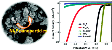
The electrocatalytic activities of the Ni2P and Ni12P5 nanoparticles towards HER were tested by using a typical three-electrode setup in a 0.5 M H2SO4 solution. The working electrode was prepared through loading the catalyst onto a surface (0.07 cm2) of glassy carbon electrode (GCE) with a same mass loading (∼0.35 mg cm−2). Fig. 3a shows the polarization curves of Ni2P and Ni12P5 nanoparticles modified GCE in acid medium. As a comparison, the Ni–MOF, commercial Pt/C catalyst (20 wt%), and bare GCE were also performed under the identical measurements. Pt/C catalyst exhibits the expected HER activity with a near zero overpotential. The bare GCE is totally inactive toward hydrogen generation, while the Ni–MOF shows negligible electrocatalytic performance as well. As for the Ni12P5 nanoparticles, they are able to electrocatalytically produce molecular hydrogen, but a poor HER activity with a high onset overpotential (about 380 mV) and a low cathodic current density is distinctly found. In a sharp contrast, the Ni2P nanoparticles are highly active toward the HER, as evidenced by its small onset overpotential (∼75 mV), large current density and the quickly formed bubbles at the electrode surface under cathodic bias (Fig. S5, ESI). Moreover, above onset overpotential, the cathodic current increases sharply under more negative potentials. Generally, the potential required for the current density of 10 mA cm−2 is a matric relevant to solar fuel synthesis, commonly used to evaluate the HER activity. Of note, the Ni2P nanoparticles can afford such current density at a small η of ∼172 mV, which is lower than that of Ni2P synthesized by using NiCl2 as a Ni-precursor under the same condition (Fig. S6, ESI) and even compare to that of the reported metal phosphides, such as Ni2P nanoparticles,27,29 CoP nanoparticles,22 MoP nanoparticles,16 FeP nanosheets.34


image file: c4ra15680c-f3.tif
Fig. 3 (a) Polarization curves of the Ni2P nanoparticles, Ni12P5 nanoparticles, Ni–MOF, commercial Pt/C catalysts and bare GCE with a scan rate of 5 mV s−1 in 0.5 M H2SO4 solution. (b) Tafel plots of the Ni2P nanoparticles, Ni12P5 nanoparticles and commercial Pt/C catalysts. (c) Capacitive currents at 0.13 V as a function of scan rate for Ni2P and Ni12P5 nanoparticles (Δj0 = jajc). (d) Nyquist plots of the Ni2P and Ni12P5 nanoparticles. (e) Durability test for the Ni2P nanoparticles by CV scanning at different cycles in 0.5 M H2SO4 solution. (f) Continuous hydrogen evolution over Ni2P/GEC electrode at an overpotential of ∼170 mV.

The catalytic kinetics of the Ni2P and Ni12P5 nanoparticles was examined by using Tafel plots (log[thin space (1/6-em)]jη) derived from polarization curves. The linear regions of the Tafel plots are fitted to the Tafel equation (η = b[thin space (1/6-em)]log[thin space (1/6-em)]j + a, where η is overpotential, j is the current density, and b is the Tafel slope). As shown in Fig. 3b, the Tafel slope of 30 mV per decade for Pt/C catalyst agrees with the reported value.27 The Tafel slope of the Ni2P nanoparticles is as low as 62 mV per decade, which is much smaller than that of the Ni12P5 nanoparticles (∼270 mV per decade). The small Tafel slope of the Ni2P nanoparticles benefits them for electrocatalysis of HER, as a smaller Tafel slope would give rise to faster incrementation of the HER rate with increasing overpotential.35–37 The exchange current densities (j0) for the Ni2P and Ni12P5 nanoparticles are further calculated by extrapolating the Tafel plots (Fig. S7, ESI). The Ni2P nanoparticles afford a much larger exchange current density of 0.071 mA cm−2 than that of Ni12P5 nanoparticles (0.045 mA cm−2). The exchange current density is usually expressed in terms of projected or geometric surface area and relative to the surface roughness.26 Therefore, electrochemical surface area of the Ni2P and Ni12P5 nanoparticles was estimated from cyclic voltammetry (CV) (Fig. S8, ESI) at a region without electrochemical reactions by measuring the electrochemical double layer. As shown in Fig. 3c, the capacitance of the Ni2P and Ni12P5 nanoparticles is 2.44 and 1.84 mF cm−2, respectively, which reveals that the Ni2P nanoparticles possess a higher active surface area than Ni12P5 nanoparticles. Also, the electrochemical impedance spectroscopy (EIS) analysis of the Ni2P and Ni12P5 nanoparticles was further performed to understand the electrode kinetics in HER processes. The Nyquist plots given in Fig. 3d reveal a smaller charge transfer resistance of the Ni2P nanoparticles, suggesting the much faster electron transfer process of the Ni2P nanoparticles. This result is consistent with the HER polarization curves of catalysts (Fig. 3a).

The durability of the Ni2P nanoparticles toward the HER was further evaluated by sweeping catalyst for different cycles in 0.5 M H2SO4 solution at a scan rate of 50 mV s−1 (Fig. 3e). The HER activity of the Ni2P nanoparticles shows the slight degradation after each cycle test compared to that of the initial cycle. Additionally, chronoamperometric durability test (Fig. 3f) also presented that the current density is reduced to ca. 75% of initial value in 6 hours. This result is consistent with the previously reported Ni2P nanoparticles.27

Considering that heat treatment is crucial for the transformation of Ni–MOF into nickel phosphides, we further studied how the calcined temperature affected on the HER activity of Ni2P nanoparticles. XRD patterns shown in Fig. S9 suggest that all the samples obtained at the calcined temperatures of 250, 275 and 300 °C are the hexagonal Ni2P. SEM observations indicate that these Ni2P nanoparticles display similar morphology (Fig. S10, ESI). Fig. S11a shows the corresponding polarization curves of these Ni2P nanoparticles toward HER. The HER activity follows the order Ni2P-275 > Ni2P-300 > Ni2P-250. Tafel plots also demonstrate a similar trend, which are calculated to be 231, 62, and 119 mV per decade, for Ni2P-250 Ni2P-275 and Ni2P-300, respectively (Fig. S11b, ESI). Such observations reveal that the calcined temperature controlling could optimize the HER activity of the Ni2P nanoparticles.

Based on previous DFT calculation, the excellent activity of the Ni2P for HER is ascribed to the presence of the proton-acceptor (P site) and hydride-acceptor (Ni site) centers on the surface of Ni2P, which work cooperatively to facilitate the HER.32 As demonstrated by Sun's recent works, the charged natures of Ni and P in Ni2P are analogous to those of proton acceptors and hydride acceptors in [NiFe] hydrogenase and its analogues.28,38 To clarify the origin of the present HER activity, the charged characteristic of the Ni2P nanoparticles was further analysed by the X-ray photoelectron spectroscopy (XPS). As shown in Fig. 4a, three peaks around 852.5, 855.8 and 861.0 eV in the energy level of Ni 2p3/2 correspond to Niδ+ in Ni2P,39 oxidized Ni species and the satellite peak of Ni 2p3/2. There are two peaks in the P 2p XPS spectrum (Fig. 4b). One peak at 129.6 eV can be assigned to P in Ni2P,40 the other peak at 133.5 eV is attributed to oxidized P species.41 Meanwhile, SEM-EDX spectrum (Fig. 1c) also confirms the existence of oxygen in the Ni2P nanoparticles due to superficial oxidation of Ni2P, consistent with previous reported Ni2P.28 Of note, the binding energy (852.5 eV) of Ni in Ni2P is very close to that of zero valence state Ni,41,42 while the binding energy (129.6 eV) of P is negatively shifted from elemental P (130.0 eV),28,38 suggesting that the related Ni and P species in Ni2P have a partial positive charge (δ+) and a negative charge (δ), respectively. This result implies that the HER activity of the Ni2P nanoparticles might be correlated with the intrinsically charged natures of Ni and P. Moreover, the higher δ+ value30,42 and electrical conductivity (Fig. 3d) of Ni2P is critical to the better HER activity compared to the Ni12P5.


image file: c4ra15680c-f4.tif
Fig. 4 XPS spectra of the Ni2P nanoparticles: (a) Ni 2p and (b) P 2p.

Conclusions

In summary, we have synthesized nickel phosphide nanoparticles by solid chemical transformation of Ni–BTC MOF precursor under mild condition. Such economical, earth abundant MOF-derived Ni2P nanoparticles exhibit excellent electrocatalytic activity for the HER with an onset overpotential as low as 75 mV and large cathodic current density, which compare favorably with the HER performance of reported metal phosphides, showing great potential as a low cost alternative to precious Pt catalyst in practical applications. More importantly, our synthetic strategy is simple, tunable, inexpensive, and scalable, and is thus highly promising for large scale production, which can be extended for the general synthesis of other TMPs from MOFs.

Acknowledgements

This work was supported by the National Natural Science Foundation of China (21103141 and 21207108), the Sichuan Youth Science and Technology Foundation (2013JQ0012), and the Research Foundation of CWNU (12B018, 14E016).

Notes and references

  1. S. Zinoviev, F. Muller-Langer, P. Das, N. Bertero, P. Fornasiero, M. Kaltschmitt, G. Centi and S. Miertus, ChemSusChem, 2010, 3, 1106–1133 CrossRef CAS PubMed.
  2. N. Armaroli and V. Balzani, ChemSusChem, 2011, 4, 21–36 CrossRef CAS PubMed.
  3. Z. Y. Lu, H. T. Wang, D. S. Kong, K. Yan, P. C. Hsu, G. Y. Zheng, H. B. Yao, Z. Liang, X. M. Sun and Y. Cui, Nat. Commun., 2014, 5, 4345–4351 CAS.
  4. J. A. Turner, Science, 2004, 305, 972–974 CrossRef CAS PubMed.
  5. C. G. Morales-Guio, L.-A. Stern and X. Hu, Science, 2014, 43, 6555–6569 CAS.
  6. D. Merki, H. Vrubel, L. Rovelli, S. Fierro and X. Hu, Chem. Sci., 2012, 3, 2515–2525 RSC.
  7. Y.-F. Xu, M.-R. Gao, Y.-R. Zheng, J. Jiang and S.-H. Yu, Angew. Chem., Int. Ed., 2013, 52, 8546–8550 CrossRef CAS PubMed.
  8. J. Kibsgaard, Z. Chen, B. N. Reinecke and T. F. Jaramillo, Nat. Mater., 2012, 11, 963–969 CrossRef CAS PubMed.
  9. D. S. Kong, J. J. Cha, H. T. Wang, H. R. Lee and Y. Cui, Energy Environ. Sci., 2013, 6, 3553–3558 CAS.
  10. M. S. Faber, R. Dziedzic, M. A. Lukowski, N. S. Kaiser, Q. Ding and S. Jin, J. Am. Chem. Soc., 2014, 136, 10053–10061 CrossRef CAS PubMed.
  11. D. Merki and X. Hu, Energy Environ. Sci., 2011, 4, 3878–3888 CAS.
  12. A. B. Laursen, S. Kegnæs, S. Dahl and I. Chorkendorff, Energy Environ. Sci., 2012, 5, 5577–5591 CAS.
  13. J. D. Benck, T. R. Hellstern, J. Kibsgaard, P. Chakthranont and T. F. Jaramillo, ACS Catal., 2014, 4, 3957–3971 CrossRef CAS.
  14. Y. Yan, B. Xia, Z. Xu and X. Wang, ACS Catal., 2014, 4, 1693–1705 CrossRef CAS.
  15. P. Xiao, M. A. Sk, L. Thia, X. Ge, R. J. Lim, J.-Y. Wang, K. H. Lim and X. Wang, Energy Environ. Sci., 2014, 7, 2624–2629 CAS.
  16. Z. Xing, Q. Liu, A. M. Asiri and X. Sun, Adv. Mater., 2014, 26, 5702–5707 CrossRef CAS PubMed.
  17. X. Chen, D. Wang, Z. Wang, P. Zhou, Z. Wu and F. Jiang, Chem. Commun., 2014, 50, 11683–11685 RSC.
  18. R. Liu, S. Gu, H. Du and C. M. Li, J. Mater. Chem. A, 2014, 2, 17263–17267 CAS.
  19. Y. Liang, Q. Liu, A. M. Asiri, X. Sun and Y. Luo, ACS Catal., 2014, 4, 4065–4069 CrossRef CAS.
  20. P. Jiang, Q. Liu, Y. Liang, J. Tian, A. M. Asiri and X. Sun, Angew. Chem., Int. Ed., 2014, 53, 12855–12859 CrossRef CAS PubMed.
  21. P. Jiang, Q. Liu, C. Ge, W. Cui, Z. Pu, A. M. Asiri and X. Sun, J. Mater. Chem. A, 2014, 2, 14634–14640 CAS.
  22. Q. Liu, J. Tian, W. Cui, P. Jiang, N. Cheng, A. M. Asiri and X. Sun, Angew. Chem., Int. Ed., 2014, 53, 6710–6714 CrossRef CAS PubMed.
  23. J. Tian, Q. Liu, A. M. Asiri and X. Sun, J. Am. Chem. Soc., 2014, 136, 7587–7590 CrossRef CAS PubMed.
  24. E. J. Popczun, C. G. Read, C. W. Roske, N. S. Lewis and R. E. Schaak, Angew. Chem., Int. Ed., 2014, 53, 5427–5430 CrossRef CAS PubMed.
  25. Z. Huang, Z. Chen, Z. Chen, C. Lv, M. G. Humphrey and C. Zhang, Nano Energy, 2014, 9, 373–382 CrossRef CAS PubMed.
  26. J. Tian, Q. Liu, N. Cheng, A. M. Asiri and X. Sun, Angew. Chem., Int. Ed., 2014, 53, 9577–9581 CrossRef CAS PubMed.
  27. E. J. Popczun, J. R. McKone, C. G. Read, A. J. Biacchi, A. M. Wiltrout, N. S. Lewis and R. E. Schaak, J. Am. Chem. Soc., 2013, 135, 9267–9270 CrossRef CAS PubMed.
  28. Z. Pu, Q. Liu, C. Tang, A. M. Asiri and X. Sun, Nanoscale, 2014, 6, 11031–11034 RSC.
  29. Z. Jin, P. Li, X. Huang, G. Zeng, Y. Jin, B. Zheng and D. Xiao, J. Mater. Chem. A, 2014, 2, 18593–18599 CAS.
  30. A. R. J. Kucernak and V. N. N. Sundaram, J. Mater. Chem. A, 2014, 2, 17435–17445 CAS.
  31. J. M. McEnaney, J. C. Crompton, J. F. Callejas, E. J. Popczun, C. G. Read, N. S. Lewis and R. E. Schaak, Chem. Commun., 2014, 50, 11026–11028 RSC.
  32. P. Liu and J. A. Rodriguez, J. Am. Chem. Soc., 2005, 127, 14871–14878 CrossRef CAS PubMed.
  33. L. Liu, H. Guo, J. Liu, F. Qian, C. Zhang, T. Li, W. Chen, X. Yang and Y. Guo, Chem. Commun., 2014, 50, 9485–9488 RSC.
  34. Y. Xu, R. Wu, J. Zhang, Y. Shi and B. Zhang, Chem. Commun., 2013, 49, 6656–6658 RSC.
  35. J. Xie, H. Zhang, S. Li, R. Wang, X. Sun, M. Zhou, J. Zhou, X. W. Lou and Y. Xie, Adv. Mater., 2013, 25, 5807–5813 CrossRef CAS PubMed.
  36. J. Xie, S. Li, X. Zhang, J. Zhang, R. Wang, H. Zhang, B. Pan and Y. Xie, Chem. Sci., 2014, 5, 4615–4620 RSC.
  37. J. Xie, J. Zhang, S. Li, F. Grote, X. Zhang, H. Zhang, R. Wang, Y. Lei, B. Pan and Y. Xie, J. Am. Chem. Soc., 2013, 135, 17881–17888 CrossRef CAS PubMed.
  38. P. Jiang, Q. Liu and X. Sun, Nanoscale, 2014, 6, 13440–13445 RSC.
  39. P. E. R. Blanchard, A. P. Grosvenor, R. G. Cavell and A. Mar, Chem. Mater., 2008, 20, 7081–7088 CrossRef CAS.
  40. Q. Guan, X. Cheng, R. Li and W. Li, J. Catal., 2013, 299, 1–9 CrossRef CAS PubMed.
  41. Z. Huang, Z. Chen, Z. Chen, C. Lv, H. Meng and C. Zhang, ACS Nano, 2014, 8, 8121–8129 CrossRef CAS PubMed.
  42. Y. Pan, Y. Liu, J. Zhao, K. Yang, J. Liang, D. Liu, W. Hu, D. Liu, Y. Liu and C. Liu, J. Mater. Chem. A, 2015, 3, 1656–1665 CAS.

Footnote

Electronic supplementary information (ESI) available. See DOI: 10.1039/c4ra15680c

This journal is © The Royal Society of Chemistry 2015