
Designing the syntheses and photophysical simulations of noncentrosymmetric compounds
Wen-Dan
Cheng
*,
Chen-Sheng
Lin
,
Zhong-Zhen
Luo
and
Hao
Zhang
State Key Laboratory of Structural Chemistry, Fujian Institute of Research on the Structure of Matter, Chinese Academy of Sciences, Fuzhou, Fujian 350002, People's Republic of China. E-mail: cwd@fjirsm.ac.cn; Fax: (+86)591-83714946; Tel: (+86)591-83713068
First published on 1st December 2014
Abstract
In this paper, we describe the preparations of inorganic noncentrosymmetric (NCS) chalcogenides and their infrared nonlinear optical properties. We present a reasonable synthesis of inorganic NCS compounds by considering the genetic development processes of a living organism. The basic unit having an NCS structure is selected as a chromophore of NCS materials. The NCS compounds are obtained from the NCS chromophore development of normal growth. Chromophore development is an alienation process of growth if the NCS compound is not formed by an NCS chromophore. The normal development of the NCS chromophores (SnS4) and (Sn2S3) affords the NCS crystal of Ba7Sn5S15; and the normal development of the NCS chromophores of (BiS5) and (InS4) affords a compound of Ba2BiInS5 maintaining an NCS structure. In both of them, the Ba2+ ions are a charge-compensating agent. The NCS crystals SnGa4Q7 (Q = S, Se) were obtained from NCS chromophores of (GaQ4) and (SnQ4). However, the centrosymmetric (CS) compound of Ba6Sn7S20 was obtained because the development of NCS chromophores of the (SnS4) and (SnS5) is alienated from the normal process of growth. We give more examples of the NCS chromophore development of normal and alienable processes in this paper. For NCS compounds, we have examined their nonlinear optical (NLO) properties of micro-crystals (powders) and the electronic origin of the NLO response. The intensity of second harmonic generation (SHG), laser-induced damage threshold (LIDT), and infrared transparency were measured, and the conversion efficiency, figure of merit (FOM), and energy band structure were calculated for these NCS compound materials. It is found that the NCS materials of SnGa4Q7 (Q = S, Se) possess large conversion efficiencies, high damage threshold and wide transparencies in the mid-infrared region. Moreover, the study of the micro-mechanism elucidates that the stereochemically active lone-pair electrons of Sn2+ can significantly improve the polarity of the [SnQ4] chromophore. Their large NLO responses originate from the covalent interactions of Sn–Q and the cooperative effects of polarities between the chromophores [SnQ4] and [GaQ4]. It is also found that the Ba7Sn5S15 material has type-I phase- matchability, and that the SHG conversion efficiency and FOM are about twice that of AgGaS2 at the saturated particle size (particle size of 150–212 μm). The Ba8Sn4S15 is not a phase-matching material. The SHG intensity and conversion efficiency of Ba8Sn4S15 are separately about 250 times those of α-SiO2, and the SHG intensity and conversion efficiency are separately about 10 times those of AgGaS2 at the particle size of 25–45 μm.
 Wen-Dan Cheng | Prof. Wen-Dan Cheng has a tenured position at Fujian Institute of Research on the Structure of Matter, Chinese Academy of Sciences. He finished his undergraduate study at the Chemical Department of Xiamen University in 1977 and received his M.S. degree from Xiamen University in 1981. He worked as a visiting professor from 08/1998 to 02/1999 at the Department of Physics, Michigan Technological University, as a visiting scholar from 08/1992 to 12/1993 at the Department of Chemistry, Arizona State University and from 08/1987 to 07/1988 at the Department of Chemistry, University of Calgary. His research interests include designing the syntheses of electro-optical, frequency conversion, and thermoelectric materials, and calculations and simulations of their physical properties; modeling of structures and optics for nanoscale materials; simulations of nonlinear optics for fluorescent proteins, and development of calculated simulation methods for physical properties. |
 Chen-Sheng Lin | Chen-Sheng Lin received his B.S. degree in chemistry from the Xiamen University of China in 1991. He obtained his Ph.D. degree in physical material from City University of Hong Kong in 2006. His research interests focus on the simulation of materials science, including nonlinear optical properties of semiconductors, metal surfaces, molecular electronic structure, and crystal structure prediction using first principles method. |
 Zhong-Zhen Luo | Zhong-Zhen Luo was born in 1986 in Gansu, China. He received his BS degree in Materials Physics from Lanzhou University in 2009, and obtained his PhD degree in Materials Physics and Chemistry from Fujian Institute of Research on the Structure of Matter (FJIRSM), Chinese Academy of Sciences in 2014. He joined Prof. Wen-Dan Cheng's group as a research assistant professor in July 2014. His research interests focus on the synthesis, structures and physical properties of infrared nonlinear optical materials. |
 Hao Zhang | Hao Zhang received his B.S. degree in analytical chemistry from the NorthWest University of China in June 1996. He obtained his master's degree in Physics and Chemistry from Fujian Institute of Research on the Structure of Matter (FJIRSM) in 2000. He joined Wen-Dan Cheng's group as a research assistant professor in 2000. His research interests focus on the synthesis, structures and physical properties of infrared and visible nonlinear optical materials. |
Introduction
Noncentrosymmetric (NCS) compounds and their crystals can exhibit a variety of technologically important physical properties, and NCS crystals may become the materials with piezoelectricity, pyroelectricity, ferroelectricity, and second-order nonlinear optical (NLO) response.1 The structural symmetry of a material affects its properties. There are crystallographic interrelationships between the NCS crystal classes2,3 and physical properties, and among the 32 crystal point groups,4 20 NCS groups (21 NCS crystal classes excluding point group 432 (O group)) can exhibit the piezoelectric or NLO effect. It has been noted that all pyroelectric materials have NLO behavior, but the converse is not true. An NLO material can be made into an optical frequency conversion device, and it can broaden the wavelength coverage ranges of the laser spectrum. As is well known, one can distinguish between two classes of laser sources.5 One class includes sources which generate tunable laser radiation directly from gains in gas discharge, solid-state bulk materials or optical fibers, i.e. direct laser radiation sources. The longest wavelength coverage of a direct solid state laser source is limited to only under 3.5 microns. The other class of laser source is based on the frequency conversion of basic laser sources using NLO crystals. It is for this purpose that many NLO crystals have been developed to broaden the wavelength coverage of the laser spectrum. Scientists and engineers constantly explore new NLO materials to solve the development of optical technology demand and twenty-first century scientific and technological challenges. The main progress has taken place during the last two decades following the advancement in near-infrared solid state laser technology and NLO crystals. The second harmonic generation (SHG) parametric down-conversion and up-conversion processes in NLO crystals as well as their combinations have been widely used to fill in gaps in the laser spectrum in which direct laser radiation does not exist or certain operational regimes are impossible from the vacuum ultraviolet (∼150 nm) to the deep mid-IR (middle infrared) ranges.6–9 The coherent mid-IR sources have important applications in science and technology, including the detection and quantification of molecular trace gases,10 medical diagnostics and military systems,11,12 free space optical communication and deep space exploration, etc.5,13,14At present, nonlinear frequency down-conversion is still a powerful method to transform the wavelength of near-IR laser sources to the mid-IR spectral range and generate coherent radiation in all time zones from 3 μm up to 20 μm and above. Non-oxide NLO crystals play a key role, in particular above 5 μm, such as unary, binary, ternary and quaternary arsenides, phosphides, sulfides, selenides or tellurides, and they have been used in such down-conversion devices. During the past ten years, many compounds with large NLO coefficients and wide transparencies in the IR region have been prepared, and they are K2P2Se6,15 Na2Ge2Se5,16 K4GeP4Se12,17 Na0.5Pb1.75GeS4,18 LiGaGe2Se6,19 α- and β-A2Hg3M2S8 (A = K, Rb; M = Ge, Sn),20 Li2In2GeSe6,21 Li2CdMS4 (M = Ge, Sn),22 Ba6Sn6Se13,23 [Zn(H2O)4][Zn2Sn3Se9(MeNH2)],24 K6Cd4Sn3Se13,25 K14Cd15Sn12Se46,26 A6Sn[Zn4Sn4S17] (A = K, Rb, Cs),27 BaGa2GeQ6 (Q = S, Se),28 Pb4Ga4GeQ12 (Q = S, Se),29 Ba4CuGa5Q12 (Q = S, Se),30 Ag2In2Si(Ge)S6,31 Ag0.5Pb1.75Ge(S1−xSex)4,32 ZnxBa2B2S5+x (x ≈ 0.2),33 CsCd4XIII5Q12 (XIII = Ga, In; Q = S, Se),34 and Rb2CdBr2I2.35 All of them have their specific advantages but also some drawbacks. The crystals of AgGaS2, AgGaSe2, ZnGaP2, GaSe and CdSe also have some drawbacks, although they can be obtained from the commercial market.36 The crystals of AgGaS2 and AgGaSe2 have residual absorption, poor thermal conductivity and anisotropic thermal expansion. The crystals of ZnGaP2 have limited transparency due to multi-photon and residual absorption. The GaSe crystal has a very low damage threshold, and CdSe has quite modest birefringence and nonlinearity. Accordingly, the development of new, and the improvement of existing nonlinear crystals are critical for advancing a mid-IR coherent source, in particular, with increasing conversion efficiency and output power.
Drs I. Chung and M. G. Kanatzidis considered that the metal chalcogenides are the most promising source of potential NLO materials with desirable properties, particularly in the IR region.37 A general strategy is suggested to employ NCS chromophores as building units in the design of the syntheses of NLO crystals.38–40 The NCS chromophore includes the distorted polyhedron with a d0 cation center resulting from a second-order Jahn–Teller (SOJT) effect,41–44 polar displacement of a d10 cation center,45 and the stereochemically active lone pair (SCALP) effect of the cation,46–48 and the distorted triangle and tetrahedron.49–52a The NLO crystal materials can also be constructed by the multifold NCS chromophore with different coordinate environments.52b,53 In this paper, we present the reasonable designs of mid-IR NCS crystals by considering the gene development process.
Designs and syntheses of noncentrosymmetric compounds
Optimization of the material chromophore
The NCS chromophore is a fundamental building block (FBB) toward a NCS material. The development of the NCS chromophore will produce an instrumental device, which is through the processes: chromophore → cluster → … → unit cell → single crystal → device. In bio-systems, genetic development is through the processes: gene → genome → … → cell → tissue → organ. There are some common factors between a gene and an NCS chromophore; both are developments from a basic unit toward the purposes of larger dimensions and function. However, their natures are different. A gene is the molecular unit of heredity of a living organism, and it holds the information necessary to build and maintain an organism's cell and pass genetic traits to offspring. The word gene, when applied in non-biological contexts, connotes an FBB toward the purposes of larger dimensions and function.54 Here, we must have a clear understanding that the material chromophore is not a life activity and the gene in bio-systems exists in a vital organ. By considering gene development in biosystems, we present reasonable designs of NCS inorganic materials originating from NCS chromophores. An NCS chromophore of a material has different coordinate structures, which are the distorted triangle, pentagon, n-polygon (n is odd number with ≠1), tetrahedron, octahedron, square pyramid, pentagonal pyramid, triangular bipyramid, pentagonal bipyramid, and other NCS structure geometries as shown in Fig. 1.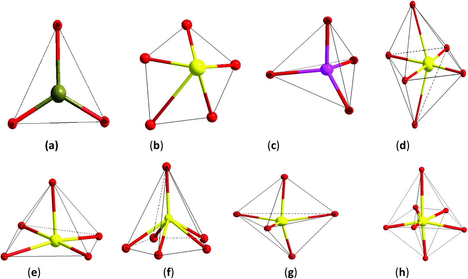 | ||
| Fig. 1 Noncentrosymmetric chromophore structures. (a) Non-equilateral triangle (or triangular pyramid), (b) non-equilateral pentagon, (c) tetrahedron, (d) distorted octahedral, (e) square pyramid, (f) pentagonal pyramid, (g) triangular bipyramid, and (h) pentagon bipyramid. | ||
There can be no guarantee of being able to predict a macroscopic NCS material, which is developed from an NCS chromophore. An NCS chromophore will develop gradually with a normal process of growth if the NCS crystal is constructed using an NCS chromophore. The chromophore development will be an alienation process of growth if the NCS structural crystal is not formed by an NCS chromophore. Such cases have been carefully studied by several groups. Dr Poeppelmeier et al.55–59 synthesized and examined the crystallographically ordered transition-metal oxyfluorides [MOxF6−x]n− (M = d0 transition metal, x = 1–3, and n = 2, 3) and determined that the polar or non-polar symmetry originates from the changes in the bond network. Dr Halasyamani et al. studied another series of analogues A2Ti(IO3)6 (A = Li, Na, K, Rb, Cs, Tl) and considered that the polarity results only from the Li and Na phases of cation-size, coordination requirements, and bond valence concept arguments.60 Our group synthesized the CS crystal of Ba2BiGaS5 and the NCS crystal of Ba2BiInS5, and found that they are constructed by the tetrahedral (Ga/InS4) chromophore and the square-pyramidal (BiS5) chromophore,61 and we consider that the different crystal symmetries result from the distorted tetrahedron or the cation size effect in these two compounds.
CS materials of Ba6Sn7S20, Ba2BiGaS5 and NCS materials of Ba7Sn5S15, Ba2BiInS5
Compound Ba7Sn5S15 was prepared by a solid-state reaction method from stoichiometric amounts of BaS, Sn, and S. It crystallizes in the NCS space group P63cm of the hexagonal system, and is constructed by the material chromophores of the tetrahedron (SnS4) and triangular pyramid (SnS3).62 The Sn–S distances vary from 2.361 to 2.407 Å in the SnS4 tetrahedron, and the calculated bond valence sums (BVS) of the Sn is 4.27 or 4.14, which is close to the oxidation state +4 of Sn. In the triangular pyramidal (SnS3), the Sn has a threefold coordination with Sn–S distances ranging from 2.583 to 2.687 Å, and the calculated BVS is 2.30 or 2.25, which is close to the oxidation state of +2. The two triangular pyramids (2SnS3) are arranged against each other. They share a basal plane and form a triangular bipyramid (Sn2S3). The isolated [SnS4]4− tetrahedra and [Sn2S3]2− triangular bipyramids are held together by the Ba2+ cations.62 The NCS chromophores of (SnS4) and (Sn2S3) develop normally into the NCS crystal, and the skeleton frame is plotted in Fig. 2a. Compound Ba6Sn7S20 was prepared with the molar ratio of stoichiometric amounts of Ba, Sn, and S. It crystallizes in the CS space group C2/c of the monoclinic system, and is constructed by the material chromophores of the tetrahedron (SnS4) and triangular bipyramid (SnS5).62 In the triangular bipyramid, the Sn atom is coordinated by five S atoms with Sn–S distances ranging from 3.339 to 3.812 Å, and the calculated BVS of Sn is 4.09 or 3.96, which is close to the oxidation state +4 of Sn. In the SnS4 tetrahedron, the Sn–S distances vary from 2.327 to 2.481 Å and the calculated BVS of Sn is 3.99 or 4.04, which is also close to the oxidation state +4 of Sn. Three (SnS4) tetrahedra are connected to each other by corner sharing to form a kind of basic structural unit [Sn3S8]4−, and four (SnS5) triangular bipyramids are connected to each other by edge sharing to form another basic structural unit [Sn4S14]12−. Both of the structural units [Sn3S8]4− and [Sn4S14]12− are connected to each other by corner sharing to form a three-dimensional framework with the Ba cations in the cavities in the configuration of the Ba6Sn7S20.62 The development of NCS chromophores of the (SnS4) and (SnS5) is alienated from the normal process of growth, and the CS crystal is obtained as shown in Fig. 2b. By the comparisons between these two processes, we consider that the different crystal symmetries between the Ba6Sn7S20 and Ba7Sn5S15 result from the different oxidation states of Sn ions. We believe that the low oxidation state of Sn ions in the material chromophore (Sn2S3) will be favorable for growing NCS crystals. | ||
| Fig. 2 The skeleton frame of NCS chromophore development (Ba2+ ions are not shown): (a) normal process of chromophores (SnS5) and (SnS4) into Ba7Sn5S20; (b) alienated process of growth into material Ba6Sn7S20 from chromophores (SnS5) and (SnS4). | ||
Compound Ba2BiInS5 was prepared by a solid-state reaction method from stoichiometric amounts of BaS, Bi, In, and S. It crystallizes in the NCS space group Cmc2 of the orthorhombic system, and is constructed by the NCS chromophores of the tetragonal pyramid (BiS5) and the tetrahedron (InS4), and charge-compensating Ba2+ ions.61 The Bi3+ ion is coordinated by five S2− ions, and the bond lengths of Bi–S vary from 2.582(5) to 2.959(4) Å, featuring the irregular tetragonal pyramid (BiS5). In the tetrahedron (InS4), the In3+ ion is coordinated by four S atoms in the tetrahedral arrangement with bond lengths ranging from 2.447(6) to 2.578(6) Å. The edge-shared BiS5 tetragonal pyramids with parallel arrangements are formed into a chain, and the corner-shared InS4 tetrahedra are also formed into a chain. These two chains are further interconnected with each other through sharing corners to form the whole 1∞[BiInS5]4− anionic chain. The NCS chromophores of (BiS5) and (InS4) develop into a compound maintaining an NCS structure, as shown in Fig. 3a. Compound Ba2BiGaS5 was prepared by a solid-state reaction method from stoichiometric amounts of BaS, Bi, Ga, and S. It crystallizes in the CS space group Pnma of the orthorhombic system, and is constructed by the NCS chromophores of the tetragonal pyramid (BiS5) and tetrahedron (GaS4), and charge-compensating Ba2+ ions.61 The coordinate environments of chromophores (BiS5) and (GaS4) in the CS crystal Ba2BiGaS5 are the same as those in the NCS crystal Ba2BiInS5. In the CS crystal Ba2BiGaS5, however, the edge-shared BiS5 tetragonal pyramids with anti-parallel arrangements are formed into a chain, and the tetrahedral GaS4 is connected with the tetragonal pyramid BiS5 by the sharing corner, and the tetrahedra are the alternate arrangements along the chain constructed by the BiS5. Furthermore, they form an infinite one-dimensional (1D) 1∞[BiGaS5]4− anionic chain. The development of the NCS chromophores appears in the alienated process and affords the CS crystal Ba2BiGaS5, as shown in Fig. 3b. It is very interesting that the different crystal symmetries between the CS Ba2BiGaS5 and NCS Ba2BiInS5 are obtained from the same coordinate structure of NCS chromophores of the tetrahedron (GaS4/InS4) and tetragonal pyramid (BiS5). We checked the configurations of these two crystals in detail. A small-sized GaS4 is connected with the neighboring BiS5 through edge-sharing. This situation leads to a trans arrangement along the 1∞[BiGaS5]4− chain with the apexes of BiS5 pyramids reversed up and down alternately, and results in the CS nonpolar structure of compound Ba2BiGaS5. A large-sized InS4 is connected with the neighboring BiS5 through corner-sharing, which results in a cis arrangement along the 1∞[BiInS5]4− anionic chain with the parallel apexes of BiS5 pyramids, and affords the NCS polar structure of Ba2BiInS5.
 | ||
| Fig. 3 The skeleton frame of NCS chromophore development (Ba2+ ions are not shown): (a) normal process of growth from chromophores (BiS5) and (InS4) into material Ba2BiInS5; (b) alienated process of growth from chromophores (BiS5) and (GaS4) into material Ba2BiGaS5. | ||
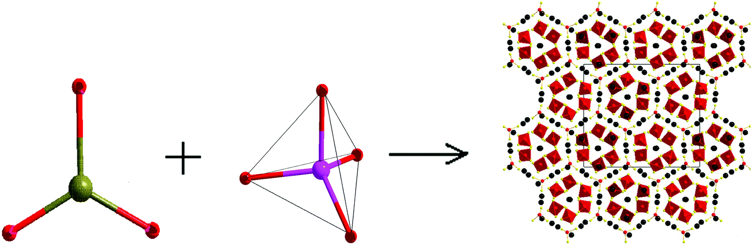
NCS materials of SnGa4Q7 (Q = S, Se) and Ba8Sn4S15 with Sn–Q covalent interactions
Compounds SnGa4S7 and SnGa4Se7 were prepared from reactants of Sn, Ga, and S/Se by a solid-state reaction method at high temperature. Both compounds are crystallized in the NCS space group Pc of the monoclinic system, and the remarkable configurations of three-dimensional frameworks are formed by the tetranuclear secondary basic structural unit Ga4Q11 which is constructed by four GaQ4 tetrahedra, and the SnQ4 tetragonal pyramid located in the cavities.63 In other words, the NCS crystals SnGa4Q7 (Q = S, Se) are constructed by NCS chromophores of the tetrahedron (GaQ4) and tetragonal pyramid (SnQ4), as plotted in Fig. 4. The Sn atom is bonded to four Q atoms at two short and two long distances, forming the SnQ4 tetragonal pyramid, and the Sn–S bond distances range from 2.654 to 2.992 Å in SnGa4S7 and the Sn–Se bonds vary from 2.773 to 3.111 Å in SnGa4Se7. All Ga sites are coordinated by four Q atoms to form the tetrahedra GaQ4. The Ga–S bond lengths range from 2.214 to 2.337 Å in SnGa4S7 and the Ga–Se bonds vary from 2.346 to 2.463 Å in SnGa4Se7. The atomic covalent radii of S, Se, and Sn are individually 1.05(3), 1.20(4), and 1.39(4) Å,64 and here, the bond lengths of Sn–S and Sn–Se are a little larger than the sum of the covalent radius due to the crowd coordination environments of SnG4 (G = S, Se). The calculated ELF (electron localization function) plot shows that there is a charge distribution along the bond axis of Sn–Se (Fig. 5a). This finding indicates the Sn–Se covalent interactions. | ||
| Fig. 4 The skeleton frame of NCS chromophore development of the normal process from (SnS4/Se4) and (GaS4/Se4) into NCS materials of SnGa4Q7 (Q = S, Se). | ||
 | ||
| Fig. 5 (a) The electron localization function map of SnGa4Se7 at the (001) plane cutting through the Sn and Ga atoms and the electron localization function value ranging from 0 (blue) to 1 (red); (b) the charge distributions of the occupied bands near the Fermi level for Ba8Sn4S15 (black, Ba; red, Sn; yellow, S). | ||
Compound Ba8Sn4S15was prepared from a stoichiometric mixture of the BaS–SnS–SnS2 by a solid-state reaction method at high temperature, and it crystallizes in the NCS space group Pca21 of the orthorhombic system.65 The Ba8Sn4S15 crystal is constructed by the NCS chromophores of tetrahedra (SnS4) and pyramids (SnS3) with Ba2+ cations inserted between them for charge balance. Fig. 6 gives the skeleton frame of the chromophore development of the normal process from NCS chromophores (SnS3) and (SnS4). In the tetrahedra SnS4, the Sn–S distances range from 2.3373 to 2.4124 Å, and the calculated BVS of Sn is 4.20 or 4.09, which is close to the oxidation state +4; in the SnS3 pyramids, the Sn–S bond lengths range from 2.5336 to 2.6817 Å, and the calculated BVS of Sn is 1.93, which is close to the oxidation state +2.65 At the right of Fig. 6, the secondary basic structural unit of Ba8Sn4S15 is regarded as a coin-like structure, which forms the two-dimensional (2D) honeycomb structure by an alternate arrangement in parallel. The skeleton of the honeycomb (coin-like configuration) is formed by 6 SnS3 pyramidal units and 18 Ba atoms in the ordered arrangement on the edge and isolated nine SnS4 tetrahedral units and eight Ba atoms fill in the cells of the honeycomb. The charge distributions near the Fermi level are the main contributions from the SnS3 pyramidal units shown in Fig. 5b. This finding also indicates the Sn–S covalent interaction in SnS3.
 | ||
| Fig. 6 The skeleton frame of NCS chromophore development of the normal process from chromophores (SnS3) and (SnS4) into NCS materials of Ba8Sn4S15. | ||
Photophysics simulations and micro-mechanisms of infrared NLO materials
Physical properties
The optical conversion efficiency is the most important standard to evaluate the optical properties of NLO materials. While we select an NLO crystal as frequency conversion devices with a certain laser wavelength, the first option is to require high conversion efficiency. For simplicity of representation, we only consider the SHG process of an NLO response. The SHG conversion efficiency is defined as η = I2ω/Iω, which is a rate of SHG and incident light intensities. The SHG intensity I2ω can be written in terms of the intensity of the incident field according to the couple wave theory, and the expression is written as follows:66a | (1) |
In the MKS system, we can write the conversion efficiency as
| η = CFOMIωL2λω−2PMF, | (2) |
The FOM is determined by the SHG coefficient d and refractive index n of the material, and they can be simulated or calculated by the energy band theory combined with the sum-over-states method67 or the classical anharmonic oscillator model.66b The bulk SHG coefficient, deff, can be estimated by the comparisons between the incident optical intensities of the sample and known material.68 The optical parameters d and n are related to the space structure, charge distribution and transition energy of the crystal material. The FOM is a primary index for the screening of different NLO materials.
Radiation intensity Iω is dependent on the incident optical power P at the fundamental frequency and the cross-sectional area A, and it is in accordance with the relationship Iω = P/A. Accordingly, to obtain the strongest radiation intensity, there must be the largest possible power P and the smallest possible area A if the threshold of the NLO crystal is not a limiting factor. In fact, this situation is not possible, and the threshold is dependent on the optical gap of the material. The latter can be obtained by the calculation of band structures or the measurement of UV–vis diffuse reflectance spectra.69
Additionally, the SHG efficiency can be improved if there is a large L/λω ratio. To obtain a large L/λω ratio, it is necessary for light to pass through the crystal as long as possible or through a large size of crystal and provide a shorter incident wavelength. For a thick crystal (a large L), the maximum ratio L/λω for a given wavelength λω is limited by the thermal conductivity of the material (low thermal conduction leads to heat accumulation and the crystal burst within a large size of crystal). For a thin crystal (very small L), obtaining a large L/λω ratio requires the radiation wavelength to be as short as possible. It is limited by the given wavelength of the radiation source and the anti-damage ability of the material. Accordingly, we require a width window of light transparency in NLO materials. This fact allows us to have a wide coverage of the tunable incident wavelength.
The NLO crystal with high quality laser frequency conversion must meet the conditions of strong radiation intensity Iω, short radiation wavelength λω, long interaction length L, and great figure of merit FOM, which is associated with a high conversion efficiency. Additionally, NLO crystals require: (1) the stability of physical and chemical properties, high hardness, anti-moisture; (2) a good optics uniformity of large-sized crystals; (3) easy processing and low price of crystals, etc. In fact, it is very rare that the NLO crystal is in full compliance with the terms mentioned above. We only select the NLO crystal that meets the most basic conditions according to the application requirement. For example, we require a high conversion efficiency, a large FOM, width infrared transparency including two windows of atmosphere (about 4 and 16 μm), and a large threshold for infrared NLO crystals.
 | ||
| Fig. 7 The SHG intensity vs. particle size of powders (a) SnGa4G7 (G = S, Se) and AgGS2; (b) Ba8Sn4S15, α-SiO2 (inset panel), and AgGaS2. | ||
| Compounds | d 11 | d 12 | d 13 | d 15 | d 24 | d 33 |
|---|---|---|---|---|---|---|
| SnGa4S7 | −6.82 | −2.39 | −3.54 | 9.12 | −10.19 | 15.70 |
| SnGa4Se7 | −4.82 | −1.77 | −5.54 | 18.84 | −13.80 | 37.51 |
The FOM of Ba8Sn4S15 is 250 times that of α-SiO2 and the SHG coefficient deff is estimated to be 6.39 pm V−1 in intensity and localized at the peak (i.e. particle size of 95 μm), with α-SiO2 (dReff = 0.30 pm V−1 (ref. 72)) as a reference in Fig. 7b.65 Additionally, the FOM of Ba8Sn4S15 is 1.12 times that of AgGaS2 and the SHG coefficient deff is estimated to be 14.71 pm V−1 in intensity at a particle size of 180 μm, with AgGaS2 (dReff = 13.9 pm V−1(ref. 71)) as a reference in Fig. 7b.65 The space group of Ba8Sn4S15 belongs to the class mm2, and there are five non-vanishing tensors (d15, d24, d31, d32, and d33) of second-order susceptibility. Under the restriction of Kleinman's symmetry, only three independent SHG tensor components (d31, d32, and d33) are considered. The calculated frequency-dependent SHG coefficients d31, d32, and d33 are plotted in Fig. 8 based on the classical anharmonic oscillator model.65,66b It is found from Fig. 8 that the theoretical values of d31, d32, and d33 are about 23.97, 21.97, and 23.92 pm V−1 at a wavelength of 2.05 μm (0.60 eV), respectively. Note that the theoretical SHG coefficients dij only come from the electronic contributions, not including the contributions from lattice vibrations; and the measured SHG coefficients dij of the powder depend on the particle size. Accordingly, the estimated value of deff based on the experimental measurement must come from the saturated particle size, i.e. SHG intensity is independent of the variation of particle size.
 | ||
| Fig. 8 The calculated frequency-dependent second harmonic generation tensor components for Ba8Sn4S15. | ||
| Compound | Damage energy (mJ) | Spot diameter (mm) | Damage threshold (MW cm−2) |
|---|---|---|---|
| SnGa4S7 | 49.83 | 3.1 | 165.1 |
| SnGa4Se7 | 34.00 | 5.2 | 40.0 |
| Ba8Sn4S15 | 55.37 | 3.8 | 122.1 |
| AgGaS2 | 12.13 (10.05) | 6.7 (8.3) | 8.6 (4.6) |
Micro mechanism of NLO response for infrared materials
 | ||
| Fig. 9 (a) The band structures and (b) total and partial density of states for Ba2BiInS5 using the norm-conserving pseudopotential method. The Fermi level is set at 0.0 eV. | ||
 | ||
| Fig. 10 The partial electron density maps for compound Ba2BiInS5, and the electron density is represented from blue (0.0 e Å−3) to red (0.11 e Å−3). The above DFT calculations were performed using the PAW potential method. | ||
 | ||
| Fig. 11 (a) The band structures and (b) density of states for the Ba7Sn5S15 compound. | ||
 | ||
| Fig. 12 (a) The top view of the electron density contour surface and the dipole moment for isolate [Sn2S3]2−. (b) The arrangement of [Sn2S3]2− in a 2 × 2 unit cell for the Ba7Sn5S15 crystal, the [SnS4]2− group was not shown for clarity. Atom color: S: yellow, Sn: gray, Ba: green. | ||
| Anion group | Dipole moment (Debye) |
|---|---|
| [Sn(1)S4]4− | 1.2359 |
| [Sn(2)S4]4− | 3.0696 |
| [Sn(3)S4]4− | 1.8126 |
| [Sn(4)S4]4− | 1.5062 |
| [Sn(5)S4]4− | 2.0640 |
| [Sn(6)S4]4− | 1.2949 |
| [Sn(7)S3]4− | 11.8679 |
| [Sn(8)S3]4− | 11.5780 |
Summary and prospect
We describe the optimization of NCS chromophores of materials, and present a way of designing the syntheses of inorganic NCS compounds based on the normal processes of development of NCS chromophores. We introduce the alienation process of NCS chromophore development when the NCS compound is not formed by NCS chromophores. We illustrate these concepts by taking actual examples. The NCS chromophores of (SnS4) and (Sn2S3) were normally developed to obtain the NCS crystal of Ba7Sn5S15. The NCS chromophores of (BiS5) and (InS4) were developed into a compound of Ba2BiInS5 maintaining an NCS structure. The NCS crystals SnGa4Q7 (Q = S, Se) were obtained by NCS chromophores of (GaQ4) and (SnQ4). In contrast, the CS compound of Ba6Sn7S20 was obtained because the development of NCS chromophores of the (SnS4) and (SnS5) is alienated from the normal process of growth. We give more examples of NCS chromophore development, which is the normal or alienable process of chromophore growth, in this paper. Here, we only describe the inorganic NCS chalcogenides which are constructed by two chromophores. Moreover, they are constructed by three or multiple NCS chromophores which would be obtained based on the present method.For NCS compounds, we investigate their NLO properties of micro-crystals (powders) and the electronic origin of the NLO response in view of the calculations and simulations. The SHG intensity, laser-induced damage threshold, and infrared transparency were measured. Furthermore, the relative conversion efficiency and figure of merit are derived based on SHG intensity measurements. The calculated charge distributions and local dipole are employed to evaluate the micromechanism of NCS materials. It is found that the NCS materials of SnGa4Q7 (Q = S, Se) possess large conversion efficiencies, high damage threshold and wide transparencies in the mid-infrared region. Also, the study of the micro-mechanism was done to elucidate that the stereochemically active lone-pair electrons of Sn2+ can significantly improve the polarity of the [SnQ4] chromophore. Their large NLO responses originate from the covalent interactions of Sn–Q and the cooperative effects of polarities between the [SnQ4] and [GaQ4] chromophores. It is also found that the Ba7Sn5S15 material has type-I phase-matchability, and that the SHG conversion efficiency and figure of merit are about twice those of AgGaS2 at the saturated particle size (particle size of 150–212 μm). The Ba8Sn4S15 is not a phase-matching material. The SHG intensity and conversion efficiency of Ba8Sn4S15 are separately about 250 times those of α-SiO2, and the SHG intensity and conversion efficiency are separately about 10 times those of AgGaS2 at the particle size of 25–45 μm.
Based upon the requirements of high quality NLO crystals, we believe that the NLO crystals of SnGa4Q7 (Q = S, Se) are in full compliance with the mentioned requisites, and they are good candidates to be applied in laser frequency conversion of the mid-infrared zone. In the future, the key work will be to grow single crystals with sizes larger than 10 mm on the one hand, and on the other hand, to try to prepare transparent films with an NLO response.
Acknowledgements
This investigation was based on work supported by the National Basic Research Program of China (grant no. 2014CB845605) and the National Natural Science Foundation of China (21173225, 91222204 and 21101156).Notes and references
- N. Setter, D. Damjanovic, L. Eng, G. Fox, S. Gevorgian, S. Hong, H. Kohlstedt, A. Kingon, N. Park, G. Stephenson, I. Stolitchnov, A. K. Tagantsev, D. V. Taylor, T. Yamada and S. Streiffer, J. Appl. Phys., 2006, 100, 051606 CrossRef PubMed.
- P. S. Halasyamani and K. R. Poeppelmeier, Chem. Mater., 1998, 10, 2753 CrossRef CAS.
- A. M. Glazer and K. Stadnicka, Acta Crystallogr., Sect. A: Fundam. Crystallogr., 1989, 45, 234 CrossRef.
- T. Hahn, International Tables for Crystallography, D. Reidel Publishing Company, Dordrecht, 1983 Search PubMed.
- F. K. Tittle, D. Richter and A. Fried, Solid-State Mid-Infrared Laser Sources, Topics in Applied Physics, 2003, vol. 89, p. 458, http://link.springer.com/book/10.1007/3-540-36491-9 Search PubMed.
- J. Sakuma, K. Moriizumi and H. Kusunose, Opt. Express, 2011, 19, 15020 CrossRef CAS PubMed.
- H. Zhang, G. Wang, L. Guo, A. Geng, Y. Bo, D. Cui, Z. Xu, R. Li, Y. Zhu, X. Wang and C. Chen, Appl. Phys. B, 2010, 93, 323 CrossRef PubMed.
- K. Kuroda, Y. Toya, T. Satoh, T. Shimura, S. Ashihara, Y. Takahashi, M. Yoshimura, Y. Mori and T. Sasaki, J. Phys.: Conf. Ser., 2010, 206, 012014 CrossRef.
- R. A. Kaindl, M. Wurm, K. Reimann, P. Hamm, A. M. Weiner and M. Woerner, J. Opt. Soc. Am. B, 2000, 17, 12 Search PubMed.
- A. Miklos, C. H. Lim, W. W. Hung, G. C. Liang, A. H. Kung, A. Schmohl and P. Hess, Appl. Opt., 2002, 41, 2985 CrossRef CAS.
- J. Kottmann, J. M. Rey, J. Luginbuehl, E. Reichmann and M. W. Sigrist, Biomed. Opt. Express, 2012, 3, 667 CrossRef CAS PubMed.
- Y. Braiman, http://www.ornl.gov.
- The Herschel space telescope, http://www.esa.int/Our_Activities/Space_Science/Herschel/The_largest_infrared_space_telescope Search PubMed.
- Y. Rumala, The York Scholar, 2006, 3, 52 Search PubMed.
- I. Chung, C. D. Malliakas, J. I. Jang, C. G. Canlas, D. P. Weliky and M. G. Kanatzidis, J. Am. Chem. Soc., 2007, 129, 14996 CrossRef CAS PubMed.
- I. Chung, J.-H. Song, J. I. Jang, A. J. Freeman and M. G. Kanatzidis, J. Solid State Chem., 2012, 195, 161 CrossRef CAS PubMed.
- (a) C. D. Morris, I. Chung, S. Park, C. M. Harrison, D. J. Clark, J. I. Jang and M. G. Kanatzidis, J. Am. Chem. Soc., 2012, 134, 20733 CrossRef CAS PubMed; (b) J. I. Jang, S. Park, C. M. Harrison, D. J. Clark, C. D. Morris, I. Chung and M. G. Kanatzidis, Opt. Lett., 2013, 38, 1316 CrossRef CAS PubMed.
- J. A. Aitken, G. A. Marking, M. Evain, L. Iordanidis and M. G. Kanatzidis, J. Solid State Chem., 2000, 153, 158 CrossRef CAS.
- D. J. Mei, W. L. Yin, K. Feng, Z. S. Lin, L. Bai, J. Y. Yao and Y. C. Wu, Inorg. Chem., 2012, 51, 1035 CrossRef CAS PubMed.
- J. H. Liao, G. M. Marking, K. F. Hsu, Y. Matsushita, M. D. Ewbank, R. Borwick, P. Cunningham, M. J. Rosker and M. G. Kanatzidis, J. Am. Chem. Soc., 2003, 125, 9484 CrossRef CAS PubMed.
- W. Yin, K. Feng, W. Hao, J. Yao and Y. Wu, Inorg. Chem., 2012, 51, 5839 CrossRef CAS PubMed.
- J. W. Lekse, M. A. Moreau, K. L. McNerny, J. Yeon, P. S. Halasyamani and J. A. Aitken, Inorg. Chem., 2009, 48, 7516 CrossRef CAS PubMed.
- K. Feng, X. X. Jiang, L. Kang, W. L. Yin, W. Y. Hao, Z. S. Lin, J. Y. Yao, Y. C. Wu and C. T. Chen, Dalton Trans., 2013, 42, 13635 RSC.
- M. J. Manos, J. I. Jang, J. B. Ketterson and M. G. Kanatzidis, Chem. Commun., 2008, 972 RSC.
- N. Ding, D.-Y. Chung and M. G. Kanatzidis, Chem. Commun., 2004, 1170 RSC.
- N. Ding and M. G. Kanatzidis, Angew. Chem., Int. Ed., 2006, 45, 1397–1401 CrossRef CAS PubMed.
- (a) M. J. Manos, K. Chrissafis and M. G. Kanatzidis, J. Am. Chem. Soc., 2006, 128, 8875 CrossRef CAS PubMed; (b) M. J. Manos, R. G. Iyer, E. Quarez, J. H. Liao and M. G. Kanatzidis, Angew. Chem., Int. Ed., 2005, 44, 3552 CrossRef CAS PubMed.
- X. Lin, Y. Guo and N. J. Ye, Solid State Chem., 2012, 195, 172 CrossRef CAS PubMed.
- Y. K. Chen, M. C. Chen, L. J. Zhou, L. Chen and L. M. Wu, Inorg. Chem., 2013, 52, 8334 CrossRef CAS PubMed.
- S. M. Kuo, Y. M. Chang, I. Chung, J. K. Jang, B. H. Her, S. H. Yang, J. B. Ketterson, M. J. Kanatzidis and K. F. Hsu, Chem. Mater., 2013, 25, 2427 CrossRef CAS.
- A. H. Reshak, I. V. Kityk, O. V. Parasyuk, H. Kamarudin and S. Auluck, J. Phys. Chem. B, 2013, 117, 2545 CrossRef CAS PubMed.
- A. H. Reshak, Y. M. Kogut, A. O. Fedorchuk, O. V. Zamuruyeva, G. L. Myronchuk, O. V. Parasyuk, H. Kamarudin, S. Auluck, K. J. Plucinski and J. Bila, Phys. Chem. Chem. Phys., 2013, 15, 18979 RSC.
- Y. Kim, S. W. Martin, K. M. Ok and P. S. Halasyamani, Chem. Mater., 2005, 17, 2046 CrossRef CAS.
- H. Lin, L. Chen, L.-J. Zhou and L.-M. Wu, J. Am. Chem. Soc., 2013, 135, 12914 CrossRef CAS PubMed.
- Q. Wu, X. Meng, C. Zhong, X. Chen and J. Qin, J. Am. Chem. Soc., 2014, 136, 5683 CrossRef CAS PubMed.
- V. Petrov, Opt. Mater., 2012, 34, 536 CrossRef CAS PubMed.
- I. Chung and M. G. Kanatzidis, Chem. Mater., 2014, 26, 849 CrossRef CAS.
- O. R. Evans and W. Lin, Chem. Mater., 2001, 13, 2705 CrossRef CAS.
- S. D. Bells, M. A. Ratner and T. J. Marks, J. Am. Chem. Soc., 1992, 114, 5842 CrossRef.
- T. K. Bera, J. I. Jang, J. B. Ketterson and M. G. Kanatzidis, J. Am. Chem. Soc., 2009, 131, 75 CrossRef CAS.
- H. S. Ra, K. M. Ok and P. S. Halasyamani, J. Am. Chem. Soc., 2003, 125, 7764 CrossRef CAS PubMed.
- R. E. Sykora, K. M. Ok, P. S. Halasyamani and T. E. Albrecht-Schmitt, J. Am. Chem. Soc., 2002, 124, 1951 CrossRef CAS PubMed.
- (a) E. O. Chi, K. M. Ok, Y. Porter and P. S. Halasyamani, Chem. Mater., 2006, 18, 2070 CrossRef CAS; (b) D. Phanon and I. Gautier-Luneau, Angew. Chem., Int. Ed., 2007, 46, 8488 CrossRef CAS PubMed.
- F. Kong, S. P. Huang, Z.-M. Sun, J. G. Mao and W.-D. Cheng, J. Am. Chem. Soc., 2006, 128, 7750 CrossRef CAS PubMed.
- Y. Inaguma, M. Yoshida and T. Katsumata, J. Am. Chem. Soc., 2008, 130, 6704 CrossRef CAS PubMed.
- S.-H. Kim, J. Yeon and P. S. Halasyamani, Chem. Mater., 2009, 21, 5335 CrossRef CAS.
- D. Phanon and I. Gautier-Luneau, Angew. Chem., Int. Ed., 2007, 46, 8488 CrossRef CAS PubMed.
- H.-Y. Chang, S.-H. Kim, K. M. Ok and P. S. Halasyamani, J. Am. Chem. Soc., 2009, 131, 6865 CrossRef CAS PubMed.
- G.-H. Zou, L. Huang, N. Ye, C.-S. Lin, W.-D. Cheng and H. Huang, J. Am. Chem. Soc., 2013, 135, 18560 CrossRef CAS PubMed.
- Y. Kim, S. W. Martin, K. M. Ok and P. S. Halasyamani, Chem. Mater., 2005, 17, 2046 CrossRef CAS.
- V. V. Badikov, A. G. Tyulyupa, G. S. Shevyrdyaeva and S. G. Sheina, Inorg. Mater., 1991, 27, 177 Search PubMed [Translation from Dokl. Akad. Nauk SSSR, Neorg. Mater., 1991, 27, 248.].
- (a) Y. Kim, I.-S. Seo, S. W. Martin, J. Baek, P. S. Halasyamani, N. Arumugam and H. Steinfink, Chem. Mater., 2008, 20, 6048 CrossRef CAS; (b) T. Yang, J. Sun, J. Yeon, P. S. Halasyamani, S. Huang, J. Hemberger and M. Greenblatt, Chem. Mater., 2010, 22, 4814 CrossRef CAS.
- W.-L. Zhang, W.-D. Cheng, H. Zhang, L. Geng, C.-S. Lin and Z.-Z. He, J. Am. Chem. Soc., 2010, 132, 1508 CrossRef CAS PubMed.
- National Science and Technology Council, Materials Genome Initiative for Global Competiveness, June 2011, http://materialsinnovation.tms.org/genome.aspx.
- P. A. Maggard, C. L. Stern and K. R. Poeppelmeier, J. Am. Chem. Soc., 2001, 123, 7742 CrossRef CAS.
- M. E. Well, A. Norquist, F. P. Arnold, C. L. Stern and K. R. Poeppelmeier, Inorg. Chem., 2002, 41, 5119 CrossRef PubMed.
- P. A. Maggard, T. S. Nault and K. R. Poeppelmeier, J. Solid State Chem., 2003, 175, 27 CrossRef CAS.
- H. K. Izumi, J. E. Kirsch, C. L. Stern and K. R. Poeppelmeier, Inorg. Chem., 2005, 44, 884 CrossRef CAS.
- M. R. Marvel, J. Lesage, J. Baek, P. S. Halasyamani, C. L. Stern and K. R. Poeppelmeier, J. Am. Chem. Soc., 2007, 129, 13963 CrossRef CAS PubMed.
- H. Y. Chang, S. H. Kim, K. M. Ok and P. S. Halasyamani, J. Am. Chem. Soc., 2009, 131, 6865 CrossRef CAS PubMed.
- L. Geng, W.-D. Cheng, C.-S. Lin, W.-L. Zhang, H. Zhang and Z.-Z. He, Inorg. Chem., 2011, 50, 5679 CrossRef CAS PubMed.
- Z.-Z. Luo, C.-S. Lin, W.-D. Cheng, H. Zhang, W.-L. Zhang and Z.-Z. He, Inorg. Chem., 2013, 52, 273 CrossRef CAS PubMed.
- Z.-Z. Luo, C.-S. Lin, H.-H. Cui, W.-L. Zhang, H. Zhang, Z.-Z. He and W.-D. Cheng, Chem. Mater., 2014, 26, 2743 CrossRef CAS.
- B. Cordero, V. Gomez, A. E. Platero-Prats, M. Reves, J. Echererria, E. Cremades, F. Barragan and S. Alvarez, Dalton Trans., 2008, 2832–2838 RSC.
- Z.-Z. Luo, C.-S. Lin, W.-L. Zhang, H. Zhang, Z.-Z. He and W.-D. Cheng, Chem. Mater., 2014, 26, 1093 CrossRef CAS.
- (a) R. W. Boyd, Nonlinear Optics, Academic Press, 3rd edn, 2008, pp. 69–79 Search PubMed; (b) R. W. Boyd, Nonlinear Optics, Academic Press, 3rd edn, 2008, pp. 22–33 Search PubMed.
- (a) D. J. Moss, E. Ghahramani, J. E. Sipe and H. M. van Driel, Phys. Rev. B: Condens. Matter, 1990, 41, 1542 CrossRef CAS; (b) J. L. P. Hughes and J. E. Sipe, Phys. Rev. B: Condens. Matter, 1996, 53, 10 751 CrossRef CAS.
- K. M. Ok, E. Ok Chi and P. S. Halasyamani, Chem. Soc. Rev., 2006, 35, 710 RSC.
- G. Kortüm, Reflectance Spectroscopy, Springer-Verlag, New York, 1969 Search PubMed.
- S. K. Kurtz and T. T. Perry, J. Appl. Phys., 1968, 39, 3798 CrossRef CAS PubMed.
- J.-J. Zondy, D. Touahri and O. Acef, J. Opt. Soc. Am. B, 1997, 14, 2481 CrossRef CAS.
- D. A. Roberts, IEEE J., 1992, 28, 2057 CrossRef CAS.
- J.-Y. Natoli, L. Gallais, H. Akhouayri and C. Amra, Appl. Opt., 2002, 41, 3156 CrossRef CAS.
- K. T. Zawilski, S. D. Setzler, P. G. Schunemann and T. M. Pollak, J. Opt. Soc. Am. B, 2006, 23, 2310 CrossRef CAS.
- C. Xu, S. Yang, J.-F. Wang, J.-N. Niu, H. Ma, Y.-H. Qiang, J.-T. Liu, D.-W. Li and C.-X. Tao, Chin. Phys. Lett., 2012, 29, 084207 CrossRef.
- M. J. Zhang, X. M. Jiang, L. J. Zhou and L. G. C. Guo, J. Mater. Chem. C, 2013, 1, 4754 RSC.
| This journal is © the Partner Organisations 2015 |