 Open Access Article
Improving f-element single molecule magnets
Stephen T.
Liddle
*a and
Joris
van Slageren
*b
aSchool of Chemistry, University of Nottingham, University Park, Nottingham NG7 2RD, UK. E-mail: stephen.liddle@nottingham.ac.uk
bInstitut für Physikalische Chemie, Universität Stuttgart, Pfaffenwaldring 55, D-70569 Stuttgart, Germany. E-mail: slageren@ipc.uni-stuttgart.de
First published on 9th July 2015
Abstract
Ever since the discovery that certain manganese clusters retain their magnetisation for months at low temperatures, there has been intense interest in molecular nanomagnets because of potential applications in data storage, spintronics, quantum computing, and magnetocaloric cooling. In this Tutorial Review, we summarise some key historical developments, and centre our discussion principally on the increasing trend to exploit the large magnetic moments and anisotropies of f-element ions. We focus on the important theme of strategies to improve these systems with the ultimate aim of developing materials for ultra-high-density data storage devices. We present a critical discussion of key parameters to be optimised, as well as of experimental and theoretical techniques to be used to this end.
Key learning points(1) The magnitude of the crystal field splitting is not the only factor determining the slow relaxation of the magnetisation in f-element-based single molecule magnets.(2) Spectroscopic investigations are essential to determining the electronic structures of these systems, and thus a prerequisite for their in-depth understanding. (3) Both crystal-field-based and ab initio methodologies exist for theoretical investigations, and these are complementary. (4) Strongly coupled multi-spin systems are a promising way to obtain substantial magnetic hysteresis and magnetic bistability in zero field. (5) Actinides may more easily deliver strongly coupled systems, especially in combination with transition metals. |
Introduction
In the last decade there has been an exponential increase in the number of publications on molecular compounds of the f-elements that show slow relaxation of the magnetic moment. The idea behind this interest is that a stable magnetic moment can be used to store information at a molecular level. For a typical crystal with unit cell parameters of 1.5 nm, one can easily calculate a two-dimensional data density of almost 300 Tbit per in2. This is to be contrasted to current prototype hard disk models using single-domain magnetic particles that are reaching 1 Tbit per in2. In order for this concept to work, the magnetic moment of the particle needs to be bistable, with an energy barrier between “up” and “down” orientations of the magnetic moment.1 The occurrence of an energy barrier is intimately linked to magnetic anisotropy, which is the phenomenon that a molecule can be more easily magnetized along one direction than along another. In other words, the different orientations of the magnetic moment have different energies. In the absence of orbital angular momentum (e.g., for many transition metal ions), this phenomenon is called zero-field splitting. The orientation of the magnetic moment is then characterized by the mS quantum number. Because for transition metal systems, the second rank axial zero-field splitting (described by the spin Hamiltonian term ) is usually dominant, the potential energy has a parabolic dependence on mS (Fig. 1). For a negative D-value, this leads to an effective energy barrier, where for the magnetic moment to invert, the system must climb a number of steps on one side of the energy barrier and descend on the other. The energy barrier leads to a thermal dependence of the relaxation time, which can be described by the Arrhenius law τ = τ0
![[thin space (1/6-em)]](https://www.rsc.org/images/entities/char_2009.gif) exp(Ueff/kBT). In coordination clusters of first row transition metal ions without orbital angular momenta, the energy barrier ultimately arises from spin–orbit-coupling-induced mixing of the electronic ground and excited states. This is a second order (i.e., small) effect, where the effect is therefore divided by the energy difference between electronic states (∼104 cm−1, i.e., a large number). In contrast, in ions with unquenched orbital angular momenta, spin–orbit coupling induces splittings and therefore magnetic anisotropy in first order. Such ions include low-coordinate transition metal ions,2 as well as f-element ions. This contribution exclusively considers the latter. In this Tutorial Review we examine the reasons why the f-elements are particularly suited to applications in molecular nanomagnetism, provide a commentary on characterisation methodologies, dynamic magnetic phenomena and the various strategies to engineer single molecule magnet (SMM) behaviour, and advance suggestions on how the properties of f-element single molecule magnets can perhaps be improved by design. We focus on the broad lines, referring to the primary literature only in specific cases. The reader is encouraged to refer to the cited books and reviews for further entries into the primary literature.
exp(Ueff/kBT). In coordination clusters of first row transition metal ions without orbital angular momenta, the energy barrier ultimately arises from spin–orbit-coupling-induced mixing of the electronic ground and excited states. This is a second order (i.e., small) effect, where the effect is therefore divided by the energy difference between electronic states (∼104 cm−1, i.e., a large number). In contrast, in ions with unquenched orbital angular momenta, spin–orbit coupling induces splittings and therefore magnetic anisotropy in first order. Such ions include low-coordinate transition metal ions,2 as well as f-element ions. This contribution exclusively considers the latter. In this Tutorial Review we examine the reasons why the f-elements are particularly suited to applications in molecular nanomagnetism, provide a commentary on characterisation methodologies, dynamic magnetic phenomena and the various strategies to engineer single molecule magnet (SMM) behaviour, and advance suggestions on how the properties of f-element single molecule magnets can perhaps be improved by design. We focus on the broad lines, referring to the primary literature only in specific cases. The reader is encouraged to refer to the cited books and reviews for further entries into the primary literature.
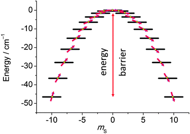 | ||
| Fig. 1 Potential energy as a function of the mS quantum number, calculated using zero-field splitting parameters for Mn12ac. | ||
Slow relaxation in f-elements
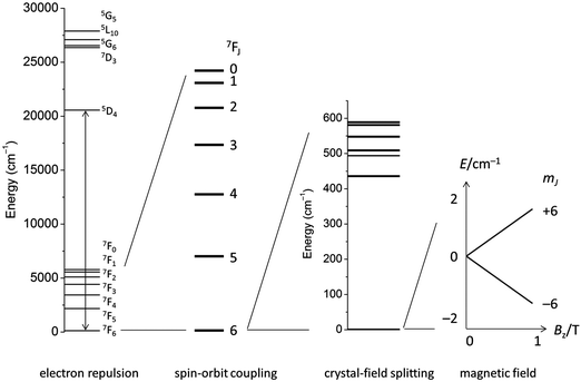
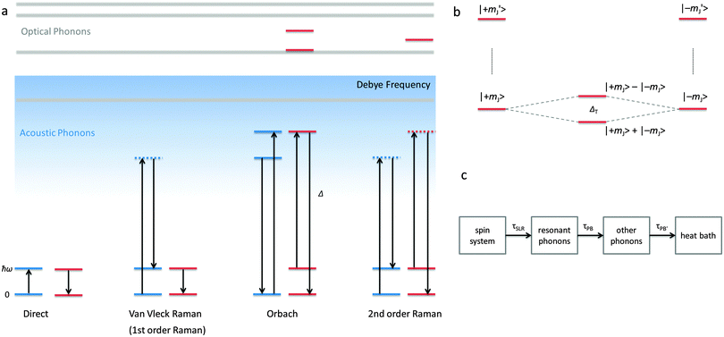
The electronic structure of f-element compounds is profoundly different to that of d-block elements. In the f-block, spin–orbit coupling is much stronger than the crystal field splitting and the magnitude of magnetic anisotropy in f-element compounds arises not from spin–orbit coupling but from the crystal field (CF) splitting, i.e., the electrostatic interactions between the f-electrons and the ligand electrons (Fig. 2). The states resulting from the crystal field splitting are called microstates, which are the mJ states in certain symmetries only (C∞v, D∞h and D4d, all of which are incompatible with the translational symmetry of a crystal), but generally linear combinations of mJ functions. CF splittings in lanthanides can be of the order of hundreds of Kelvins, and in high-oxidation state actinides much larger still.3,4 Indeed, high effective energy barriers, as derived from fitting the temperature dependence of the relaxation time to the Arrhenius law were found in complexes of the lanthanides about a decade ago.5 Since then many molecular compounds of the lanthanides have been found to display slow relaxation of the magnetisation.5 At this point, it is worthwhile to consider a fundamental difference between the relaxation of the magnetisation in a typical 3d polynuclear SMM and a typical 4f single ion magnet (SIM). In the former, the relaxation process consists of many transitions between mS states. The mechanism of the individual steps is in that case of minor importance. In derivations of quantitative relations, it is usually assumed that the energy difference is directly taken up from or given to the lattice (direct process, see below). In contrast, in f-systems, the relaxation often occurs via one or two steps only. One can discuss if the energy barrier picture of Fig. 1 is valid at all in such conditions. In any case, the detailed mechanism of these steps then becomes important. Here we outline the main mechanisms (Fig. 3a). The efficiency and temperature dependence of these processes is different for ions with a half-integer angular momentum (Kramers ions) and for those with an integer angular momentum (non-Kramers ions).In an external magnetic field, there is a small but finite energy difference between the “up” and “down” states. Hence energy must be exchanged with the lattice during the transition from “up” to “down”, to satisfy the law of conservation of energy. All processes which involve exchange of energy between the magnetic ion (the “spin”) and the lattice are termed spin–lattice relaxation. There are three main such processes (Fig. 3): (i) direct relaxation. Here the molecule makes a direct transition from one crystal field microstate to another, and the energy difference is taken up by the lattice as a single quantum of a long-wavelength lattice vibration, also known as an (acoustic) phonon. Note that for Kramers ions, if the two states involved are mirror images of each other in terms of mJ composition (time-reversal conjugate), the transition matrix element must be zero (van Vleck cancellation). The density of states at the relevant energies (∼1 cm−1) is rather small, so not many phonon states are available. This is the reason why, especially at temperatures above that of liquid helium, two-phonon processes become important. These processes involve phonons of higher frequencies, where the density of states is higher. (ii) In the Raman process, the energy released by the relaxing spin system is taken up by a superposition of two lattice waves with a frequency difference that exactly matches that of the released energy. This process can be viewed as a two-phonon process via a virtual intermediate state of the lattice (first order Raman). In the second order Raman process, not only the lattice, but also the spin system undergoes a transition via a virtual intermediate state. (iii) In case the spin system has low lying CF excited states, the Orbach process can occur where absorption of one phonon excites the spin system, followed by relaxation of the spin system to the CF ground state accompanied by emission of a phonon. This process can be viewed as a concerted two-phonon process akin to resonance Raman or as two sequential one-phonon steps with energy conservation in both steps.
The molecular relaxation processes all have their distinct temperature dependences. The full formula for the relaxation rate of the magnetisation as a sum of the three processes outlined above is given in eqn (1):6
 | (1) |
It is important to note here that only the Orbach process has an exponential temperature dependence, which leads to a straight line in the Arrhenius plot of ln![[thin space (1/6-em)]](https://www.rsc.org/images/entities/char_2009.gif) τ vs. 1/T.
τ vs. 1/T.
The central assumption in eqn (1) is that the phonon spectrum of the lattice can be approximated by the Debye model, which is the phononic equivalent of Planck's model of black body (photon) radiation. This model from solid state physics assumes that the density of phonon states depends quadratically on the phonon frequency up to a maximum frequency, which is called the Debye frequency. The Debye frequency represents the maximum acoustic phonon frequency of a crystal. Acoustic phonons are lattice vibrations that have long wavelengths (e.g., 300 nm for a 10 GHz frequency) compared to interatomic distances. A legitimate question is to what extent the Debye model is relevant for complex molecular solids.7 It turns out that that phonon density of states follows that predicted by the Debye model up to perhaps 20 cm−1,7 while above that, the density of states is smaller than that expected. In addition to acoustic phonons, there are also optical phonons, which include all local molecular vibrational modes. In extended ionic lattices, these will have rather high frequencies. However, in molecular solids there are many low energy deformation modes. These optical phonons can then take the place of the acoustic phonons in the Raman and Orbach processes. Optical phonons have been proposed to be responsible for the relaxation via the second excited state in [(Dy)4K2O(OtBu)12] (Fig. 4).8 In principle, optical phonons occur at discrete frequencies, so their participation in the Orbach mechanism should depend on the energy coincidence between the CF energy gap and the optical phonon frequency. Of course, low energy librational (small oscillatory rotational motions of a molecule or a side group around the equilibrium position) and similar motions are perhaps not well defined, so at low frequencies a quasi-continuum of optical phonons may be present.
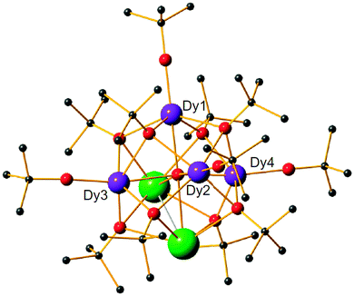 | ||
| Fig. 4 Structure of [(Dy)4K2O(OtBu)12] with hydrogen atoms omitted for clarity. Reprinted by permission from Macmillan Publishers Ltd, ref. 8, copyright 2013. | ||
Finally, the microscopic mechanism of spin–lattice relaxation must involve an oscillating magnetic field, which can induce transitions between microstates. This magnetic field might be thought to originate from the modulation of magneto–dipolar interaction between magnetic ions by phonons (Waller mechanism). However, it was shown that the modulation of the crystal field by phonons is a much more effective mechanism. The modulation of the crystal field leads to an oscillating electric field, which spin–orbit coupling turns into an effective oscillating magnetic field.6 It is usually assumed that the same parameters that describe the static crystal field splitting also describe the oscillating (dynamic) crystal field splitting. However, low-symmetry vibrations will clearly induce low-symmetry components in the dynamic part of the crystal field splitting. But if this is ignored, the crystal field splitting can be developed in a power series of the strain (displacement of the ligand atoms from their equilibrium positions). In that case, calculating the matrix elements of the crystal field Hamiltonian between the different microstates  serves to give a first indication of how effective the Orbach process will be. The effect of distortion along normal coordinates on the crystal field splitting and the microstate composition can be assessed by performing CASSCF calculations in equilibrium and distorted geometries.9
A detailed derivation of the spin–phonon coupling, considering both linear lattice strains and local rotations of the lattice shows that the spin–phonon coupling Hamiltonian to lowest order (relevant for the direct process) contains terms of the type  , where α, γ, ξ, ζ are x, y, z; Λ the spin–phonon coupling coefficients and u the displacement.1 With up to 81 possible coefficients, the situation for quantitative analyses is quite hopeless. However, spin phonon coupling matrix elements
  can be considered to give an indication of the efficiency of spin–lattice relaxation processes between states m and n.10 There are three types of such matrix elements, namely those of the type Ĵz2, those of the type ĴxĴz and ĴyĴz and those of the type Ĵx2, Ĵy2 and ĴxĴy, which induce transitions between doublets with mJ contributions that differ by ΔmJ = 0, ±1 and ±2, respectively.1
It turns out that the matrix elements between states with opposite projections of the magnetic moment (“up” and “down” states) are very small if the anisotropy axes in two doublets are collinear.11 Because spin–phonon interaction elements are important for direct, Raman as well as Orbach processes, collinearity of anisotropy axes will render all of these processes less efficient for transitions between “up” and “down” states. Collinearity of anisotropy axes in different doublets can therefore be considered a design criterion.
In the absence of a magnetic field, there will usually be two such levels with opposite orientations of the magnetic moment (“up” and “down” states) that have (almost) equal energies (Fig. 3b). For ions with half integer angular momenta this is necessarily so, as a consequence of Kramers theorem, which states that crystal field levels in such ions must be at least twofold degenerate.6 If there is a transverse interaction which couples the two levels, then quantum tunnelling can occur (see below), which leads to relaxation of the macroscopic magnetisation. Such transverse interactions include (i) low-symmetry components of the crystal field, (ii) any effective transverse magnetic field, (iii) hyperfine interactions with nuclear spins. The first of these is excluded in Kramers ions. The second can lead to efficient relaxation in non-dilute systems, which is why lanthanide complexes are often diluted into a diamagnetic isostructural complex of yttrium, lanthanum or lutetium. The third is currently thought to play a major role in relaxation of the magnetic moment in (dilute) lanthanide compounds, where it leads to fast relaxation close to zero field, leading to usually negligible coercivity. However, even in isotopically pure (I = 0) SMMs, only very limited coercivity could be observed.12 The same was observed in dilute samples of compounds of 238U which has no nuclear spin at all.13 The open question is therefore what causes the efficient relaxation close to zero-field in these systems.
The transverse interaction causes the eigenstates of the system to be symmetric and antisymmetric superpositions of the “up” and “down” states, where the energy difference (tunnel splitting, ΔT) corresponds to the rate with which the system can tunnel from one side to the other. A general expression for the tunnelling rate τ−1 from a state m on one side of the energy barrier to a state m′ on the other is:1
 | (2) |
 , with τm and τm′ the transition times between levels on the separate sides of the energy barrier; Em − Em′ is the energy difference between the levels on both side of the energy barrier. Through this last term, the tunnelling rate is field dependent. Reducing all unknown quantities to fit parameters, eqn (2) can be simplified to:14
 | (3) |
 will be very small and tunnelling suppressed, as evidenced by small matrix elements
  between states m and n of opposite projections of the magnetic moment (“up” and “down”). These matrix elements are often called transition magnetic moments and expressed in units of μB in the literature.10 This leads to the design criterion of the necessity of axial g values for good SMM performance (see below).11
A final effect that must be considered is the phonon bottleneck.6 This phenomenon is not of molecular origin, but can lead to butterfly-shaped magnetic hysteresis curves. As a consequence of the magnetic relaxation process, phonons emitted to the lattice. For the direct process, the energies of these phonons are the same as the energy difference between “up” and “down” states and can are thus named resonant phonons. Through anharmonicities of the lattice, the resonant phonons couple to other phonon modes and the excitation energy is transferred to these other phonon modes with a certain time constant. Finally, the thermal energy represented by the phonons is transferred to the surroundings (heat bath), which is usually the cryostat in which the measurements are made. If either of these processes is slower than the spin–lattice relaxation rate, phonons will build up in the lattice, leading to thermal excitation of other spins, which prevents further relaxation. This phenomenon is called the phonon bottleneck, and occurs in dense magnetic systems, because the density of spin states is much higher than the density of phonon states at low energies.6
Theoretical description of crystal field splittings
The original theoretical description of CF splitting in lanthanides is due to Stevens, and uses the so-called (extended) Stevens operators,15i.e., operators where the spatial coordinates have been replaced by angular momentum operators, leading to a CF Hamiltonian of the form . Such a description is by definition limited to a single Russell–Saunders multiplet. The lanthanide spectroscopy community long ago adopted a more complete description, where electron correlation, spin–orbit coupling and CF splitting are all taken into account at the same level (Wybourne notation).3,15 Such theoretical models have great value in describing the energy spectrum of the compound under study and in determining the eigenstates of the system. This information then also allows understanding of the (static) magnetic properties. It is important to realise that the details of the coordination geometry are more relevant than any pseudo-symmetry axis. In the words of Gerloch “While idealizations of real molecular geometries to various high symmetry types may occasionally form an adequate basis for approximate studies of optical spectra, they are almost always totally unacceptable for interpretations of paramagnetism, of any quality.”16
A chemist, however, would like to correlate the electronic structure to the geometric structure of the compound and derive structure–property relations. This would then enable the development of improved materials. This desire resulted in approaches such as the superposition model or the angular overlap model, where ligands are characterized by a number of parameters that are hopefully transferable from one complex to the other.17 The general assumption of such models is that the influence of the ligands on the CF splitting is additive, i.e. their contributions are independent of each other. Secondly, the parameters are purely phenomenological, i.e., the parameters are least-squares fitted from experimental data. One can also try to calculate the effect of the CF from first principles, employing models ranging from basic electrostatic models to high level ab initio calculations.
Now, what perspective and possible applications do these methods have? In this consideration, it is important not to overstate the usefulness or applicability of a given model or approach. Furthermore, the usefulness of any model in terms of material improvement is its predictive power, i.e., is it able to give useful insight into how to change a system in order to improve its properties. Can the model provide a blueprint of how to increase the CF splitting in f-element SIMs? We consider now the various currently popular theoretical models and methods:
(i) The electrostatic model.18 The model is based on the fact that the shape of the f-electron-density distribution is aspherical for the Hund's rule ground states of the free ions, but, more importantly, is also a function of the mJ state.19 Thus, for the mJ = ±J states of the most commonly used ions in single ion magnets, the electron density distribution is oblate (pancake-shaped) for terbium(III) and dysprosium(III), but prolate (cigar-shaped) for erbium(III) and ytterbium(III). The mJ = J state has the largest magnetic moment, and thus stabilizing this state in a given complex can be expected to lead to larger crystal field splittings and a better chance of observing single molecule magnet behaviour. Thus for dysprosium and terbium, the ligand geometry should be strongly axial with ligand electron density confined to an axis. An example is the recent study of [ZnCl(μ-L)Dy(μ-L)ClZn][ZnCl3(CH3OH)]·3CH3OH (Fig. 5).20 Although the complex features a square antiprism geometry, two pairs of charged phenoxyl groups are located on opposite sides of the metal ion, resulting in strong axiality of the crystal field. As a consequence, zero-field slow relaxation of the magnetisation is observed and an Arrhenius fit of the temperature dependence of the relaxation time yielded an effective energy barrier of Ueff = 140 K (τ0 = 1.4 × 10⁻⁷ s). Much higher energy barriers are predicted for truly axial systems, such as the fictitious molecule DyO+ (Ueff > 3000 K),11 as well as for two-coordinate Dy-complexes (Ueff > 1000 K).21 In contrast, for erbium the ligand electron density should be localized in a plane. A recent example of the latter is the complex [Er{N(SiMe3)2}3] for which an effective energy barrier of Ueff = 122 K (τ0 = 9.33 × 10⁻⁹ s) was found.22 This complex has crystallographic trigonal symmetry, with ligands located exclusively in the equatorial plane (Fig. 6). In contrast the energy barrier of a similar complex, trigonal bipyramidal [Er{NHPhiPr2}3(THF)2], is only Ueff = 25 K (τ0 = 6.44 × 10⁻⁸), and even then only upon application of an external field. The authors ascribe this difference in behaviour to the axial coordination of two THF ligands in the latter complex.
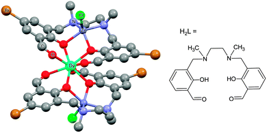 | ||
| Fig. 5 Molecular structure of [ZnCl(μ-L)Dy(μ-L)ClZn][ZnCl3(CH3OH)] with hydrogen atoms omitted for clarity. Taken from ref. 20. | ||
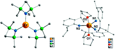 | ||
| Fig. 6 Molecular structures of the complexes [Er{N(SiMe3)2}3] (left) and [Er{NHPhiPr2}3(THF)2] (right), with hydrogen atoms omitted for clarity. Adapted with permission from ref. 22. Copyright 2014 American Chemical Society. | ||
The electrostatic model takes the positions of the coordinating atoms and their formal charges (based on Lewis structure considerations) and from that calculates the energy of the mJ = J state with maximum magnetic moment as a function of the orientation of the ion. The output of the model is the preferred orientation of the CF quantisation axis in a given (low symmetry) coordination geometry. It can explain this orientation in terms of the positions and charges of the surrounding ligands. In terms of predictive power, one can explore how to change the coordination geometry in order to stabilise the magnetic moment along a desired direction. Beyond the general oblate/prolate design criteria, so far the electrostatic model appears to have been used mainly to compare the preferential orientation of the magnetic moment predicted by the electrostatic model and CASSCF calculations to that found in single-crystal SQUID magnetometric measurements. For example in the complex [Dy3(8-quinolinolate)9], there is a good agreement between the orientations of the local easy axes as determined from the electrostatic model and CASSCF calculations (Fig. 7).23 Its limitations are also clear: if the ground doublet does not consist of reasonably pure ±mJ levels, the model does not work. It is also as yet unclear how to deal with uncharged ligands, e.g. water. Finally, a purely electrostatic model cannot be expected to reproduce the entire CF energy spectrum. In the words of Newman of the superposition model: “The inadequacies of the electrostatic model only begin to appear when attempts are made to calculate the values of the phenomenological CF parameters from the distribution of sources of the electrostatic field. There are many such attempts in the literature… …and we wish here only to point out that they have all failed.”17
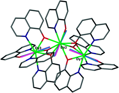 | ||
| Fig. 7 Magnetic anisotropy axes for [Dy3(8-quinolinolate)9]. Blue rods are from ab initio calculations, while pink rods are from electrostatic calculations. Hydrogen atoms are omitted for clarity. Reprinted with permission from ref. 23. Copyright 2014 American Chemical Society. | ||
(ii) The effective charge model.24 This model takes two or three parameters for each of the coordinating atoms, namely an effective charge, an effective radial distance along the line between metal ion and the coordinating atom, and an effective displacement perpendicular to that axis. These parameters are all free fit parameters. The temperature dependence of the magnetic susceptibility is used to find values for the resulting parameters, by grid search of the fit parameters. A recent example of the application of this model is that of [Er(Cp*)(COT)] (Cp* is the pentamethylcyclopentadienyl anion, COT is the cyclooctatetraene dianion) (Fig. 8).25 In this investigation, in order to avoid overparametrization, the properties of the two types of ligands were assumed to be very similar. Thus both displacement factors were taken to be equal for both ligand types. In addition, the charge was assumed to be spread equally among the coordinating atoms of each ligand. With these restraints and using the low-temperature crystal structure, a good fit of the magnetic susceptibility is obtained. The authors then proceed to predict the crystal field splittings of {Nd(COT)[HB(3,5-Me2pz)3]} and [Nd(Cp*)3], using previously obtained effective charge model parameters. Interestingly, they obtain total crystal field splittings and splitting patterns that are similar to those obtained from spectroscopic methods. Potentially, the effective charge model can become as useful as the angular overlap model has been for transition metals. The bottleneck is likely to lie in the determination of robust transferable parameters for a wide range of ligands. This would involve the synthesis and study of a large number of complexes, ideally homoleptic ones with high symmetries. Through extensive magnetic and spectroscopic studies it would then be possible to derive the exact energy spectrum, which in turn would enable deriving reliable effective distances and charges. These values could then be used to design and tailor the coordination geometry around a given lanthanide, in order to maximise the CF splitting between the ground and first excited (quasi-) doublets. Thus far, parameters have been reported for polyoxotungstate, phthalocyanine, trispyrazolyl borate, pentamethylcyclopentadienyl, cyclooctatetraene dianion, and halogen ions.24,25 Other, often used ligands include β-diketonates, amides and polypyridyls, and in-depth studies of lanthanide complexes of these would certainly expand the applicability of the effective charge model.
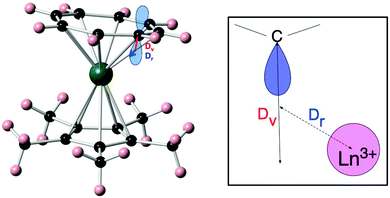 | ||
| Fig. 8 Molecular structure of [Er(Cp*)(COT)] (left) and a schematic depiction of the physical meaning of the radial (Dr) and vertical (Dv) displacement parameters (right). Reprinted with permission from ref. 25. Copyright 2014 American Chemical Society. | ||
(iii) CASSCF calculations.26 An approach has recently become viable is that of using high-level ab initio calculations. Such calculations for f-element based SMMs were pioneered by Chibotaru and Ungur and they have since spawned a school of disciples.27 Briefly, the calculational procedure starts from a CASSCF calculations on a spin-free basis, where the active space consists of the f-orbitals. The resulting eigenfunctions are taken as input for a restricted active space calculation, which takes into account spin–orbit coupling, which results in spin–orbit eigenfunctions that are linear combinations of the spin-free functions. In a final step, a suitable number of eigenfunctions is projected onto a pseudospin ![[S with combining tilde]](https://www.rsc.org/images/entities/i_char_0053_0303.gif) . To extract the ground multiplet CF splitting, this pseudo-spin corresponds to the total angular momentum quantum number of the Russell–Saunders ground multiplet. For determination of the principal g values of a Kramers doublet, a pseudospin
. To extract the ground multiplet CF splitting, this pseudo-spin corresponds to the total angular momentum quantum number of the Russell–Saunders ground multiplet. For determination of the principal g values of a Kramers doublet, a pseudospin ![[S with combining tilde]](https://www.rsc.org/images/entities/i_char_0053_0303.gif) = ½ is used. While these calculations might be expected to yield a rather precise description of the eigenstates and their energies, performing these calculations successfully is by no means trivial. In addition, calculations are typically too costly to be used as a means to “play around”, by trying other ligands and varying R-groups and so on, to generate larger energy gaps. Having said that, first CASSCF studies of the rational design of f-element SMMs are now appearing in literature.21 In this example, the dependence of the effective energy barrier of a (fictitious) two-coordinate complex [Dy{N(SiH3)2}2]+ was calculated as a function of N–Dy–N angle (Fig. 9). It was found that the energy barrier changes from an impressive 2000 cm−1 at 0° to ca. 300 cm−1 at 90°. Also the energy barrier is rapidly diminished by coordination of solvent molecules to the central metal ion. There have also been a number of examinations of series of complexes, carried out with the aim of elucidating the origin of the SIM behaviour, a recent example of which is the study by Aravena and Ruiz.28 These authors calculated the CF splitting of 20 dysprosium(III) complexes, both SIMs and non-SIMs. They find that complexes that behave as SIMs fall into one of two categories. In the first, the dysprosium ion is heteroleptically coordinated, typically by a combination of charged and uncharged ligands. The charged and uncharged ligands generate regions of high and low electrostatic potentials, which serves to pin the easy axis in the direction of the charged ligands. The second category consists of the sandwich complexes, which usually have a lower anisotropy.
= ½ is used. While these calculations might be expected to yield a rather precise description of the eigenstates and their energies, performing these calculations successfully is by no means trivial. In addition, calculations are typically too costly to be used as a means to “play around”, by trying other ligands and varying R-groups and so on, to generate larger energy gaps. Having said that, first CASSCF studies of the rational design of f-element SMMs are now appearing in literature.21 In this example, the dependence of the effective energy barrier of a (fictitious) two-coordinate complex [Dy{N(SiH3)2}2]+ was calculated as a function of N–Dy–N angle (Fig. 9). It was found that the energy barrier changes from an impressive 2000 cm−1 at 0° to ca. 300 cm−1 at 90°. Also the energy barrier is rapidly diminished by coordination of solvent molecules to the central metal ion. There have also been a number of examinations of series of complexes, carried out with the aim of elucidating the origin of the SIM behaviour, a recent example of which is the study by Aravena and Ruiz.28 These authors calculated the CF splitting of 20 dysprosium(III) complexes, both SIMs and non-SIMs. They find that complexes that behave as SIMs fall into one of two categories. In the first, the dysprosium ion is heteroleptically coordinated, typically by a combination of charged and uncharged ligands. The charged and uncharged ligands generate regions of high and low electrostatic potentials, which serves to pin the easy axis in the direction of the charged ligands. The second category consists of the sandwich complexes, which usually have a lower anisotropy.
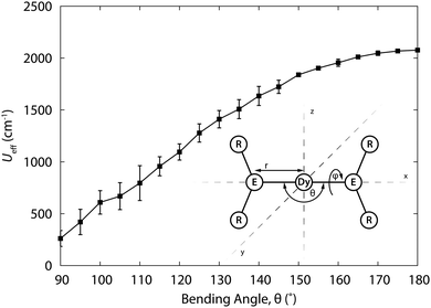 | ||
| Fig. 9 Relaxation barrier Ueff for [Dy{N(SiH3)2}2]+ as a function of the bending angle θ, averaged for all torsion angles ϕ. Structure of the model complex. Adapted with permission from ref. 21. Copyright 2015 American Chemical Society. | ||
So how accurate are CASSCF calculations? The majority of comparisons to experiment have involved comparing the CF splitting direction from the CASSCF calculations with that derived from single crystal magnetometry. In many cases good agreement was found, but there have also been cases where the agreement was not satisfactory.29 In the few cases that comparison with spectroscopy has been possible, deviations of the order of 10–20 cm−1 have been found,30 which in relative terms can be a deviation of 30%. There are two directions in which CASSCF calculations can be improved. Firstly, the geometry is typically not optimised and hence the calculation is only as good as the experimental structure. This is usually obtained at ca. 100 K, whilst magnetic and spectroscopic measurements are typically carried out at much lower temperatures. Therefore, there is scope for low-temperature crystallographic work in this area. Secondly, dynamic electron correlation (CASPT2 or similar) is typically not considered. Clearly, improvements in program packages and computer hardware will give more possibilities here.
Historical perspective
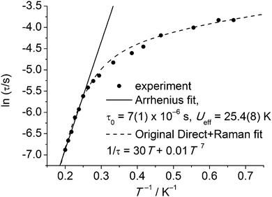
Slow relaxation in extended lattice compounds of the lanthanides has been studied intensively from the 1960s and even earlier.6 In those days, a (limited) number of compounds were studied in great detail, e.g., Ln2Mg3(NO3)12, LnF3, LnCl3·6H2O, Cs2NaYCI6, and Ln(C2H5SO3)3·9H2O. Often, samples were prepared by doping minute amounts of the lanthanide ion of interest into an isostructural diamagnetic lattice. The last of these compounds is closest to a molecular complex, and better formulated as [Ln(H2O)9](C2H5SO3)3 (LnES, Fig. 10). The complex ions [Ln(H2O)9]3+ form a hydrogen bonded network with the ethyl sulfate counter ions. Spin–lattice relaxation times were determined for virtually all of the series Ce–Yb.31 Typically, these measurements involved either microwave saturation recovery methods in an applied magnetic field, or mutual inductance ac susceptometry with or without applied dc fields. Of the investigated ethyl sulfates, the Yb and Tb-derivatives show slow relaxation in zero dc field, and are therefore possibly the first examples of lanthanide-based SIMs. However, the relevance of the Orbach mechanism (and thus of the energy barrier picture) is not necessarily obvious. To reinforce this point, Fig. 11 shows the original32 zero-field relaxation data for 1% Tb3+ in [Y(H2O)9](C2H5SO3)3 as ln![[thin space (1/6-em)]](https://www.rsc.org/images/entities/char_2009.gif) τ versus T−1, rather than the original log
τ versus T−1, rather than the original log![[thin space (1/6-em)]](https://www.rsc.org/images/entities/char_2009.gif) τ−1versus log
τ−1versus log![[thin space (1/6-em)]](https://www.rsc.org/images/entities/char_2009.gif) T. An Arrhenius fit of the high temperature region gives the very plausible, but unphysical, parameters of Ueff = 25.4(8) K and τ0 = 7(1) × 10−6 s. Although these parameter values are not unusual for lanthanide-based SIMs, they must be wrong, because the lowest excited CF state that can act as the intermediate state lies at 101 cm−1, (determined by optical spectroscopy), clearly much higher than the energy barrier. In addition, Fig. 11 shows the original fit that assumed the combined action of the direct and Raman relaxation processes. In fact, traditionally, if the gap between CF states was found to be higher than 100 K, the Orbach mechanism was traditionally excluded from the analysis of the relaxation.32
T. An Arrhenius fit of the high temperature region gives the very plausible, but unphysical, parameters of Ueff = 25.4(8) K and τ0 = 7(1) × 10−6 s. Although these parameter values are not unusual for lanthanide-based SIMs, they must be wrong, because the lowest excited CF state that can act as the intermediate state lies at 101 cm−1, (determined by optical spectroscopy), clearly much higher than the energy barrier. In addition, Fig. 11 shows the original fit that assumed the combined action of the direct and Raman relaxation processes. In fact, traditionally, if the gap between CF states was found to be higher than 100 K, the Orbach mechanism was traditionally excluded from the analysis of the relaxation.32
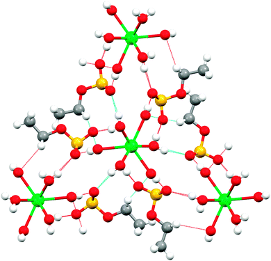 | ||
| Fig. 10 Molecular structure of [Tb(H2O)9](C2H5SO3)3 viewed along the trigonal axis (the viewing direction causes three of the water ligands to be obscured). | ||
The case for spectroscopy
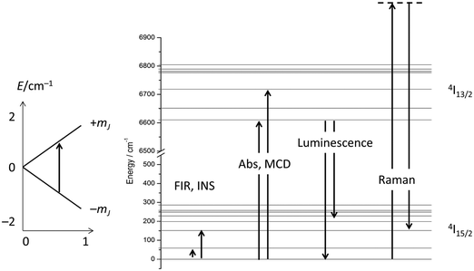
Considering the above four processes (direct, Raman, Orbach, tunnelling), at least six parameters have to be fitted, which, for a gently curved dependence, cannot be expected to lead to an unambiguous parameter set. One solution is to choose experimental conditions in such a way that operation of some of the processes can be excluded, such as working at very low temperatures to exclude two phonon processes, or carrying out measurements in the absence of an external field to exclude the direct process (for Kramers ions).14 Advanced magnetometry methods, such as single-crystal susceptibility or torque magnetometry, also yield additional information.29 Another option is to obtain more information on the electronic structure, and this is what was traditionally chosen in the 1960s and beyond. In fact, the electronic structures of the studied materials were often known in detail before the start of spin dynamics investigations (Fig. 12). Thus, the electronic structures due to the CF splitting were derived from high-resolution optical absorption spectra.33 The positions of the first excited CF-states were verified and confirmed by far infrared spectroscopy.34 In addition, luminescence spectroscopy,35 and magnetic circular dichroism spectroscopy36 were also employed. Electronic Raman scattering measurements appear not to have been successful for the ethyl sulfates, but were used in other lanthanide compounds.37 Spectroscopic measurements serve to unequivocally determine the energetic positions of the CF states in lanthanide single molecule magnets. The comparison of these energies with the energy barrier from relaxation measurement allows determination of whether the Orbach mechanism of spin relaxation is operative or not.Furthermore, it has been shown that: (i) the temperature dependence of the dc susceptibility does not allow determination of electronic structure; and (ii) energies obtained from CASSCF calculations are not always completely accurate and deviations of the order of 30% have been found.30,38 Hence, although theoretical studies are extremely valuable, a thorough experimental determination of the low energy electronic structure is a prerequisite for the development of robust structure–property relationships. Without these, the rational design of improved f-element based single molecule magnets will remain elusive. The experimental determination of the full electronic structure is only possible by spectroscopic means. The importance of spectroscopy in this area is now being realised, and increasingly reports of luminescence, inelastic neutron scattering, and far-infrared spectroscopy are appearing.39 Detailed optical absorption, magnetic circular dichroism or electronic Raman studies in the current era of renewed interest in the CF splitting of f-elements have seemingly not yet appeared but will certainly be essential.
The case for coupled systems
The observation of extremely high effective energy barriers towards the inversion of the magnetic moment in lanthanide complexes that amount to many hundreds of Kelvins appears at first sight to be a major breakthrough in the field of molecular nanomagnetism. However, what matters in the end for data storage applications is the bistability of the magnetic moment in zero applied field, i.e. the magnetisation curve should display hysteresis with substantial coercivity. In this area, molecular f-element complexes generally do not perform well, and coercive fields are typically zero or very close to zero (Fig. 14a and b). The reason for this is that the magnetic moment can tunnel effectively under the barrier, which is enabled by a transverse interaction of some kind (see above). Tunnelling can be suppressed by application of a small external magnetic field, and, indeed, very often slow relaxation of the magnetisation is only observed in finite fields (typically up to several hundreds of mT). Such a small effective field can also be generated by a neighbouring spin (another molecule, another ion, or a coordinated radical ligand), which leads to a shift of the tunnelling step in the hysteresis curve away from zero, hence suppressing tunnelling in zero-field.40 Stronger couplings are found in 4f–2p systems with radical ligands such as nitroxides.41 However, for the improvement of the single-molecule magnet properties, i.e. long magnetisation relaxation times in zero applied field, stronger couplings between lanthanide ions are necessary. Stronger interactions would cause the coupled system to behave as a single magnetic moment, similarly to the giant spin scenario in polynuclear transition metal clusters. The many-body nature of such a system can be expected to limit the rate of quantum tunnelling of the magnetisation. However, because of the contracted nature of the f-orbitals, the interactions of these electrons with their surroundings are limited. As a consequence, any superexchange interactions between f-elements or with transition metal ions tend to be weak, and magnetic coupling is usually of a dipolar nature.A milestone in the area of lanthanide–radical-based SMMs was reached with the report of the N23−–radical bridged lanthanide dimers [{[(Me3Si)2N]2(THF)Ln}2(μ-η2:η2-N2)]− (Ln = Gd, Tb, Dy, Ho, Er; Fig. 13) whose magnetisation remains stable over relatively long periods of time (for Ln = Dy, Tb).42 The energy barriers of 177 K (Dy) and 327 K (Tb) are not unusual for complexes of these lanthanide ions. However, in contrast to all other lanthanide complexes reported up to that point, the reported systems show considerable magnetic hysteresis at field sweep rates of less than a Tesla per minute at temperatures of 7 K (Dy, Fig. 14c and d) and 13.9 K (Tb). What makes these complexes special is that the coupling between the lanthanide ions and the bridging ligand is much stronger (J = −27 cm−1,  for the Gd derivative) than for any other lanthanide–radical complexes (|J| < 5 cm−1).43 This causes the Ln–Rad–Ln unit to behave as a ‘giant spin’, limiting quantum tunnelling of the magnetisation. The reason for such a strong interaction was attributed to the highly diffuse nature of the magnetic orbitals on the radical N23− ligand, which is corroborated by the fact that the less strongly reduced species containing the N22− bridge behaves as conventional lanthanide SMM, and displays strong effects of the quantum tunnelling. In other words, the LnIII–N23− bond has partial covalent character. Exchange coupling has also been reported in the less exotic bipyrimidyl radical complexes of Gd, Tb, and Dy, [(Cp*2Ln)2(μ-bpym˙)](BPh4) (Fig. 13).44 Strong ferrimagnetic (magnetic moments align in an antiparallel fashion, but are not of equal size) exchange coupling is apparent for all three species as evidenced by increases in χMT at low (<50 K) temperatures. For the isotropic Gd complex, where spin–orbit effects are not operative, it was possible to determine antiferromagnetic coupling constant of J = −10 cm−1 giving an S = 13/2 ground state. The Tb and Dy analogues display slow relaxation with energy barriers of 44(2) and 87.8(3) cm−1, respectively, and, more importantly, magnetic hysteresis at temperatures above that of liquid helium. This approach could be rather fruitful, as the complexes are much more manageable than the N23−-ones. One could for example use bridging ligands with lower π*-levels, to stabilise the one-electron reduced bridging ligand.
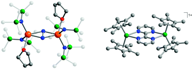 | ||
| Fig. 13 Molecular structures of [{[(Me3Si)2N]2(THF)Ln}2(μ-η2:η2-N2)]− (left, reprinted by permission from Macmillan Publishers Ltd, ref. 42, copyright 2011) and [(Cp*2Ln)2(μ-bpym˙)](BPh4) (right, reprinted with permission from ref. 44. Copyright 2012 American Chemical Society), with hydrogen atoms omitted for clarity. | ||
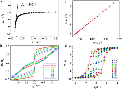 | ||
| Fig. 14 Experimental data for polynuclear dysprosium(III)-based single molecule magnets. (a) Arrhenius plot and (b) hysteresis plot for [(Dy:Y)4K2O(OtBu)12] recorded at a sweep rate of 0.14 T s−1, adapted by permission from Macmillan Publishers Ltd, ref. 8, copyright 2013; (c) Arrhenius plot and (d) hysteresis plot for [K(18-crown-6)]{[(Me3Si)2N]2(THF)Dy}2(μ-η2:η2-N2), recorded at a sweep rate of 0.08 T s−1, adapted by permission from Macmillan Publishers Ltd, ref. 42, copyright 2011. | ||
The theoretical description and experimental determination of magnetic couplings in f-element complexes
In transition metal systems, magnetic couplings are usually described by partial charge transfer of electron density from a closed shell bridging ligand to the d-orbitals of the metal ions it bridges (charge transfer mechanism of superexchange). Other mechanisms, such as spin polarization and double exchange also play a role.45 The exchange interaction depends on the detailed overlap between the orbitals involved, which is reflected in the possibility to devise magnetostructural correlations between the exchange coupling constant and specific bond lengths and angles. Although the exchange interaction could be anisotropic, in practice, it can be usually very well described by an isotropic spin Hamiltonian of the type . The magnetic coupling in lanthanide systems does not usually involve charge transfer into the f-orbitals, which are spatially too constricted. Rather, the unpaired electron is donated into the empty d- or s-orbitals of the lanthanide ion. Hund's rule then suggests that the f-electron spin should be preferentially aligned in a parallel fashion to the spin density of the transferred charge.43 Whilst for gadolinium(III), the magnetic coupling can still be parametrized by means of a spin Hamiltonian, for all other trivalent lanthanide ions this is not possible, on account of the presence of an orbital angular momentum. Thorough descriptions of the coupling between a magnetic centre with orbital angular momentum and any other type of magnetic centre usually yield Hamiltonians featuring orbit–orbit, spin–orbit, and spin–spin interactions, resulting in discouragingly large numbers of parameters to be determined from fitting experimental data.46
A large variety of approximations exist, which have a common aim in trying to eliminate any Hamiltonian term that features orbital angular momentum operators. Usually Kramers ions are considered. The anisotropy of the system that results from the orbital angular momentum (orbitally-dependent exchange) must in some way be reflected by the resulting Hamiltonian. The simplest approach is to model the ions as pseudo-spins ![[S with combining tilde]](https://www.rsc.org/images/entities/i_char_0053_0303.gif) = ½, considering the ground Kramers doublets of each of the ions. The anisotropy is then necessarily reflected in the anisotropy of the exchange interaction:
= ½, considering the ground Kramers doublets of each of the ions. The anisotropy is then necessarily reflected in the anisotropy of the exchange interaction:  . In case of strongly axial anisotropy, the Ising limit with Jz ≠ 0, Jx = Jy = 0 is attained.47 Such an approach can only be valid at temperatures much lower than the gap to the first excited Kramers doublet. An example is the trinuclear dysprosium cluster [Dy3(μ3-OH)2(o-vanillinate)3Cl(H2O)5]Cl3 (Fig. 15).48 In this cluster, the easy axes of the three dysprosium ions are located close to the plane defined by the three ions. As a result, the magnetic ground state has a magnetic moment that is close to zero. In an external magnetic field, the first excited state crosses the ground state, leading to a step in the magnetisation curve. A model, which considers only Ising type interactions
  between the ground doublets of the dysprosium ions is able to reproduce this step. To reproduce the details, it turned out to be necessary to include the first excited doublets.
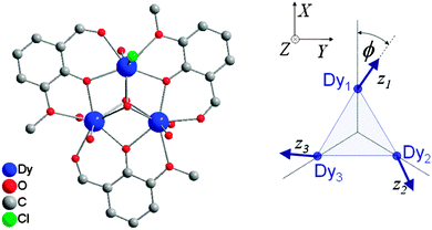 | ||
| Fig. 15 Molecular structure of [Dy3(μ3-OH)2(o-vanillinate)3Cl(H2O)5]3+ with hydrogen atoms omitted for clarity (left) and a scheme depicting the directions of the local easy axes (right). Taken from ref. 48. | ||
A second type of model is that which can be traced to the Lines model. The original model was derived for cobalt(II) ions in strict Oh symmetry, without considering effects of magnetic anisotropy. The exchange interaction between the ground Kramers doublets (treated as pseudo-spins ![[S with combining tilde]](https://www.rsc.org/images/entities/i_char_0053_0303.gif) = ½) is assumed to be isotropic and treated exactly, whilst for the excited doublets the effect of the coupling was reflected in temperature-dependent effective g values and spin expectation values.49 In later adaptations of the Lines model, the effect of low symmetry components of the crystal field was considered.46 More recently, similar modelling approaches have assumed isotropic exchange interactions between the spin components of the angular momenta of two lanthanide ions.38 This is also the approach used in the poly_aniso routine of the MOLCAS programme, where an arbitrary number of Kramers doublets, obtained from fragment calculations on each of the ions, is taken into account.50
= ½) is assumed to be isotropic and treated exactly, whilst for the excited doublets the effect of the coupling was reflected in temperature-dependent effective g values and spin expectation values.49 In later adaptations of the Lines model, the effect of low symmetry components of the crystal field was considered.46 More recently, similar modelling approaches have assumed isotropic exchange interactions between the spin components of the angular momenta of two lanthanide ions.38 This is also the approach used in the poly_aniso routine of the MOLCAS programme, where an arbitrary number of Kramers doublets, obtained from fragment calculations on each of the ions, is taken into account.50
In a recent example, the asymmetric lanthanide dimer [hqH2][Dy2(hq)4(NO3)3] MeOH (hqH = 8-hydroxyquinoline, Fig. 16) was investigated.38 In this compound, the two lanthanide ions are in very different coordination sites. Far-infrared spectra revealed the energies of the first two Kramers doublets of the dysprosium ion in the NO3 pocket to be 39 and 59 cm−1, compared to the CASSCF calculated values of 24 and 39 cm−1. CASSCF calculations showed that there is a large angle of 44° between easy axes of the two ions, which leads to efficient quantum tunnelling and concurrent absence of slow relaxation of the magnetization. However, it proved to be possible to quantify the magnetic coupling by EPR spectroscopy, where both the Dy2 dimer as well as the Y2 dimer, doped with Dy3+ (Dy@Y2) were investigated. In Dy EPR spectra recorded at conventional frequencies (9.7, 24, 34 GHz) revealed a marked difference between Dy@Y2 and Dy2, which is direct evidence of magnetic coupling. The spectra could be fitted well considering two pseudo-spins ![[S with combining tilde]](https://www.rsc.org/images/entities/i_char_0053_0303.gif) = ½ corresponding to the two ground doublets only, and the Hamiltonian
= ½ corresponding to the two ground doublets only, and the Hamiltonian  , where the single ion g tensors were obtained from CASSCF and EPR measurements at conventional and high frequencies on Dy@Y2. The resulting fit parameters were J⊥ = +0.525 and J∥ = +1.52 cm−1, and it was shown that these cannot be due to magnetic dipolar couplings only.
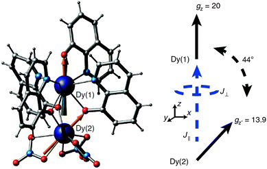 | ||
| Fig. 16 Molecular structure of [hqH2][Dy2(hq)4(NO3)3] (left) and a scheme depicting the directions of the local easy axes. Reprinted from ref. 38. | ||
In order to get an experimental handle on magnetic couplings in lanthanide systems, often the diamagnetic substitution method is employed.51 This method is aimed at separating the effects on the magnetic susceptibility of the weak magnetic coupling from those of the strong crystal field splitting of the lanthanide ion(s). To this end, both the complex of interest and a suitable derivative are considered. In case the complex of interest is a 4f–2p system, the suitable derivative is structurally as similar as possible, but containing a closed shell ligand, rather than the organic radical ligand (e.g., nitrone vs. nitronyl nitroxide). For 4f–3d complexes a diamagnetic transition metal is substituted (e.g. square planar Ni(II) or Zn(II) for Cu(II)). Finally, for asymmetric 4f–4f systems, the diamagnetic rare earth ions yttrium(III), lanthanum(III) and lutetium(III) are used, either in two-step synthesis or in doping approaches.38 The measured susceptibility of the derivative is subtracted from that of the complex of interest, yielding the magnetic response of the second magnetic centre as well as the effects of the coupling. This allows extraction of the nature of the magnetic coupling (ferro-/antiferromagnetic) as well as an estimate of the coupling magnitude. Details on the anisotropy in the magnetic coupling can typically not be obtained, due to the lack of information inherent in powder susceptibility measurements, as well as the fact that diamagnetic substitution can and will influence the coordination geometry of the lanthanide ion. Single crystal susceptibility and spectroscopic measurements, especially electron paramagnetic resonance are both essential for obtaining information on the details of the magnetic coupling.51
The case for actinides
In spite of the above hopeful perspectives, significant covalent lanthanide–ligand bonding character will always be challenging to obtain. Alternatively, the 5f orbitals of actinides are spatially more diffuse than the 4f orbitals of lanthanides and generally energetically better matched to ligand-based orbitals.52 This can be expected to allow greater p–f orbital overlap, and hence stronger magnetic couplings, as well as larger CF splittings. Indeed, the CF at uranium(III) is larger, and that at uranium(V) is much larger (by an order of magnitude), than that of the lanthanides. However, the 5f ions equivalent to the celebrated Tb3+ and Dy3+ are Bk3+ and Cf3+, which are highly radioactive and are annually produced in sub-gram quantities only. The most feasible actinide element for developing new SMMs is uranium which has Russell–Saunders ground states of 4I9/2 (like Nd3+), 3H4 (like Pr3+), and 2F5/2 (like Ce3+) in its +3, +4, and +5 oxidation states, respectively. Indeed, a number of uranium(III)-, and uranium(V)-based SMMs have been reported, with energy barriers of up to 33 K.52,53 Interestingly, slow relaxation of the magnetisation at uranium(III) has been observed in a range of ligand fields of vastly differing symmetries, which suggests that uranium(III) is inherently inclined towards SMM behaviour, albeit with only moderate energy barriers.13 It should be noted that not every uranium(III) complex is an SMM, however. Considerably higher energy barriers, as well as significant magnetic hysteresis were found in systems containing uranyl(V) and six manganese(II) ions.52,53 Since manganese(II) would not be expected to have a sizable anisotropy of its own, the uranyl ions must play a significant role in the magnetisation dynamics. One example is [{[Mn(TPA)I][UO2(Mesaldien)][Mn(TPA)I]}I] (Mn2U) (Fig. 17).54 The dc susceptibility was studied by the subtraction method (see above). To this end the magnetic susceptibility of analogous compound Cd2U was subtracted from that of Mn2U. The result is indicative of significant ferromagnetic interactions between uranyl and manganese ions, as evidenced by the strong increase of χT towards lower temperatures. The ac susceptibility displays a strong out-of-phase signal and the Arrhenius analysis of the data yields an energy barrier of Ueff = 81 ± 0.5 K with a pre-exponential factor of τ0 = 5.02 × 10⁻¹⁰ s. Interestingly, the compound displays magnetic hysteresis at temperatures below 3 K both in the solid state and in solution.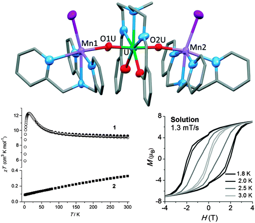 | ||
| Fig. 17 (top) Molecular structure of [{[M(TPA)I][UO2(Mesaldien)][M(TPA)I]}I] (M = Mn (Mn2U), Cd (Cd2U)) with hydrogen atoms omitted for clarity; (bottom left) Susceptibility temperature product as a function of temperature for Mn2U (1) and Cd2U (2), as well as their difference (open symbols), showing the effective ferromagnetic coupling between UVO2 and MnII. (bottom right) Magnetic hysteresis recorded on a pyridine solution of Mn2U. Adapted with permission from ref. 54. Copyright 2014 Wiley-VCH. | ||
Improving f-element SMMs
Is rational design of improved lanthanide SMMs possible? A number of design criteria have been discussed here and reported in the literature, explicitly or implicitly, and we summarize them here. A first step is to engineer the crystal field splitting with the aim to make the quantum tunnelling, Raman, and Orbach relaxation processes all less efficient. Using the prolate/oblate nature of lanthanide ions, the geometries and charges of the coordinating ligands can be designed in such a way that the microstate of the ground multiplet with the largest magnetic moment is stabilized. Quantum tunnelling is minimized by using Kramers ions (with half integer angular momenta), because low symmetry components of the crystal field cannot cause tunnelling. In addition, a highly axial anisotropy of the ground doublet, resulting in negligible transverse g values, will limit tunnelling. This has led to an interest in effectively linear complexes. However, also in low-symmetry surroundings, the ground Kramers doublet can have surprisingly axial anisotropy. Both effective charge models and CASSCF calculations are starting to play and may increasingly play an important role in the design of such systems. We believe a very fruitful avenue will be the development of exchange coupled polynuclear lanthanide clusters with radical bridges and actinide–transition metal clusters, because tunnelling in strongly exchange coupled clusters is many times less efficient than in single ion systems. The efficiency of the Orbach process is limited by increasing the energy gaps to excited microstates. Both Orbach and Raman transitions between “up” and “down” states are quenched by collinearity of the anisotropy axes of the ground and excited doublets. It will be very challenging to engineer such collinearity for many microstates in low symmetry systems, and the number of pseudo-axial systems will therefore probably remain limited.For systems, where the relaxation is a one- or two-step process, the energy barrier picture of Fig. 1 has limited applicability. In such complexes, increasing the crystal field splitting will not necessarily lead to better single-molecule magnets, because other relaxation processes that are not directly dependent on the magnitude of the crystal field splitting (Raman, direct processes) may dominate. This is reflected in reports of easy plane SIMs.55 However, after successful engineering of the crystal field splitting as described above, the relaxation becomes a multistep process. As a consequence, the details of the individual steps become less important and the energy barrier picture of relaxation of magnetisation recovers its validity.
Beyond engineering the CF splitting, the only further possible improvement comes from engineering the spin–phonon coupling itself. One could imagine that a stiffer lattice, which leads to increased spin–lattice relaxation times in solids will also have a beneficial effect on magnetization relaxation times in molecular solids. However, the coupling between ion and lattice is poorly understood on a quantitative level. Also, the role of low-frequency molecular motions that assume the role of optical phonons in Orbach and Raman relaxation processes is as yet unclear. Hence, it is at this stage not possible to derive detailed strategies for improving f-element SMMs in this direction.
Conclusions
Progress in Science happens only when a significant advance of our fundamental understanding of the universe or significant progress toward some application is achieved. Hence, care must be taken not to oversell current results; e.g., the study of spin relaxation in single lanthanide ions is a topic of venerable age and many of the current (field-induced) single ion magnets are in that sense nothing new. From a fundamental point of view, different avenues to increased understanding are open. The ion–lattice interaction leading to slow relaxation is not understood at a quantitative level, and is a very challenging topic. In addition, high-level ab initio calculations, in combination with advanced spectroscopy may enable understanding of f-element complexes with low symmetries to an extent that was impossible before. The detailed understanding of the electronic structure, magnetism and magnetisation dynamics of molecular 5f compounds is virtually virgin territory, but also far from straightforward.Any progress toward the self-professed goal of magnetic data storage has to start by achieving substantial magnetic hysteresis on a more than sporadic scale. Strong magnetic coupling in polynuclear f-element compounds to suppress tunnelling is certainly a key factor in this regard, as is engineering of the crystal field splitting. Only then can there be any hope of achieving the ultimate aim of relaxation times of the order of years in zero field. In uranium(III), so far there appears to be an upper limit of ca. 30 K on the effective energy barrier, but surprises may lie around the corner. Much promise lies also in uranium(V), especially in combination with 3d spin centres.
References
- D. Gatteschi, R. Sessoli and J. Villain, Molecular Nanomagnets, Oxford University Press, Oxford, 2006 Search PubMed.
- G. A. Craig and M. Murrie, Chem. Soc. Rev., 2015, 44, 2135–2147 RSC.
- C. Görller-Walrand and K. Binnemans, in Handbook on the Physics and Chemistry of Rare Earths, ed. K. A. Gschneidner and L. Eyring, Elsevier, Amsterdam, 1996, vol. 23 Search PubMed.
- G. Liu and J. V. Beitz, in The Chemistry of the Actinide and Transactinide Elements, ed. L. R. Morss, N. M. Edelstein and J. Fuger, 2006, vol. 3 Search PubMed.
- D. N. Woodruff, R. E. P. Winpenny and R. A. Layfield, Chem. Rev., 2013, 113, 5110–5148 CrossRef CAS PubMed.
- A. Abragam and B. Bleany, Electron Paramagnetic Resonance of Transition Ions, Dover Publications, Inc., New York, 1986 Search PubMed.
- S. S. Eaton and G. R. Eaton, Biol. Magn. Reson., 2000, 19, 29–154 CrossRef CAS.
- R. J. Blagg, L. Ungur, F. Tuna, J. Speak, P. Comar, D. Collison, W. Wernsdorfer, E. J. L. McInnes, L. F. Chibotaru and R. E. P. Winpenny, Nat. Chem., 2013, 5, 673–678 CrossRef CAS PubMed.
- N. F. Chilton, C. A. P. Goodwin, D. P. Mills and R. E. P. Winpenny, Chem. Commun., 2015, 51, 101–103 RSC.
- L. Ungur, M. Thewissen, J. P. Costes, W. Wernsdorfer and L. F. Chibotaru, Inorg. Chem., 2013, 52, 6328–6337 CrossRef CAS PubMed.
- L. Ungur and L. F. Chibotaru, Phys. Chem. Chem. Phys., 2011, 13, 20086–20090 RSC.
- F. Pointillart, K. Bernot, S. Golhen, B. Le Guennic, T. Guizouarn, L. Ouahab and O. Cador, Angew. Chem., Int. Ed., 2015, 54, 1504–1507 CrossRef CAS PubMed.
- F. Moro, D. P. Mills, S. T. Liddle and J. van Slageren, Angew. Chem., Int. Ed., 2013, 52, 3430–3433 CrossRef CAS PubMed.
- J. M. Zadrozny, M. Atanasov, A. M. Bryan, C.-Y. Lin, B. D. Rekken, P. P. Power, F. Neese and J. R. Long, Chem. Sci., 2013, 4, 125–138 RSC.
- C. Rudowicz and M. Karbowiak, Coord. Chem. Rev., 2015, 287, 28–63 CrossRef CAS PubMed.
- M. Gerloch, Magnetism and ligand field analysis, Cambridge University Press, Cambridge, 1983 Search PubMed.
- D. J. Newman and B. Ng, Rep. Prog. Phys., 1989, 52, 699 CrossRef CAS.
- N. F. Chilton, D. Collison, E. J. L. McInnes, R. E. P. Winpenny and A. Soncini, Nat. Commun., 2013, 4, 2551 Search PubMed.
- J. D. Rinehart and J. R. Long, Chem. Sci., 2011, 2, 2078–2085 RSC.
- I. Oyarzabal, J. Ruiz, J. M. Seco, M. Evangelisti, A. Camón, E. Ruiz, D. Aravena and E. Colacio, Chem. – Eur. J., 2014, 20, 14262–14269 CrossRef CAS PubMed.
- N. F. Chilton, Inorg. Chem., 2015, 54, 2097–2099 CrossRef CAS PubMed.
- P. Zhang, L. Zhang, C. Wang, S. Xue, S.-Y. Lin and J. Tang, J. Am. Chem. Soc., 2014, 136, 4484–4487 CrossRef CAS PubMed.
- N. F. Chilton, G. B. Deacon, O. Gazukin, P. C. Junk, B. Kersting, S. K. Langley, B. Moubaraki, K. S. Murray, F. Schleife, M. Shome, D. R. Turner and J. A. Walker, Inorg. Chem., 2014, 53, 2528–2534 CrossRef CAS PubMed.
- J. M. Clemente-Juan, E. Coronado and A. Gaita-Ariño, in Lanthanides and Actinides in Molecular Magnetism, Wiley-VCH Verlag GmbH & Co. KGaA, 2015, pp. 27–60 Search PubMed.
- J. J. Baldoví, J. M. Clemente-Juan, E. Coronado and A. Gaita-Ariño, Inorg. Chem., 2014, 53, 11323–11327 CrossRef PubMed.
- L. F. Chibotaru, in Advances in Chemical Physics, ed. S. A. Rice and A. R. Dinner, John Wiley & Sons, Inc., 2013, pp. 397–519 Search PubMed.
- L. F. Chibotaru and L. Ungur, J. Chem. Phys., 2012, 137, 064112 CrossRef CAS PubMed.
- D. Aravena and E. Ruiz, Inorg. Chem., 2013, 52, 13770–13778 CrossRef CAS PubMed.
- M. E. Boulon, G. Cucinotta, J. Luzon, C. Degl'Innocenti, M. Perfetti, K. Bernot, G. Calvez, A. Caneschi and R. Sessoli, Angew. Chem., Int. Ed., 2013, 52, 350–354 CrossRef CAS PubMed.
- R. Marx, F. Moro, M. Dörfel, L. Ungur, M. Waters, S. D. Jiang, M. Orlita, J. Taylor, W. Frey, L. F. Chibotaru and J. van Slageren, Chem. Sci., 2014, 5, 3287–3293 RSC.
- J. C. Gill, Rep. Prog. Phys., 1975, 38, 91–150 CrossRef CAS.
- G. H. Larson and C. D. Jeffries, Phys. Rev., 1966, 141, 461–478 CrossRef CAS.
- S. Hüfner, Z. Phys., 1962, 169, 417–426 CrossRef.
- J. C. Hill and R. G. Wheeler, Phys. Rev., 1966, 152, 482 CrossRef CAS.
- M. F. Joubert, C. Linares and C. Madej, C. R. Acad. Sci., Ser. II: Mec., Phys., Chim., Sci. Terre Univers, 1986, 303, 137–140 CAS.
- P. G. Dawber, C. B. P. Finn and H. Jamshidi, J. Phys. C: Solid State Phys., 1984, 17, 6735–6748 CrossRef CAS PubMed.
- G. Schaack, Top. Appl. Phys., 2000, 75, 24–173 CrossRef CAS.
- E. Moreno Pineda, N. F. Chilton, R. Marx, M. Dorfel, D. O. Sells, P. Neugebauer, S.-D. Jiang, D. Collison, J. van Slageren, E. J. L. McInnes and R. E. P. Winpenny, Nat. Commun., 2014, 5, 5243 CrossRef CAS PubMed.
- K. S. Pedersen, D. N. Woodruff, J. Bendix and R. Clérac, in Lanthanides and Actinides in Molecular Magnetism, eds. R. A. Layfield and M. Murugesu, Wiley-VCH, Weinheim, 2015 Search PubMed.
- Y. N. Guo, G. F. Xu, W. Wernsdorfer, L. Ungur, Y. Guo, J. K. Tang, H. J. Zhang, L. F. Chibotaru and A. K. Powell, J. Am. Chem. Soc., 2011, 133, 11948–11951 CrossRef CAS PubMed.
- E. Coronado, C. Giménez-Saiz, A. Recuenco, A. Tarazón, F. M. Romero, A. Camón and F. Luis, Inorg. Chem., 2011, 50, 7370–7372 CrossRef CAS PubMed.
- J. D. Rinehart, M. Fang, W. J. Evans and J. R. Long, Nat. Chem., 2011, 3, 538–542 CrossRef CAS PubMed.
- C. Benelli and D. Gatteschi, Chem. Rev., 2002, 102, 2369–2387 CrossRef CAS PubMed.
- S. Demir, J. M. Zadrozny, M. Nippe and J. R. Long, J. Am. Chem. Soc., 2012, 134, 18546–18549 CrossRef CAS PubMed.
- O. Kahn, Molecular Magnetism, VCH, New York, 1993 Search PubMed.
- A. Palii, B. Tsukerblat, J. M. Clemente-Juan and E. Coronado, Int. Rev. Phys. Chem., 2010, 29, 135–230 CrossRef CAS PubMed.
- A. Palii, B. Tsukerblat, S. Klokishner, K. R. Dunbar, J. M. Clemente-Juan and E. Coronado, Chem. Soc. Rev., 2011, 40, 3130–3156 RSC.
- J. Luzon, K. Bernot, I. J. Hewitt, C. E. Anson, A. K. Powell and R. Sessoli, Phys. Rev. Lett., 2008, 100, 247205 CrossRef.
- M. E. Lines, J. Chem. Phys., 1971, 55, 2977–2984 CrossRef CAS PubMed.
- L. F. Chibotaru, L. Ungur and A. Soncini, Angew. Chem., Int. Ed., 2008, 47, 4126–4129 CrossRef CAS PubMed.
- L. Sorace and D. Gatteschi, in Lanthanides and Actinides in Molecular Magnetism, Wiley-VCH Verlag GmbH & Co. KGaA, 2015, pp. 1–26 Search PubMed.
- S. T. Liddle and J. van Slageren, in Lanthanides and Actinides in Molecular Magnetism, Wiley-VCH, Weinheim, 2015, pp. 315–340 Search PubMed.
- K. R. Meihaus and J. R. Long, Dalton Trans., 2015, 44, 2517–2528 RSC.
- L. Chatelain, J. P. S. Walsh, J. Pécaut, F. Tuna and M. Mazzanti, Angew. Chem., Int. Ed., 2014, 53, 13434–13438 CrossRef CAS PubMed.
- J. L. Liu, K. Yuan, J. D. Leng, L. Ungur, W. Wernsdorfer, F. S. Guo, L. F. Chibotaru and M. L. Tong, Inorg. Chem., 2012, 51, 8538–8544 CrossRef CAS PubMed.
| This journal is © The Royal Society of Chemistry 2015 |

