 Open Access Article
Creative Commons Attribution 3.0 Unported Licence
Free electrons and ionic liquids: study of excited states by means of electron-energy loss spectroscopy and the density functional theory multireference configuration interaction method†
Khrystyna
Regeta
a,
Christoph
Bannwarth
b,
Stefan
Grimme
b and
Michael
Allan
a
aDepartment of Chemistry, University of Fribourg, chemin du Musée 9, Fribourg, Switzerland
bMulliken Center for Theoretical Chemistry, Institut für Physikalische und Theoretische Chemie, Universität Bonn, Beringstrasse 4, 53115 Bonn, Germany
First published on 20th May 2015
Abstract
The technique of low energy (0–30 eV) electron impact spectroscopy, originally developed for gas phase molecules, is applied to room temperature ionic liquids (IL). Electron energy loss (EEL) spectra recorded near threshold, by collecting 0–2 eV electrons, are largely continuous, assigned to excitation of a quasi-continuum of high overtones and combination vibrations of low-frequency modes. EEL spectra recorded by collecting 10 eV electrons show predominantly discrete vibrational and electronic bands. The vibrational energy-loss spectra correspond well to IR spectra except for a broadening (∼0.04 eV) caused by the liquid surroundings, and enhanced overtone activity indicating a contribution from resonant excitation mechanism. The spectra of four representative ILs were recorded in the energy range of electronic excitations and compared to density functional theory multireference configuration interaction (DFT/MRCI) calculations, with good agreement. The spectra up to about 8 eV are dominated by π–π* transitions of the aromatic cations. The lowest bands were identified as triplet states. The spectral region 2–8 eV was empty in the case of a cation without π orbitals. The EEL spectrum of a saturated solution of methylene green in an IL band showed the methylene green EEL band at 2 eV, indicating that ILs may be used as a host to study nonvolatile compounds by this technique in the future.
1 Introduction
Ionic liquids are finding an increasing number of uses, not only in the well documented areas as solvents and in synthesis and catalysis, but also in physical chemistry,1,2 for example as electrolytes in supercapacitors and batteries,3 in solar cells,4,5 as propellants for solar-driven satellite engines,6,7 for plasma deposition of nanoparticles on the surface of ionic liquids,8 and in environments with high levels of ionizing radiation.9,10 Many of these applications involve interactions of electrons with ionic liquids and are thus related to the present study.Ionic liquids are particularly suitable for the application of electron spectroscopies because they are nonvolatile and thus vacuum-compatible and at the same time conductive, avoiding the problem of surface charging. The application of various kinds of photoelectron (photoemission) spectroscopies has recently been reviewed.11 Information on occupied valence levels, relevant to the present work, was derived for example from ultraviolet photoelectron spectra (UPS) recorded both in the gas phase12 and in the liquid,13,14 revealing no dramatic differences between the two. Nishi et al. complemented their UPS and XPS studies with inverse photoemission spectroscopy (IPES) characterizing both the occupied and the empty states. They found that not only the top of the occupied states but also the bottom of the unoccupied states of [C4C1Im][BF4] (related to [C2C1Im][BF4] of the present study, but with ethyl replaced by butyl) are both derived from the cation. This is in contrast to the case of alkali halides, where the energy gap is defined by the top of the occupied states formed by the anion and the bottom of the unoccupied states formed by the cation. Both cations and anions were found to contribute to the topmost occupied states for larger anion molecules such as [Tf2N], however.11 An in-depth theoretical analysis of the photoelectron spectra of [C2C1Im][Tf2N], of the constituent single ions, ion pairs and of the water solution was presented.15
Electronic excitation, relevant to the present study, was studied by UV-VIS several times. Absorption of ILs closely related to those studied here, [C4C1Im][Tf2N] (with butyl instead of ethyl) and [C2C1Pyri][Tf2N] (with ethyl instead of butyl), was recorded in neat ionic liquids, in their solutions, and in the gas phase and it was found that transition energy shifts from vapor to neat liquid condition much less for the pyridinium and imidazolium cations in the ILs than for the comparable chromophores molecular pyrimidine and pyridine.16 It was explained as a consequence of the large volume of the ion pairs where the reaction field of the solvent has much less effect than for small chromophores.
Absorption of [C2C1Im][Tf2N] was reported under neat conditions as well as in methanol in a 10 μm cell, revealing a strong band at 200 nm (6.2 eV) and an about 2000× weaker band at 260 nm (4.77 eV), without dramatic changes between the neat and solution spectra.17
Photodissociation of [C2C1Im][Tf2N] ion pairs in supersonic beam in the photon energy range 5.2–5.6 eV was studied by action spectroscopy.18 Both [C2C1Im]+ cations and [Tf2N]− anions were observed at 5.6 eV, and it was proposed that a bright electronically excited state at this energy is coupled with a dark dissociative state. Less than 1% of the ion pairs were found to directly dissociate into the component ions.
We are aware of only one reported electron energy loss (EEL) spectrum of an IL recorded with slow electrons (≤20 eV)–it shows the vibrational excitation of [C2C1Im][Tf2N].19 More EEL work has been done with transmission electron microscopes (TEM), using incident electron energies much higher than the present work, 60–200 keV. Wang et al.20 studied in situ Li ion battery and recorded EEL spectrum of the interface of a nanosized ion liquid bead with a SnO2 nanowire. They observed a plasmon loss peak at 22.7 eV, presumably associated with the SnO2 nanowire. Lang et al.21 studied metal oxide – IL interface under electrical bias, related to switching between conductive and insulating states achieved by an applied bias. They applied analytical EEL spectroscopy, detecting metal L- and M-edge energy losses of the order of 500–1000 eV. The results were useful for detecting chemical reactions between the oxide and the IL. Particularly relevant to the present work is the study of Miyata et al.22 who measured EEL spectrum of [C2C1Im][Tf2N] in a TEM with a very impressive resolution of 0.05 eV in view of the 60 keV incident electron energy. They detected the energy-loss due to the excitation of the C–H stretch vibration and to electronic excitations in the valence range, at 5.8 eV and 7.6 eV.
Our method is surface specific and surface structure is therefore relevant for the interpretation of the results. The significant body of literature on the ionic liquid–gas surface has been reviewed.23,24 Specific aspects will be discussed in the appropriate sections of this work.
It is appropriate to mention that electron impact spectroscopies were applied also to various solid (thin film) samples, with ref. 25–27 being illustrative examples.
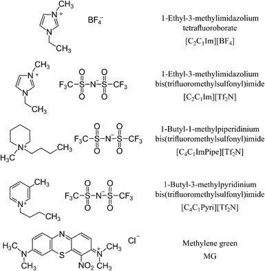
The present paper reports an exploratory study of processes induced by impact of low energy (0–30 eV) electrons with representative ionic liquids. A list of the compounds used in this study and their structures is given in Fig. 1. Electronically excited states are studied by EEL spectra and by quantum chemical calculations. EEL spectra were recorded at a number of electron energies, yielding information about the nature of the excitation process. Vibrational EEL spectra were recorded primarily to prove authenticity of the samples. The possibility of studying molecules embedded in the ionic liquid was explored by measuring a solution of methylene green in [C2C1Im][BF4].
2 Methods
2.1 Electron impact spectrometer
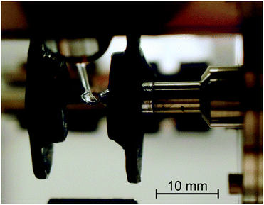
The measurements were performed using an electron-impact spectrometer which has been constructed initially to study gas phase molecules and has been described earlier.28,29 Schematic diagram of the instrument is given for example in ref. 30. It employs hemispherical analyzers to improve resolution, which was 0.02 eV at an electron beam current of 300 pA. For the purpose of the present study a droplet of an ionic liquid, suspended by a 2.5 mm diameter loop of molybdenum wire, was placed in the electron beam as shown in Fig. 2. Scattered electrons were collected at an angle of 135° with respect to the incident beam, that is, approximately at the specular angle with respect to the droplet surface. The droplet can be withdrawn from the collision region by means of a stepping motor to allow ‘tuning’ of the instrument on effusive helium beam emanating from a nozzle, as described in the gas-phase studies.28,29 The droplet is then returned to the original position for measurements of the ionic liquid. The droplet is periodically withdrawn and the quality of the electron beam and analyzer settings are verified on helium.The present instrument has been constructed for gas-phase studies where pumping speed (10![[thin space (1/6-em)]](https://www.rsc.org/images/entities/char_2009.gif) 000 L s−1) had priority over residual gas contamination and is pumped by diffusion pumps to a base pressure of 10−7 mbar. In view of the modest vacuum it is essential to verify that the observed bands are due to the ionic liquids and not to impurities such as water or pump oil adsorbed on the surface of the droplet. The evidence which we put forward is:
000 L s−1) had priority over residual gas contamination and is pumped by diffusion pumps to a base pressure of 10−7 mbar. In view of the modest vacuum it is essential to verify that the observed bands are due to the ionic liquids and not to impurities such as water or pump oil adsorbed on the surface of the droplet. The evidence which we put forward is:
• Our vibrational energy-loss spectra agree well with the published IR spectra of the ionic liquids as will be shown in Section 3.2 below, devoted to vibrational EEL spectra.
• No vibrational bands of water are found in the vibrational energy-loss spectra—see also Section 3.2.
• The energy-loss spectra are different for different ionic liquids as will be shown in Section 3.3 below.
• The energy-loss spectra do not vary with time, even over the longest period which we tested which is about a week.
A steady state equilibrium between adsorption and desorption is thus reached, where the adsorbed molecules do not measurably contribute to the spectra.
The energy scales were calibrated on helium to within ±0.01 eV when the droplet was withdrawn. The zero of the energy-loss scale was calibrated on the elastic peak, the energy of the incident electrons on the 19.365 eV 2S resonance in helium.31 The surface of the ionic liquid droplet is likely to have a potential different from the empty space which the electron beam feels when the droplet is removed. This should leave the energy-loss scale unchanged, and this expectation is confirmed since we observed that the elastic peak in the energy-loss spectra of the ionic liquid appeared at 0 ± 0.01 eV after the energy-loss scale was calibrated on helium. The incident and residual energy scales will, on the other hand, be shifted by the droplet surface potential and we do not have an independent way of calibrating it. We verified on helium, however, that our analyzer was capable of collecting electrons with energies down to about 0.020 eV, and assuming that this capacity persists when the droplet is moved into the beam, we calibrated the residual energy scale on the onset of the scattered electron current. This required a shift of the order of −0.3 eV (i.e., the droplet surface has a negative potential), which depends slightly on which ionic liquid is used, and this shift was applied where required. We assume that the energy-loss scale is accurate to within ±0.010 eV, the incident and residual energies scale to within ±0.3 eV.
The ionic liquids were purchased from Sigma-Aldrich with a stated purity of 97%. They were not further purified except for the intrinsic removal of water and other volatile impurities by the vacuum.
2.2 Experimental method
The spectrometer directs a beam of quasi-monoenergetic electrons with a variable incident energy Ei onto the sample, which is either the ionic liquid droplet or effusive helium gas beam for calibration. Scattered electrons are collected at an angle of 135° with respect to the incident beam and passed through an energy analyzer, where only electrons of a given residual energy Er pass to reach the detector, a channel electron multiplier. The electron energy loss is given as ΔE = Ei − Er. Various types of spectra can be recorded depending how are Ei and Er scanned.2.3 Theory
All geometries in this study were optimized at the dispersion-corrected33,34 hybrid density functional level of theory. The resolution of identity approximation was used throughout.35–37 We employed the PBE0 functional38,39 together with the spherical, atom-centered def2-TZVP basis set.40,41 This combined level of theory will be abbreviated as PBE0-D3(BJ)/TZ. These geometries were verified as minima by harmonic frequency calculations at the same level of theory. For the geometry optimizations and frequency calculations, the TURBOMOLE suite of programs42,43 was used (numerical integration grid m4). We performed calculations on the individual ions [C2C1Im]+, [C4C1Pipe]+, [C4C1Pyri]+, [BF4]−, and [Tf2N]−.Based on these geometries, single-point calculations employing the hybrid functional BHLYP44–46 were performed using TURBOMOLE. For this purpose, the def2-TZVP(-f) (i.e., Ahlrichs' def2-TZVP40,41 without f-functions) with four additional diffuse functions (2s2p) on each boron, nitrogen, and oxygen atom was used. We abbreviate this basis as mTZ. From this ground-state reference, singlet and triplet excitations were computed by the density functional multi-reference configuration interaction (DFT/MRCI) method.47 In the further context, we will simply refer to this approach as DFT/MRCI, implying that the underlying reference was obtained at the BHLYP/mTZ level. 20 singlet and triplet states were computed for each ion (10 for [Tf2N]−). Symmetry was exploited if possible. The DFT/MRCI method has been chosen instead of, e.g., TD-DFT, since it yields accurate singlet as well as triplet excitation energies within 0.2 eV.47–49 TD-DFT may perform well for singlet excitations but is unreliable in the description of triplet excitations.48,50 The reason why we used a different level for the geometry optimizations (i.e., PBE0-D3(BJ)/TZ) than for the excited state treatment is due to the fact that the DFT/MRCI method is only parametrized for the BHLYP functional and there are no analytic gradients for DFT/MRCI. The BHLYP functional by itself, however, is not a good choice for geometry optimizations, therefore we prefer the PBE0 functional for this. For the intensities of singlet excitations, the length form of the oscillator strengths is used. Computed UV/Vis spectra are obtained by broadening the singlet intensities with Gaussian shape functions using a full width at 1/e maximum of 0.4 eV. Triplet states are simply visualized as sticks with a fixed oscillator strength.
3 Results and discussion
3.1 Overview spectra
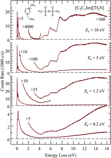
Fig. 3 shows EEL spectra of [C2C1Im][Tf2N] recorded at four different residual energies. At the lowest residual energy Er = 0.2eV the spectrum is largely continuous, both in the vibrational energy-loss region up to 4 eV, and in the electronic excitation/ionization region above 4.5 eV. The excitation of a quasi-continuum of high-lying overtones of low-frequency vibrations without selectivity for certain vibrational modes, followed by emission of a slow electron is reminiscent of the ‘unspecific’ excitation of large molecules, examples of which are given in ref. 51 and in earlier references given therein, and the theoretical description of which was presented by Gauyacq.52 The liquid thus behaves as a very large molecule and the quasi-continuum presumably consists of both intramolecular and intermolecular vibrations. The excitation of low-frequency modes is related to intramolecular vibrational redistribution (IVR) whereby the incoming electron is initially coupled to a single high vibration but fast IVR into a bath of low frequency vibrations occurs before the electron departs. Multiple scattering is also likely to contribute to high vibrational energy losses.The excitation of the quasi-continuum is progressively reduced with increasing residual energy and discrete features appear and become dominant at Er = 10 eV, both in the vibrational (ΔE < 4 eV) and the electronic (ΔE > 4 eV) excitation domains. The trend of decreasing continuum continues at the even higher residual energy of Er = 20 eV which is an advantage for observing discrete spectral features, but it does not improve by much, and it is at the price of decreasing count rate. An example of an EEL spectrum recorded with Er = 20 eV is given in the ESI.† The choice of Er = 10 eV is thus a meaningful compromise and means of selecting those electrons which have in their majority not undergone multiple collisions, and where spectroscopic data, governed by the Franck–Condon principle, can be gathered.
Multiple scattering limits the distance which the electrons can travel, as expressed by the inelastic mean-free-path (IMFP), and thus defines the surface specificity of the present study. The IMFP values in the literature are given mostly for much higher energies. It has been pointed out that calculations using the many-pole models, developed for these high energies, grossly overestimate the IMFP for electron energies below about 20 eV.53 The value most relevant to the present study appears to be that of Swiderek and co-workers (Hammann et al.26) who measured the vibrational energy-loss spectra of a self assembled monolayer of 11-mercaptoundecene under ammonia films of variable thickness, with electrons of 5.5 eV energy. They found that the 11-mercaptoundecene bands become very weak with more than 4 monolayers of ammonia, indicating an IMFP of 5–10 Å. Mean free path has also been derived from low energy electron transmission (LEET) experiments.25 As an example, the value of 8 Å was quoted for benzene at 15 K and for electrons in the 1–10 eV range.54
As another indicator, IMFP has been measured to be about 5 Å for an Fe film, nearly constant for electrons in the 4–18 eV range55 and about 3 Å for Cu.53 The IMFP is likely to be longer in the IL than in a metal, because of the possibility of many low-lying inelastic electronic excitations in the metal which are not possible in a wide band gap material like the IL, leading to an estimate compatible with the 5–10 Å based on the ammonia study.
The excitation functions, i.e., scattered signal for the elastic scattering and representative vibrational and electronic energy-losses were also recorded as a function of incident electron energy and examples are shown in the ESI.† Excitation functions in isolated molecules generally exhibit narrow features caused by resonances, but no narrow features were found in the ionic liquids. Energy-loss spectra were also recorded for higher energy-losses up to 50 eV. The spectra are continuous, without structure, and a representative example is shown in the ESI.†
3.2 Vibrational spectra
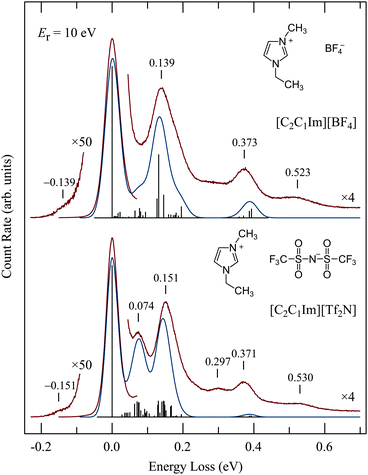
Representative vibrational spectra are shown in Fig. 4. The spectrum of [C2C1Im][Tf2N] is in an excellent agreement with the energy-loss spectrum recorded for the same IL with an incident electron energy of 20 eV at room temperature by Krischok et al.19 The spectra in Fig. 4 were recorded with the relatively high residual electron energy of 10 eV to reduce the contribution of multiple scattering as discussed above. Published56,57 infrared spectra are shown by vertical bars and also convoluted by Gaussian functions. Ref. 57 lists vibrational frequencies only down to 0.07 eV, for lower frequencies only those of the Tf2N anion were found58 and are therefore shown in Fig. 4; the cation frequencies below 0.07 eV are not shown.The agreement of the EEL and IR spectra is satisfactory. In particular the peak at 0.074 eV in the lower spectrum is missing in the upper spectrum, in agreement with the IR spectra. The normal mode analysis reveals that many of the vibrations in this energy range are due to the Tf2N anion. The band at 0.297 eV in the lower spectrum, and also the signal at about the same energy (without a pronounced band) in the upper spectrum, as well as the bands at 0.530 and 0.523 eV are likely due to overtone and combination vibrations, which are generally excited more strongly in EEL than in IR spectroscopies (0.297 eV ≅ 2 × 0.151 eV). For isolated molecules, overtone excitation is a manifestation of resonances, i.e., a residence time of the incoming electron longer than a normal passage time. The prominence of overtones thus indicates resonances, although they must be strongly lifetime broadened because they were not observed in the excitation functions as already mentioned above. Hot bands are observed on the left of the elastic peak.
The good agreement with IR spectra confirms that our EEL spectra are due, at least to a great majority, to the ionic liquids and not to adsorbed impurities. Note in particular that no water bands, which would be at 0.453 and 0.466 eV, can be discerned. Water is, according to a measurement with a residual gas analyzer, the major residual gas in our system.
3.3 Electronic excitation
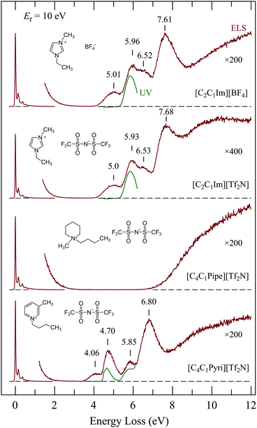
Fig. 5 shows the EEL spectra of four representative ionic liquids. UV absorption spectra which we recorded for dilute solutions of the ILs in spectroscopy grade methanol are shown under the EEL spectra for comparison. The UV spectrum of [C4C1Pipe][Tf2N] is not shown because it was essentially empty, with only very weak absorption presumably due to impurities. The interesting points are:• The spectra of [C2C1Im][BF4] and [C2C1Im][Tf2N] are nearly identical in the 4–8 eV range, although they differ in the 0–1 eV vibrational range as shown in Fig. 4. This indicates that the four bands in the 4–8 eV range are due to electronic excitation of the π-system of the imidazolium ring. There is a slight difference above 8 eV—the scattered current intensity is higher in [C2C1Im][Tf2N] than in [C2C1Im][BF4]. This extra intensity must thus be due to the [Tf2N]− anion.
• [C4C1Pipe][Tf2N] has a wide ‘empty’ energy-loss range between 2 and 7 eV, reflecting the absence of a π,π* system on the cation. This may make [C4C1Pipe][Tf2N] a suitable host for electron-collision studies of embedded compounds as discussed below.
• The discrete bands in the 3.5–8 eV range of [C4C1Pyri][Tf2N] differ clearly from those of [C2C1Im][Tf2N] and [C2C1Im][BF4], further confirming that these bands are due to the π,π* system of the cation.
• The lowest EEL bands of the three ILs with a π system on the cation have no counterparts in the corresponding UV absorption spectra. This identifies the lowest EEL bands as due to spin-forbidden transitions, i.e., to triplet states localized on the cation.
Revealing is the comparison of the [C2C1Im][Tf2N] spectrum in Fig. 5 with the EEL spectrum of the same compound recorded with 60 keV incident electron energy in a TEM by Miyata et al.22 They observed bands at 6 and 7.6 eV which agree well with our 5.93 and 7.68 eV bands, but they did not see the 5.0 eV. This is a consequence of the different conditions of measurement. They measured in forward direction, i.e., electrons which traversed a liquid drop placed on a carbon mesh grid, and the EELS spectra were taken from a relatively thin area, which was estimated to be ∼2–20 nm thick. The selection rules for EEL spectroscopy in the limit of forward scattering and large electron energies converge to the limit of dipole selection rules.32 The conditions of Miyata et al. essentially reached this limit and their observation is consequently limited to dipole-allowed transitions, i.e., to the equivalent of the UV absorption spectrum. Our measurement was performed with much slower electrons (∼15 eV in Fig. 5) and in the backward direction. Dipole and/or spin forbidden transitions can be observed under our conditions.
3.4 Comparison with theory
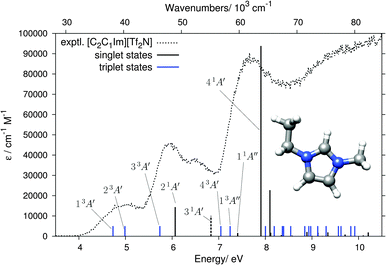
The absence of anion-related features in the 4–8 eV range allows us to calculate the cations and anions separately. We computed 20 singlet and 20 triplet states (10 within A′ and A′′ each) of the Cs symmetric [C2C1Im]+ cation by DFT/MRCI and the results are listed in Table 1 and shown in Fig. 6. The lowest computed singlet state with non-negligible oscillator strength is the 21A′ state at 6.07 eV. The experimental EEL bands of [C2C1Im][BF4] and [C2C1Im][Tf2N] at 5.96 and 5.93 eV, respectively, are thus identified as singlet ππ* transitions to the 21A′ state. Additionally, the slightly lower-lying triplet state 33A′ is very likely contributing to the signal intensities on the low energy flanks of the 5.94 and 5.96 eV experimental EEL bands. Our computation further permits the assignment of the 5 eV band in the EEL spectra of [C2C1Im][BF4] and [C2C1Im][Tf2N] to the 13A′ and 23A′ triplet states, calculated just below 5 eV and both originating from excitations within the π orbitals.| Singlet states | Triplet states | |||
|---|---|---|---|---|
| State | VEE (eV) | f L | State | VEE (eV) |
| 21A′ | 6.07 | 0.1437 | 13A′ | 4.73 |
| 31A′ | 6.83 | 0.0004 | 23A′ | 4.99 |
| 11A′′ | 7.41 | 0.0160 | 33A′ | 5.74 |
| 41A′ | 7.91 | 0.9381 | 43A′ | 7.05 |
| 51A′ | 8.10 | 0.2270 | 13A′′ | 7.24 |
| 21A′′ | 8.12 | 0.0171 | 23A′′ | 8.00 |
| 31A′′ | 8.34 | 0.0047 | 33A′′ | 8.19 |
| 41A′′ | 8.49 | 0.0007 | 43A′′ | 8.36 |
| 51A′′ | 8.58 | 0.0030 | 53A′′ | 8.39 |
| 61A′ | 8.89 | 0.0212 | 53A′ | 8.55 |
| 61A′′ | 9.01 | 0.0016 | 63A′′ | 8.85 |
| 71A′′ | 9.07 | 0.0005 | 73A′′ | 8.93 |
| 81A′′ | 9.13 | 0.0172 | 63A′ | 8.93 |
| 91A′′ | 9.22 | 0.0020 | 83A′′ | 8.97 |
| 71A′ | 9.34 | 0.0191 | 93A′′ | 9.12 |
| 101A′′ | 9.43 | 0.0002 | 103A′′ | 9.30 |
| 81A′ | 9.71 | 0.0085 | 73A′ | 9.57 |
| 91A′ | 9.83 | 0.0248 | 83A′ | 9.62 |
| 101A′ | 10.10 | 0.0040 | 93A′ | 9.83 |
| 111A′ | 10.21 | 0.0189 | 103A′ | 9.92 |
The experimental EEL band at around 6.5 eV in both [C2C1Im][BF4] and [C2C1Im][Tf2N] could be assigned as the singlet ππ* state (31A′). The oscillator strength of this transition is very low and it therefore does not appear as a visible black stick in Fig. 6 (it is marked by a dashed stick), but it can appear in the EEL spectrum because electronic excitations by electron impact are not limited by dipole selection rules. The most intense band in the EEL spectrum is at 7.6–7.7 eV. DFT/MRCI calculations identify the 41A′ state (π → π*) to be at the origin of this band. Its computed energy of 7.91 eV is within the typical error range of the DFT/MRCI method (≈0.2 eV). Additionally, the low-energy side of the experimental band is enhanced by the lower lying 11A′′ singlet and 13A′′ triplet πσ* states.
A remark should be made about the recent calculation17 on the [C2C1Im][Tf2N] ion pair which, using the B3LYP59,60 method, yielded a charge-transfer (CT) state around 5.0 eV which was proposed as an interpretation of a very weak 260 nm (4.77 eV) UV absorption band (about 2000× weaker than the 210 nm band), reported in the same publication. Our 5.0 eV EEL band cannot be assigned to this CT state because it is at the same energy for two different anions with different gas phase vertical detachment energies (VDE), namely 7.34 eV,61 for BF4− and 6.74 eV15 for [Tf2N]−. In fact, we note that the calculated CT state of ref. 17 should be taken with caution because such CT states tend to appear as artifacts due to the low amount of Fock exchange in B3LYP. More details on the problems linked to the study of CT states with semi-local density functionals can be found in ref. 62. A range-separated functional or hybrids with about 50% Fock exchange are necessary to properly describe CT states in such systems.63
We have also computed the 10 lowest singlet and triplet states of the [C2C1Im][BF4] ion pair for comparison (see Fig. S6 and Table S1 in the ESI†). The position of all states below 8 eV is hardly affected by the presence of the anion and the induced shifts are smaller than the intrinsic accuracy of the DFT/MRCI method. Thus, for the excited states <8 eV, we consider it reasonable to restrict the study to the separated cations. There are small changes which slightly improve the agreement with the experiment, however. The most intense peak, at 7.91 eV for the isolated cation, shifts to 7.71 eV in the ion pair. Although this change is within the intrinsic accuracy of the DFT/MRCI method, it improves the agreement with the experiment (Fig. S7 in the ESI†). The counter anion further slightly increases the oscillator strength and decreases the energy of the nearly forbidden 31A′ transition at 6.8 eV, shown as a dashed stick in Fig. 6, further improving the agreement with the experiment.
Fig. 7 compares theory and experiment for the second aromatic cation of this study, [C4C1Pyri]+. The computed states are listed in Table 2. Similarly to the [C2C1Im]+ case, the lowest EEL band at 4.06 eV, without a counterpart in the UV spectrum (Fig. 5), can be assigned to the two ππ* triplet states 13A and 23A. The 4.70 and 5.85 eV EELS bands, with counterparts in the UV spectrum (Fig. 5), can be assigned to the ππ* transitions 21A and 31A, respectively. The triplet states 33A and 43A are located just below these two singlet bands and are likely to contribute to the signal intensities of the EEL spectrum. Several singlet and triplet states contribute to the most intense band in the EEL spectrum at 6.80 eV. The main contributor, also in best agreement with the experimental EEL maximum in terms of energy, is the 51A π → π* state. There is no noticable effect of different orientations of the butyl chain in [C4C1Pyri]+ on the excitation pattern in the energy range <8 eV (see Fig. S7 in the ESI†).
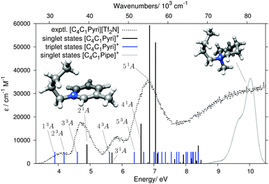 | ||
| Fig. 7 Results of the DFT/MRCI calculation for the [C4C1Pyri]+ cation, shown in the same format as in Fig. 6. The grey dotted line on the right shows the calculated singlet states of the [C4C1Pipe]+ cation. | ||
| Singlet states | Triplet states | |||
|---|---|---|---|---|
| State | VEE (eV) | f L | State | VEE (eV) |
| 21A | 4.90 | 0.0819 | 13A | 3.89 |
| 31A | 5.69 | 0.0471 | 23A | 4.18 |
| 41A | 6.60 | 0.1708 | 33A | 4.60 |
| 51A | 6.82 | 0.0054 | 43A | 5.61 |
| 61A | 6.86 | 0.5928 | 53A | 6.38 |
| 71A | 7.05 | 0.5188 | 63A | 6.68 |
| 81A | 7.11 | 0.0431 | 73A | 7.01 |
| 91A | 7.30 | 0.0016 | 83A | 7.13 |
| 101A | 7.43 | 0.0022 | 93A | 7.25 |
| 111A | 7.65 | 0.0188 | 103A | 7.36 |
| 121A | 7.82 | 0.0052 | 113A | 7.55 |
| 131A | 7.92 | 0.0060 | 123A | 7.72 |
| 141A | 7.93 | 0.0384 | 133A | 7.78 |
| 151A | 8.18 | 0.0228 | 143A | 8.01 |
| 161A | 8.21 | 0.0080 | 153A | 8.05 |
| 171A | 8.32 | 0.0137 | 163A | 8.16 |
| 181A | 8.34 | 0.0117 | 173A | 8.21 |
| 191A | 8.39 | 0.0770 | 183A | 8.24 |
| 201A | 8.47 | 0.0028 | 193A | 8.31 |
| 211A | 8.48 | 0.0154 | 203A | 8.39 |
The Gaussian-broadended singlet states of the saturated [C4C1Pipe]+ cation are also plotted in Fig. 7. No bands are calculated below ≈8 eV, thus rationalizing the wide ‘empty’ range in the experimental EEL spectrum in Fig. 5.
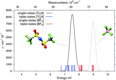
The measured EEL signal of [C4C1Pipe][Tf2N] at and beyond 7 eV coincides with excitations in the [Tf2N]− anion, the computed singlet and triplet states of which are, together with those of [BF4]− anion, shown in Fig. 8. For both anions the excitations are at energies higher than those of the aromatic cations [C2C1Im]+ and [C4C1Pyri]+. The order is reversed in the case of the saturated [C4C1Pipe]+ cation, however, where the lowest states of the [Tf2N]− anion lie below those of the cation. The signal close to 7 eV in the EEL of [C4C1Pipe][Tf2N] in Fig. 5 is therefore due to excitations in the [Tf2N]− anion.
3.5 Imbedded compounds
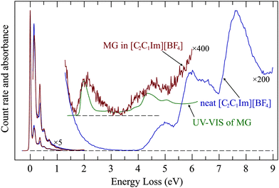
The above results show that ionic liquids could serve as a host for electron-impact studies of nonvolatile compounds. As a proof of principle we present in Fig. 9 the spectrum of a saturated (about 1 mol L−1) solution of methylene green in [C2C1Im][BF4]. The presence of methylene green clearly gives rise to a new band the energy of which coincides with that of the methylene green UV absorption.The EEL band has an onset which coincides with that of the UV band but is nearly twice as broad on the high energy side. This is presumably due to simultaneous excitation of vibrations, either by non-Franck–Condon excitation due to relaxation during the time of presence of the incoming electron, or by multiple collisions.
The methylene green EEL band at 2 eV becomes weaker during the measurements and nearly disappears after around 1 hour, indicating that it is bleached by the incoming electrons whose energy is sweeping in the 10–15 eV range. This is remarkable, because with our current of only about 200 pA, focused to a spot of 0.25 mm diameter, the dose during this time span is only about 200 electrons per nm2. The droplet which we recovered after the EEL measurements had an unchanged UV spectrum, indicating that the bulk of the solution remained unchanged. The bleaching thus occurs only on the surface, is very efficient, and the bleached molecules remain on the surface, they are not replenished from the bulk. An attempt to make use of the wider ‘empty’ spectral range of [C4C1Pipe][Tf2N] to record a wider EEL spectrum of methylene green failed. Although the concentration of the solution of methylene green in [C4C1Pipe][Tf2N] was also about 1 mol L−1 and was optically equally dark as that in [C2C1Im][BF4], no methylene green band appeared in the EEL spectrum (Fig. S5 in the ESI†). In view of the surface specificity within about 1 nm the most probable explanation is that the depth profile of methylene green concentration is very different in the two solvents, with methylene green exposed to the incoming electrons in [C2C1Im][BF4] but hidden in [C4C1Pipe][Tf2N].
This experimental results can be discussed in relation to the existing knowledge in the gas–IL surface structure.23 Various studies indicate that the alkyl chain orientation at the outer surface is upright and that they form, together with the CF3 groups if [Tf2N]− is present, an ionophobic layer.23,64 The orientation of the alkyl chains depends on their length and on the nature (size) of the anions. The packing density of alkyl chains is lower than a full monolayer, however. Methylene green is a salt, the chromophore is a cation and is likely to be found in the “ionic underlayer” or the bulk of the IL, below the alkyl chains and CF3 groups. The longer alkyl groups in and presence of CF3 groups in [C4C1Pipe][Tf2N] as compared to [C2C1Im][BF4] could make the ionophobic layer thicker and denser, providing a shielding of the Methylene green chromophore from the incoming electrons. Methylene green is a salt and the question of ion association must therefore be posed. Lui et al.65 have shown that ionic liquids are “super-dissociating” solvents because they completely divorce the solute cations and anions from each other. That implies that our EEL band is that of methylene green cation solvated by [BF4]− anions. The methylene green transition is local on the cation, little affected by the anion (unlike the charge-transfer transition of Kosower's salt used by Lui et al.), and our experiment does not, unfortunately, provide indication on the nature of the anion.
4 Conclusions
This paper reports an exploratory study of extending low-energy (0–30 eV) electron-impact studies, as they have been widely applied to gas phase molecules, to ionic liquids. Two groups of scattered electrons were found. There is an intense group of low energy electrons which have excited mostly a structureless quasi-continuum of high overtones and combination vibrations of low-frequency modes. This behavior resembles a similar effect (unspecific vibrational excitation) in molecules, where it becomes more pronounced with increasing size of the molecule. The ionic liquid thus behaves like a very large molecule in this respect. This quasi-continuum becomes weak for electrons scattered with higher energies, 10–20 eV, and discrete vibrational and electronic losses become dominant. The elastic peak appears 0.04 eV wide in the spectrum, wider than the experimental resolution of 0.02 eV, indicating that the elastic and vibrational energy-loss bands are broadened by simultaneous or consecutive excitations of low-energy, presumably in part interionic, vibrations. The vibrational energy-loss spectra are compatible with the known infrared spectra. The excitation functions (recording the elastic, or vibrationally or electronically inelastic peaks as a function of the incident electron energy) have not revealed any structure which would be due to negative ion resonances, ubiquitous for free molecules. But prominent excitation of vibrational overtones does indicate resonant excitation mechanism in addition to the dipole mechanism.Electronically excited states for four ionic liquids were characterized by energy-loss spectra and DFT/MRCI calculations, with good agreement, permitting the assignment of the observed bands. It is shown that the spectra of the ionic liquids where the cations have π and π* orbitals are dominated by (π,π*) transitions of the cations up to about 8 eV. The lowest energy loss bands were assigned to triplet states. The spectrum is essentially empty up to about 7 eV for the saturated piperidinium based ionic liquid [C4C1Pipe][Tf2N]. The signal at 7 eV and above in this ionic liquid is assigned to transitions of the [Tf2N]− anion.
Spectrum of methylene green dissolved in [C2C1Im][BF4] was observed, demonstrating that ionic liquids may serve as hosts for nonvolatile compounds, thus extending the range of applicability of low energy electron spectroscopic techniques. The methylene green energy-loss band is slightly broadened to higher energies compared to a UV spectrum, presumably by co-excitation of vibrations of the liquid, but the onset of the band in not noticeably shifted. The methylene green band was bleached by a surprisingly low dose of 10–20 eV electrons and the bleached methylene green was not replenished from the bulk. The absence of the methylene green band in the energy-loss spectrum of a solution where [C2C1Im][BF4] was replaced by [C4C1Pipe][Tf2N] indicates that it is displaced from the surface in this case.
This exploratory effort indicates that a wide range of phenomena may potentially be studied by this technique, going beyond the detection of spin-forbidden and energetically high-lying electronic transitions which are the focus of the present work. To name a few, the surface specificity and capacity to distinguish between ionic liquids and ionic solutes (even though high concentration is required) allow study of surface distribution of solutes. Study of electron-driven chemistry in ionic liquids, similar to the studies in solids,26 and possibly using focused electron beams66 to create nanostructures, is likely to be interesting. The electronic excitation studied here is, together with dissociative electron attachment, an important intermediate of the electron-driven chemistry.
Acknowledgements
This research is part of project No. 200020-144367/1 of the Swiss National Science Foundation and of the COST Action CM1301 CELINA. C.B. and S.G. are grateful for support by the Fonds der Chemischen Industrie and the DFG in the framework of the SFB 813 (‘Chemistry at Spin-Centers’).References
- E. W. Castner Jr., C. J. Margulis, M. Maroncelli and J. F. Wishart, Annu. Rev. Phys. Chem., 2011, 62, 85–105 CrossRef PubMed.
- F. Endres and S. Z. E. Abedin, Phys. Chem. Chem. Phys., 2006, 8, 2101 RSC.
- A. Varzi, A. Balducci and S. Passerini, J. Electrochem. Soc., 2014, 161, A368 CrossRef CAS PubMed.
- G. P. S. Lu, H. N. Tsao, S. M. Zakeeruddin, M. Grätzel and P. J. Dyson, ACS Appl. Mater. Interfaces, 2014, 6, 13571–13577 Search PubMed.
- B. Qiu, B. Lin and F. Yan, Polym. Int., 2013, 62, 35–337 CrossRef PubMed.
- Y.-H. Chiu, B. L. Austin, R. A. Dressler, D. Levandier, P. T. Murray, P. Lozano and M. Martinez-Sánchez, J. Propul. Power, 2005, 21, 416 CrossRef CAS.
- Y.-H. Chiu, G. Gaeta, D. Levandier, R. A. Dressler and J. Boatz, Int. J. Mass Spectrom., 2007, 265, 146 CrossRef CAS PubMed.
- M. Brettholle, O. Höfft, L. Klarhöfer, S. Mathes, W. Maus-Friedrichs, S. Z. E. Abedin, S. Krischok, J. Janek and F. Endres, Phys. Chem. Chem. Phys., 2010, 12, 1750 RSC.
- I. A. Shkrob, T. W. Marin, S. D. Chemerisov and J. F. Wishart, J. Phys. Chem. B, 2011, 115, 3872 CrossRef CAS PubMed.
- J. F. Wishart, Ionic Liquids further UnCOILed: Critical Expert Overviews, Wiley, Ltd, Chichester, 2014, vol. 1, pp. 259–274 Search PubMed.
- K. R. J. Lovelock, I. J. Villar-Garcia, F. Maier, H.-P. Steinrück and P. Licence, Chem. Rev., 2010, 110, 5158–5190 CrossRef CAS PubMed.
- D. Strasser, F. Goulay, M. S. Kelkar, E. J. Maginn and S. R. Leone, J. Phys. Chem. A, 2007, 111, 3191 CrossRef CAS PubMed.
- D. Yoshimura, T. Yokoyama, T. Nishi, H. Ishii, R. Ozawae, H. Hamaguchi and K. Seki, J. Electron Spectrosc. Relat. Phenom., 2005, 144–147, 319 CrossRef CAS PubMed.
- O. Höfft, S. Bahr, M. Himmerlich, S. Krischok, J. A. Schaefer and V. Kempter, Langmuir, 2006, 22, 7120 CrossRef PubMed.
- L. Sistík, M. Oncák and P. Slavícek, Phys. Chem. Chem. Phys., 2011, 13, 11998 RSC.
- T. Ogura, N. Akai, A. Kawai and K. Shibuya, Chem. Phys. Lett., 2013, 555, 110–114 CrossRef CAS PubMed.
- S. Vyas, C. Dreyer, J. Slingsby, D. Bicknase, J. M. Porter and C. M. Maupin, J. Phys. Chem. A, 2014, 118, 6873–6882 CrossRef CAS PubMed.
- R. Cooper, A. M. Zolot, J. A. Boatz, D. P. Sporleder and J. A. Stearns, J. Phys. Chem. A, 2013, 117, 12419–12428 CrossRef CAS PubMed.
- S. Krischok, M. Eremtchenko, M. Himmerlich, P. Lorenz, J. Uhlig, A. Neumann, R. öttking, W. J. D. Beenken, O. Höfft, S. Bahr, V. Kempter and J. A. Schaefer, J. Phys. Chem. B, 2007, 111, 4801 CrossRef CAS PubMed.
- C. M. Wang, W. Xu, J. Liu, D. W. Choi, B. Arey, L. V. Saraf, J. G. Zhang, Z. G. Yang, S. Thevuthasan, D. R. Baer and N. Salmon, J. Mater. Res., 2015, 25, 17018–17023 Search PubMed.
- A. C. Lang, J. D. Sloppy, H. Ghassemi, R. C. Devlin, R. J. Sichel-Tissot, J.-C. Idrobo, S. J. May and M. L. Taheri, ACS Appl. Mater. Interfaces, 2014, 6, 35–337 Search PubMed.
- T. Miyata, M. Fukuyama, A. Hibara, E. Okunishi, M. Mukai and T. Mizoguchi, Microscopy, 2014, 63, 377–382 CrossRef PubMed.
- K. R. J. Lovelock, Phys. Chem. Chem. Phys., 2012, 14, 5071–5089 RSC.
- C. S. Santos and S. Baldelli, Chem. Soc. Rev., 2010, 39, 2136–2145 RSC.
- R. Naaman and L. Sanche, Chem. Rev., 2007, 107, 1553–1579 CrossRef CAS PubMed.
- T. Hamann, L. Kankate, E. Böhler, J. H. Bredehöft, F. M. Zhang, A. Gölzhäuser and P. Swiderek, Langmuir, 2012, 28, 367–376 CrossRef CAS PubMed.
- M. Bazin, M. Michaud and L. Sanche, J. Chem. Phys., 2010, 133, 155104 CrossRef CAS PubMed.
- M. Allan, J. Phys. B: At., Mol. Opt. Phys., 2007, 40, 3531–3544 CrossRef CAS.
- M. Allan, Phys. Rev. A: At., Mol., Opt. Phys., 2010, 81, 042706 CrossRef.
- H. Hotop, M.-W. Ruf, M. Allan and I. I. Fabrikant, Adv. At., Mol., Opt. Phys., 2003, 49, 85 CAS.
- A. Gopalan, J. Bömmels, S. Götte, A. Landwehr, K. Franz, M. W. Ruf, H. Hotop and K. Bartschat, Eur. Phys. J. D, 2003, 22, 17 CrossRef CAS.
- E. N. Lassettre and S. A. Francis, J. Chem. Phys., 1964, 40, 1208 CrossRef CAS PubMed.
- S. Grimme, J. Antony, S. Ehrlich and H. Krieg, J. Chem. Phys., 2010, 132, 154104 CrossRef PubMed.
- S. Grimme, S. Ehrlich and L. Goerigk, J. Comput. Chem., 2011, 32, 1456–1465 CrossRef CAS PubMed.
- O. Vahtras, J. Almlöf and M. W. Feyereisen, Chem. Phys. Lett., 1993, 213, 514–518 CrossRef CAS.
- K. Eichkorn, F. Weigend, O. Treutler and R. Ahlrichs, Theor. Chem. Acc., 1997, 97, 119–124 CrossRef CAS.
- F. Weigend, Phys. Chem. Chem. Phys., 2006, 8, 1057–1065 RSC.
- J. P. Perdew, K. Burke and M. Ernzerhof, Phys. Rev. Lett., 1996, 77, 3865–3868 CrossRef CAS.
- C. Adamo and V. Barone, J. Chem. Phys., 1999, 110, 6158–6170 CrossRef CAS PubMed.
- A. Schäfer, C. Huber and R. Ahlrichs, J. Chem. Phys., 1994, 100, 5829–5835 CrossRef PubMed.
- F. Weigend and R. Ahlrichs, Phys. Chem. Chem. Phys., 2005, 7, 3297–3305 RSC.
- R. Ahlrichs, M. Bär, M. Häser, H. Horn and C. Kölmel, Chem. Phys. Lett., 1989, 162, 165–169 CrossRef CAS.
- TURBOMOLE V6.5 2013, a development of University of Karlsruhe and Forschungszentrum Karlsruhe GmbH, 1989–2007, TURBOMOLE GmbH, since 2007; available from http://www.turbomole.com.
- A. D. Becke, Phys. Rev. A: At., Mol., Opt. Phys., 1988, 38, 3098–3100 CrossRef CAS.
- C. Lee, W. Yang and R. G. Parr, Phys. Rev. B: Condens. Matter Mater. Phys., 1988, 37, 785–789 CrossRef CAS.
- A. D. Becke, J. Chem. Phys., 1993, 98, 1372–1377 CrossRef CAS PubMed.
- S. Grimme and M. Waletzke, J. Chem. Phys., 1999, 111, 5645–5655 CrossRef CAS PubMed.
- M. R. Silva-Junior, M. Schreiber, S. P. A. Sauer and W. Thiel, J. Chem. Phys., 2008, 129, 104103 CrossRef PubMed.
- C. M. Marian and N. Gilka, J. Chem. Theory Comput., 2008, 4, 1501–1515 CrossRef CAS.
- M. J. G. Peach, M. J. Williamson and D. J. Tozer, J. Chem. Theory Comput., 2011, 7, 3578–3585 CrossRef CAS.
- M. Allan, J. Electron Spectrosc. Relat. Phenom., 1989, 48, 219 CrossRef CAS.
- J. P. Gauyacq, J. Phys. B: At., Mol. Opt. Phys., 1990, 23, 3041 CrossRef CAS.
- J. D. Bourke and C. T. Chantler, J. Phys. Chem. A, 2012, 116, 3202 CrossRef CAS PubMed.
- T. Goulet and J.-P. Jay-Gerin, Radiat. Phys. Chem., 1986, 27, 229–239 CrossRef CAS.
- R. Zdyb, T. O. Mentes, A. Locatelli, M. A. Niño and E. Bauer, Phys. Rev. B: Condens. Matter Mater. Phys., 2013, 87, 075436 CrossRef.
- N. E. Heimer, R. E. D. Sesto, Z. Meng, J. S. Wilkes and W. R. Carper, J. Mol. Liq., 2006, 124, 84–95 CrossRef CAS PubMed.
- J. Kiefer, J. Fries and A. Leipertz, Appl. Spectrosc., 2007, 61, 1306 CrossRef CAS PubMed.
- I. Rey, P. Johansson, J. Lindgren, J. C. Lasségues, J. Grondin and L. Servant, J. Phys. Chem. A, 1998, 102, 3249 CrossRef CAS.
- A. D. Becke, J. Chem. Phys., 1993, 98, 5648–5652 CrossRef CAS PubMed.
- P. J. Stephens, F. J. Devlin, C. F. Chabalowski and M. J. Frisch, J. Phys. Chem., 1994, 98, 11623–11627 CrossRef CAS.
- S. Giri, S. Behera and P. Jena, J. Phys. Chem. A, 2014, 118, 638–645 CrossRef CAS PubMed.
- A. Dreuw, J. L. Weisman and M. Head-Gordon, J. Chem. Phys., 2003, 119, 2943–2946 CrossRef CAS PubMed.
- S. Grimme, W. Hujo and B. Kirchner, Phys. Chem. Chem. Phys., 2012, 14, 4875–4883 RSC.
- K. Nakajima, A. Ohno, H. Hashimoto, M. Suzuki and K. Kimura, J. Chem. Phys., 2010, 133, 044702 CrossRef PubMed.
- M. Y. Lui, L. Crowhurst, J. P. Hallett, P. A. Hunt, H. Niedermeyer and T. Welton, Chem. Sci., 2011, 2, 1491–1496 RSC.
- I. Utke, P. Hoffmann and J. Melngailis, J. Vac. Sci. Technol., B: Microelectron. Nanometer Struct., 2008, 26, 1197 CAS.
Footnote |
| † Electronic supplementary information (ESI) available. See DOI: 10.1039/c5cp01417d |
| This journal is © the Owner Societies 2015 |

