 Open Access Article
Creative Commons Attribution 3.0 Unported Licence
Real-space grids and the Octopus code as tools for the development of new simulation approaches for electronic systems
Xavier
Andrade
*ab,
David
Strubbe
c,
Umberto
De Giovannini
d,
Ask Hjorth
Larsen
d,
Micael J. T.
Oliveira
e,
Joseba
Alberdi-Rodriguez
df,
Alejandro
Varas
d,
Iris
Theophilou
g,
Nicole
Helbig
g,
Matthieu J.
Verstraete
 e,
Lorenzo
Stella
h,
Fernando
Nogueira
i,
Alán
Aspuru-Guzik
b,
Alberto
Castro
 jk,
Miguel A. L.
Marques
 l and
Angel
Rubio
dm
aLawrence Livermore National Laboratory, Livermore, CA 94550, USA. E-mail: xavier@tddft.org
bDepartment of Chemistry and Chemical Biology, Harvard University, 12 Oxford Street, Cambridge, MA 02138, USA
cDepartment of Materials Science and Engineering, Massachusetts Institute of Technology, Cambridge, Massachusetts 02139, USA
dNano-Bio Spectroscopy Group and European Theoretical Spectroscopy Facility (ETSF), Universidad del País Vasco CFM CSIC-UPV/EHU-MPC & DIPC, 20018 Donostia-San Sebastián, Spain
eUnité Nanomat, Département de Physique, Université de Liège, Allée du 6 Août 17, B-4000 Liège, Belgium
fDept. of Computer Architecture and Technology, University of the Basque Country UPV/EHU, M. Lardizabal, 1, 20018 Donostia-San Sebastian, Spain
gPeter-Grünberg Institut and Institute for Advanced Simulation, Forschungszentrum Jülich, D-52425 Jülich, Germany
hAtomistic Simulation Centre, School of Mathematics and Physics, Queen's University Belfast, University Road, Belfast BT7 1NN, Northern Ireland, UK
iCenter for Computational Physics, University of Coimbra, Rua Larga, 3004-516 Coimbra, Portugal
jInstitute for Biocomputation and Physics of Complex Systems (BIFI) and Zaragoza Center for Advanced Modeling (ZCAM), University of Zaragoza, E-50009 Zaragoza, Spain
kARAID Foundation, María de Luna 11, Edificio CEEI Aragón, Zaragoza E-50018, Spain
lInstitut für Physik, Martin-Luther-Universität Halle-Wittenberg, Von-Seckendorff-Platz 1, 06120 Halle (Saale), Germany
mMax Planck Institute for the Structure and Dynamics of Matter, Hamburg, Germany
First published on 20th February 2015
Abstract
Real-space grids are a powerful alternative for the simulation of electronic systems. One of the main advantages of the approach is the flexibility and simplicity of working directly in real space where the different fields are discretized on a grid, combined with competitive numerical performance and great potential for parallelization. These properties constitute a great advantage at the time of implementing and testing new physical models. Based on our experience with the Octopus code, in this article we discuss how the real-space approach has allowed for the recent development of new ideas for the simulation of electronic systems. Among these applications are approaches to calculate response properties, modeling of photoemission, optimal control of quantum systems, simulation of plasmonic systems, and the exact solution of the Schrödinger equation for low-dimensionality systems.
1 Introduction
The development of theoretical methods for the simulation of electronic systems is an active area of study. This interest has been fueled by the success of theoretical tools like density functional theory (DFT)1,2 that can predict many properties with good accuracy at a relatively modest computational cost. On the other hand, these same tools are not good enough for many applications,3 and more accurate and more efficient methods are required.Current research in the area covers a broad range of aspects of electronic structure simulations: the development of novel theoretical frameworks, new or improved methods to calculate properties within existing theories, or even more efficient and scalable algorithms. In most cases, this theoretical work requires the development of test implementations to assess the properties and predictive power of the new methods.
The development of methods for the simulations of electrons requires continual feedback and iteration between theory and results from implementation, so the translation to code of new theory needs to be easy to implement and to modify. This is a factor that is usually not considered when comparing the broad range of methods and codes used by chemists, physicists and material scientists.
The most popular representations for electronic structure rely on basis sets that usually have a certain physical connection to the system being simulated. In chemistry, the method of choice is to use atomic orbitals as a basis to describe the orbitals of a molecule. When these atomic orbitals are expanded in Gaussian functions, it leads to an efficient method as many integrals can be calculated from analytic formulae.4 In condensed-matter physics, the traditional basis is a set of plane waves, which correspond to the eigenstates of a homogeneous electron gas. These physics-inspired basis sets have, however, some limitations. For example, it is not trivial to simulate crystalline systems using atomic orbitals,5 and, on the other hand, in plane-wave approaches finite systems must be approximated as periodic systems using a super-cell approach.
Several alternatives to atomic-orbital and plane-wave basis sets exist.6–10 One particular approach that does not depend on a basis set uses a grid to directly represent fields in real-space. The method was pioneered by Becke,11 who used a combination of radial grids centered around each atom. In 1994 Chelikowsky, Troullier and Saad12 presented a practical approach for the solution of the Kohn–Sham (KS) equations using uniform grids combined with pseudo-potentials. What made the approach competitive was the use of high-order finite differences to control the error of the Laplacian without requiring very dense meshes. From that moment, several real-space implementations have been presented.13–33
Discretizing in real-space grids does not benefit from a direct physical connection to the system being simulated. However, the method has other advantages. In first place, a real-space discretization is, in most cases, straight-forward to perform starting from the continuum description of the electronic problem. Operations like integration are directly translated into sums over the grid and differential operators can be discretized using finite differences. In fact, most electronic structure codes must rely on an auxiliary real-space discretization used, for example, for the calculation of the exchange and correlation (xc) term of DFT.
Grids are flexible enough to directly simulate different kinds of systems: finite, and fully or partially periodic. It is also possible to perform simulations with reduced (or increased) dimensionality. Additionally, the discretization error can be systematically and continuously controlled by adjusting the spacing between mesh points, and the physical extension of the grid.
The simple discretization and flexibility of the real space grids makes them an ideal framework to implement, develop and test new ideas. Modern electronic structure codes are quite complex, which means that researchers seldom can write a standalone code from scratch, but instead need to resort to existing codes to implement their developments.
From the many codes available, in our experience the real-space code Octopus22,34 provides an ideal framework for theory-development work. To illustrate this point, in this article we will explore some recent advances that have been made in computational electronic structure and that have been developed using the Octopus code as a base. We will pay special attention to the most unusual capabilities of the code, and in particular to the ones that have not been described in previous articles.22,34,35
2 The Octopus code
Octopus was started around 2000 in the group of professor Angel Rubio who, at that moment, was at the University of Valladolid, Spain. The first article using Octopus was published in 2001.36 Today, the code has grown to 200![[thin space (1/6-em)]](https://www.rsc.org/images/entities/char_2009.gif) 000 lines of code. Octopus receives contributions from many developers from several countries and its results have been used for hundreds of scientific publications.
000 lines of code. Octopus receives contributions from many developers from several countries and its results have been used for hundreds of scientific publications.
The original purpose of Octopus was to perform real-time time-dependent density functional theory (TDDFT) calculations, a method that had been recently proposed at the time for the calculation of excited-state properties in molecules.37 Beyond this original feature, over the time the code has become able to perform many types of calculations of ground-state and excited-state properties. These include most of the standard features of a modern electronic-structure package and some not-so-common capabilities.
Among the current capabilities of Octopus are an efficient real-time TDDFT implementation for both finite and periodic systems.38,39 Some of the research presented in this article is based on that feature, such as the simulation of photoemission, quantum optimal control, and plasmonic systems. The code can also perform molecular-dynamics simulations in the Born–Oppenheimer and Ehrenfest approximations. It also implements a modified Ehrenfest approach for adiabatic molecular dynamics40,41 that has favorable scaling for large systems. Octopus can perform linear-response TDDFT calculations in different frameworks; these implementations are discussed in Sections 3 and 5. For visualization, analysis and post-processing, Octopus can export quantities such as the density, orbitals, the current density, or the time-dependent electron localization function42 to different formats, including the required DFT data to perform GW/Bethe–Salpeter calculations with the BerkeleyGW code.43
Octopus is publicly and freely available under the GPL free/open-source license, this includes all the releases as well as the development version. The code is written using the principles of object oriented programming. This means that the code is quite flexible and modular. It provides a full toolkit for code developers to perform the operations required for the implementation of new approaches for electronic-structure calculations.
In order to control the quality of the package, Octopus uses continuous integration tools. The code includes a set of tests that checks most of the functionality by verifying the calculation results. After a new change is committed to the main repository, a set of servers with different configurations compiles the code and runs a series of short tests. This setup quickly detects most of the problems in a commit, from syntax that a compiler will not accept, to unexpected changes in the results. Every night a more comprehensive set of tests is executed by these same servers. The test-suite framework is quite general and is also successfully in use for the BerkeleyGW43 and APE44 codes.
3 The Sternheimer formulation of linear-response
In textbooks, perturbation theory is formulated in terms of sums over states and response functions. These are useful theoretical constructions that permit a good description and understanding of the underlying physics. However, this is not always a good starting point for numerical applications, since it involves the calculation of a large number of eigenvectors, infinite sums over these eigenvectors, and functions that depend on two or more spatial variables.An interesting approach that avoids the problems mentioned above is the formulation of perturbation theory in terms of differential equations for the variation of the wave-functions. In the literature, this is usually called the Sternheimer equation45 or density functional perturbation theory (DFPT).46 Although a perturbative technique, it avoids the use of empty states, and has a favorable scaling with the number of atoms.
Octopus implements a generalized version of the Sternheimer equation that is able to cope with both static and dynamic response in and out of resonance.47 The method is suited for linear and non-linear response; higher-order Sternheimer equations can be obtained for higher-order variations. For second-order response, however, we apply the 2n + 1 theorem (also known as Wigner's 2n + 1 rule)48,49 to get the coefficients directly from first-order response variations.
In the Sternheimer formalism, we consider the response to a monochromatic perturbative field λδ![[v with combining circumflex]](https://www.rsc.org/images/entities/i_char_0076_0302.gif) (r)cos(ωt). This perturbation induces a variation in the time-dependent KS orbitals, which we denote δφn(r,ω). These variations allow us to calculate response observables, for example, the frequency-dependent polarizability.
(r)cos(ωt). This perturbation induces a variation in the time-dependent KS orbitals, which we denote δφn(r,ω). These variations allow us to calculate response observables, for example, the frequency-dependent polarizability.
In order to calculate the variations of the orbitals we need to solve a linear equation that only depends on the occupied orbitals (atomic units are used throughout)
{Ĥ − εn ± ω + iη}δφn(r, ±ω) = −![[P with combining circumflex]](https://www.rsc.org/images/entities/i_char_0050_0302.gif) cδĤ(±ω)φn(r), cδĤ(±ω)φn(r), | (1) |
 | (2) |
 | (3) |
![[P with combining circumflex]](https://www.rsc.org/images/entities/i_char_0050_0302.gif) c is a projection operator, and η a positive infinitesimal, essential to obtain the correct position of the poles of the causal response function, and consequently to obtain the imaginary part of the polarizability and remove the divergences of the equation for resonant frequencies. In the usual implementation of DFPT,
c is a projection operator, and η a positive infinitesimal, essential to obtain the correct position of the poles of the causal response function, and consequently to obtain the imaginary part of the polarizability and remove the divergences of the equation for resonant frequencies. In the usual implementation of DFPT,  which effectively removes the components of δφn(r, ±ω) in the subspace of the occupied ground-state wave-functions. In linear response, these components do not contribute to the variation of the density.
We have found that it is not strictly necessary to project out the occupied subspace, the crucial part is simply to remove the projection of δφn on φn (and any other states degenerate with it), which is not physically meaningful and arises from a phase convention. To fix the phase, it is sufficient to apply a minimal projector  . We optionally use this approach to obtain the entire response wavefunction, not just the projection in the unoccupied subspace, which is needed for obtaining effective masses in k·p theory. While the full projection can become time-consuming for large systems, it saves time overall since it increases the condition number of the matrix for the linear solver, and thus reduces the number of solver iterations required to attain a given precision.
We also have implemented the Sternheimer formalism when non-integer occupations are used, as appropriate for metallic systems. In this case weighted projectors are added to both sides of eqn (1).50 We have generalized the equations to the dynamic case.51 The modified Sternheimer equation is
 | (4) |
| αn = max(εF − 3σ − εn,0), | (5) |
 | (6) |
![[small theta, Greek, tilde]](https://www.rsc.org/images/entities/i_char_e123.gif) ij is the smearing scheme's approximation to the Heaviside function θ((εi − εj)/σ). Apart from semiconducting smearing (i.e. the original equation above, which corresponds to the zero temperature limit), the code offers the standard Fermi–Dirac,52 Methfessel–Paxton,53 spline,54 and cold55 smearing schemes. Additionally, we have developed a scheme for handling arbitrary fractional occupations, which do not have to be defined by a function of the energy eigenvalues.51
ij is the smearing scheme's approximation to the Heaviside function θ((εi − εj)/σ). Apart from semiconducting smearing (i.e. the original equation above, which corresponds to the zero temperature limit), the code offers the standard Fermi–Dirac,52 Methfessel–Paxton,53 spline,54 and cold55 smearing schemes. Additionally, we have developed a scheme for handling arbitrary fractional occupations, which do not have to be defined by a function of the energy eigenvalues.51
In order to solve eqn (1) we use a self-consistent iteration scheme similar to the one used for ground-state DFT. In each iteration we need to solve a sparse linear problem where the operator to invert is the shifted KS Hamiltonian. For real wavefunctions and a real shift (as for the static case), we can use conjugate gradients. When the shift is complex, a non-Hermitian iterative solver is required. We have found that a robust and efficient solver is the quasi-minimal residual (QMR) method.56
We can solve for linear response to various different perturbations. The most straight-forward case is the response of a finite system to an electric field ![[scr E, script letter E]](https://www.rsc.org/images/entities/char_e140.gif) i,ω with frequency ω in the direction i, where the perturbation operator is δ
i,ω with frequency ω in the direction i, where the perturbation operator is δ![[v with combining circumflex]](https://www.rsc.org/images/entities/i_char_0076_0302.gif) =
= ![[r with combining circumflex]](https://www.rsc.org/images/entities/i_char_0072_0302.gif) i.47 In this case the polarizability can be calculated as
i.47 In this case the polarizability can be calculated as
 | (7) |
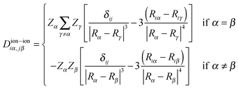
It is also possible to use the formalism to compute vibrational properties for finite and periodic systems.46,59 Currently Octopus implements the calculations of vibrations for finite systems. In this case the perturbation operator is an infinitesimal ionic displacement ∂Ĥ/∂Riα = ∂![[v with combining circumflex]](https://www.rsc.org/images/entities/i_char_0076_0302.gif) α/∂Riα, for each direction i and atom α. The quantity to calculate is the dynamical matrix, or Hessian, given by
α/∂Riα, for each direction i and atom α. The quantity to calculate is the dynamical matrix, or Hessian, given by
 | (8) |
 | (9) |
Vibrational frequencies ω are obtained by solving the eigenvalue equation
 | (10) |
The Born effective charges can be computed from the response of the dipole moment to ionic displacement:
 | (11) |
 | (12) |
The Born charges must obey the acoustic sum rule, from translational invariance
 | (13) |
 | (14) |
By mixing the response to ionic displacements and electric perturbations it is possible to calculate vibrational Raman response coefficients.60 This feature however, it is still not implemented in Octopus.
The Sternheimer equation can be used in conjunction with k·p perturbation theory61 to obtain band velocities and effective masses, as well as to apply electric fields via the quantum theory of polarization. In this case the perturbation is a displacement in the k-point. Using the effective Hamiltonian for the k-point
| Ĥk = e−ik·rĤeik·r, | (15) |
 | (16) |
 | (17) |
Inverse effective mass tensors can be calculated by solving the Sternheimer equation for the k·p perturbation. The equation is not solved self-consistently, since the variation of k-point is not a physical perturbation to the system; a converged k-grid should give the same density even if displaced slightly. The perturbation ∂Ĥk/∂k is purely anti-Hermitian. We use instead −i∂Ĥk/∂k to obtain a Hermitian perturbation, which allows the response to real wavefunctions to remain real. The effective mass tensors are calculated as follows:
 | (18) |
The k·p wavefunctions can be used to compute the response to electric fields in periodic systems. In finite systems, a homogeneous electric field can be represented simply via the position operator r. However, this operator is not well defined in a periodic system and cannot be used. According to the quantum theory of polarization, the solution is to replace rφ with −i∂φ/∂k,62 and then use this as the perturbation on the right hand side in the Sternheimer equation.63 While this is typically done with a finite difference with respect to k,49,64 we use an analytic derivative from a previous k·p Sternheimer calculation. Using the results in eqn (7) gives a formula for the polarization of the crystal:
 | (19) |
 | (20) |
We can compute the Born charges from the electric-field response in either finite or periodic systems (as a complementary approach to using the vibrational response):
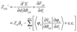 | (21) |
Unfortunately, the k·p perturbation is not usable to calculate the polarization,62 and a sum over strings of k-points on a finer grid is required. We have implemented the special case of a Γ-point calculation for a large super-cell, where the single-point Berry phase can be used.65 For cell sizes Li in each direction, the dipole moment is derived from the determinant of a matrix whose basis is the occupied KS orbitals:
 | (22) |
4 Magnetic response and gauge invariance in real-space grids
In the presence of a magnetic field B(r,t), generated by a vector potential A(r,t), additional terms describing the coupling of the electrons to the magnetic field must be included in the Hamiltonian | (23) |
As our main interest is the evaluation of the magnetic susceptibility, in the following, we consider a perturbative uniform static magnetic field B applied to a finite system with zero total spin. In the Coulomb gauge the corresponding vector potential, A, is given as
 | (24) |
 | (25) |
![[L with combining circumflex]](https://www.rsc.org/images/entities/i_char_004c_0302.gif) the angular momentum operator, and
the angular momentum operator, and | (26) |
The induced magnetic moment can be expanded in terms of the external magnetic field which, to first order, reads
 | (27) |
 | (28) |
 | (29) |
In numerical implementations, the gauge freedom in choosing the vector potential might lead to poor convergence with the quality of the discretization, and to a dependence of the magnetic response on the origin of the simulation cell. In other words, an arbitrary translation of the molecule could introduce an nonphysical change in the calculated observables. This broken gauge-invariance is well known in molecular calculations with all-electron methods that make use of localized basis sets. In this case, the error can be traced to the finite-basis-set representation of the wave-functions.66,67 A simple measure of the error is to check for the fulfillment of the hyper-virial relation.68
i〈φj|![[p with combining circumflex]](https://www.rsc.org/images/entities/b_i_char_0070_0302.gif) |φn〉 = (εn − εj)〈φj| |φn〉 = (εn − εj)〈φj|![[r with combining circumflex]](https://www.rsc.org/images/entities/b_i_char_0072_0302.gif) |φn〉, |φn〉, | (30) |
When working with a real-space mesh, this problem also appears, though it is milder, because the standard operator representation in the grid is not gauge-invariant. In this case the error can be controlled by reducing the spacing of the mesh. On the other hand, real-space grids usually require the use of the pseudo-potential approximation, where the electron–ion interaction is described by a non-local potential ![[v with combining circumflex]](https://www.rsc.org/images/entities/i_char_0076_0302.gif) nl. This, or any other non-local potential, introduces a fundamental problem when describing the interaction with magnetic fields or vector potentials in general. To preserve gauge invariance, this term must be adequately coupled to the external electromagnetic field, otherwise the results will strongly depend on the origin of the gauge. For example, an extra term has to be included in the hyper-virial expression, eqn (30), resulting in
nl. This, or any other non-local potential, introduces a fundamental problem when describing the interaction with magnetic fields or vector potentials in general. To preserve gauge invariance, this term must be adequately coupled to the external electromagnetic field, otherwise the results will strongly depend on the origin of the gauge. For example, an extra term has to be included in the hyper-virial expression, eqn (30), resulting in
i〈φj|![[p with combining circumflex]](https://www.rsc.org/images/entities/b_i_char_0070_0302.gif) |φn〉 = (εn − εj)〈φj| |φn〉 = (εn − εj)〈φj|![[r with combining circumflex]](https://www.rsc.org/images/entities/b_i_char_0072_0302.gif) |φn〉 + 〈φj|[ |φn〉 + 〈φj|[![[r with combining circumflex]](https://www.rsc.org/images/entities/b_i_char_0072_0302.gif) , ,![[v with combining circumflex]](https://www.rsc.org/images/entities/i_char_0076_0302.gif) nl]|φn〉. nl]|φn〉. | (31) |
 | (32) |
In order to calculate the corrections required to the magnetic perturbation operators, we use two different integration paths that have been suggested in the literature. The first was proposed by Ismail-Beigi, Chang, and Louie (ICL)69 who give the following correction to the first-order magnetic perturbation term
 | (33) |
 | (34) |
![[v with combining circumflex]](https://www.rsc.org/images/entities/i_char_0076_0302.gif) αnl are, respectively, the position and non-local potential of atom α. With the inclusion of either one of these methods, both implemented in Octopus, we recover gauge invariance in our formalism when pseudo-potentials are used. This allows us to predict the magnetic susceptibility and other properties that depend on magnetic observables, like optical activity.71
αnl are, respectively, the position and non-local potential of atom α. With the inclusion of either one of these methods, both implemented in Octopus, we recover gauge invariance in our formalism when pseudo-potentials are used. This allows us to predict the magnetic susceptibility and other properties that depend on magnetic observables, like optical activity.71
A class of systems with interesting magnetic susceptibilities are fullerenes. For example, it is known that the C60 fullerene has a very small magnetic susceptibility due to the cancellation of the paramagnetic and diamagnetic responses.72,73 Botti et al.74 used the real-space implementation of Octopus to study the magnetic response of the boron fullerenes depicted in Fig. 1. As shown in Table 1, they found that, while most clusters are diamagnetic, B80 is paramagnetic, with a strong cancellation of the paramagnetic and diamagnetic terms.
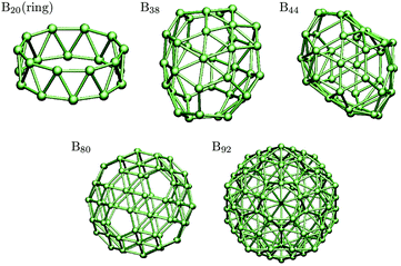 | ||
| Fig. 1 Structures of boron cages whose magnetic susceptibilities are given in Table 1. | ||
| Cluster |
![[small chi, Greek, macron]](https://www.rsc.org/images/entities/i_char_e0d8.gif)
|
|---|---|
| B20 | −250.2 |
| B38 | −468.3 |
| B44 | −614.4 |
| B80 | 219.3 |
| B92 | −831.3 |
5 Linear response in the electron–hole basis
An alternate approach to linear response is not to solve for the response function but rather for its poles (the excitation energies ωk) and residues (e.g. electric dipole matrix elements dk).75 The polarizability is given by | (35) |
 | (36) |
![[small alpha, Greek, tilde]](https://www.rsc.org/images/entities/i_char_e0dc.gif) is the fine-structure constant. The simplest approximation to use is the random-phase approximation (RPA), in which the excitation energies are given by the differences of unoccupied and occupied KS eigenvalues, ωcv = εc − εv. The corresponding dipole matrix elements are dcv = 〈φc|r|φv〉.76 (As implemented in the code, this section will refer only to the case of a system without partially occupied levels.)
is the fine-structure constant. The simplest approximation to use is the random-phase approximation (RPA), in which the excitation energies are given by the differences of unoccupied and occupied KS eigenvalues, ωcv = εc − εv. The corresponding dipole matrix elements are dcv = 〈φc|r|φv〉.76 (As implemented in the code, this section will refer only to the case of a system without partially occupied levels.)
The RPA is not a very satisfactory approximation, however. The full solution within TDDFT is given by a non-Hermitian matrix eigenvalue equation, with a basis consisting of both occupied–unoccupied (v → c) and unoccupied–occupied (c → v) KS transitions. The equation reads as
 | (37) |
〈φc′|〈φv′|A|φc〉|φv〉 = (εc − εv)δcc′δvv′ + 〈φc′|〈φv′|![[v with combining circumflex]](https://www.rsc.org/images/entities/i_char_0076_0302.gif) c + c + ![[f with combining circumflex]](https://www.rsc.org/images/entities/i_char_0066_0302.gif) xc|φc〉|φv〉, xc|φc〉|φv〉, | (38) |
〈φc′|〈φv′|B|φc〉|φv〉 = 〈φc′|〈φv′|![[v with combining circumflex]](https://www.rsc.org/images/entities/i_char_0076_0302.gif) c + c + ![[f with combining circumflex]](https://www.rsc.org/images/entities/i_char_0066_0302.gif) xc|φc〉|φv〉. xc|φc〉|φv〉. | (39) |
![[v with combining circumflex]](https://www.rsc.org/images/entities/i_char_0076_0302.gif) c is the Coulomb kernel, and
c is the Coulomb kernel, and ![[f with combining circumflex]](https://www.rsc.org/images/entities/i_char_0066_0302.gif) xc is the exchange–correlation kernel. Currently, only the kernel for LDA-type functionals is supported in Octopus. The implementation for more advanced functionals is planned for future releases.
xc is the exchange–correlation kernel. Currently, only the kernel for LDA-type functionals is supported in Octopus. The implementation for more advanced functionals is planned for future releases.
We do not solve the full equation in Octopus, but provide a hierarchy of approximations. An example calculation for the N2 molecule with each theory level is shown in Table 2. The lowest approximation we use is RPA. The next is the single-pole approximation of Petersilka et al.,77 in which only the diagonal elements of the matrix are considered. Like in the RPA case, the eigenvectors and dipole matrix elements are simply the KS transitions. The positive eigenvalues are ωcv = εc − εv + Acvcv. This can be a reasonable approximation when there is little mixing between KS transitions, but generally fails when there are degenerate or nearly degenerate transitions.
| RPA | Petersilka | TDA | Casida | CV(2) | Exp't |
|---|---|---|---|---|---|
| 8.234 | 9.421 | 9.343 | 9.254 | 9.671 | 9.309 |
| 8.234 | 9.421 | 9.343 | 9.254 | 10.279 | 9.309 |
| 9.671 | 9.671 | 9.671 | 9.671 | 10.279 | 9.921 |
| 9.671 | 10.241 | 10.237 | 10.221 | 10.792 | 10.270 |
| 9.671 | 10.245 | 10.241 | 10.224 | 10.801 | 10.270 |
| 9.671 | 11.028 | 10.931 | 10.921 | 11.077 | 12.199 |
A next level of approximation is the Tamm–Dancoff approximation to TDDFT78 in which the B blocks are neglected and thus we need only consider the occupied–unoccupied transitions. The matrix equation is reduced to a Hermitian problem of half the size of the full problem:
| Ax = ωx. | (40) |
 | (41) |
When the wavefunctions are real, the full problem can be collapsed into a Hermitian one of the same size as the Tamm–Dancoff matrix, known as Casida's equation.80,81
 | (42) |
 | (43) |
An alternate approach for finding excitation energies is to look for many-body eigenstates of the DFT Hamiltonian which are orthogonal to the ground state. In the “second-order constrained variational” or CV(2) theory,82 second-order perturbation theory from the ground-state density yields equations quite similar to the linear-response approach, despite their different origin:
 | (44) |
| (A + B)x = ωx. | (45) |
Note that all the levels of theory we have discussed use the same Coulomb and ![[f with combining circumflex]](https://www.rsc.org/images/entities/i_char_0066_0302.gif) xc matrix elements, so the code can calculate the results for multiple levels of theory with a small extra effort. We can also consider alternative perturbations in this framework beyond the dipole approximation for properties such as inelastic X-ray scattering.83
xc matrix elements, so the code can calculate the results for multiple levels of theory with a small extra effort. We can also consider alternative perturbations in this framework beyond the dipole approximation for properties such as inelastic X-ray scattering.83
For a non-spin-polarized system, the excitations separate into a singlet and a triplet subspace, which are superpositions of singlet and triplet KS transitions:
 | (46) |
 | (47) |
〈φS|![[v with combining circumflex]](https://www.rsc.org/images/entities/i_char_0076_0302.gif) c + c + ![[f with combining circumflex]](https://www.rsc.org/images/entities/i_char_0066_0302.gif) xc|φS〉 = 〈φ| xc|φS〉 = 〈φ|![[v with combining circumflex]](https://www.rsc.org/images/entities/i_char_0076_0302.gif) c + c + ![[f with combining circumflex]](https://www.rsc.org/images/entities/i_char_0066_0302.gif) ↑↑xc + ↑↑xc + ![[f with combining circumflex]](https://www.rsc.org/images/entities/i_char_0066_0302.gif) ↑↓xc|φ〉 = 〈φ| ↑↓xc|φ〉 = 〈φ|![[v with combining circumflex]](https://www.rsc.org/images/entities/i_char_0076_0302.gif) c + 2 c + 2![[f with combining circumflex]](https://www.rsc.org/images/entities/i_char_0066_0302.gif) xc|φ〉 xc|φ〉 | (48) |
〈φT|![[v with combining circumflex]](https://www.rsc.org/images/entities/i_char_0076_0302.gif) c + c + ![[f with combining circumflex]](https://www.rsc.org/images/entities/i_char_0066_0302.gif) xc|φT〉 = 〈φ| xc|φT〉 = 〈φ|![[f with combining circumflex]](https://www.rsc.org/images/entities/i_char_0066_0302.gif) ↑↑xc − ↑↑xc − ![[f with combining circumflex]](https://www.rsc.org/images/entities/i_char_0066_0302.gif) ↑↓xc|φ〉. ↑↓xc|φ〉. | (49) |
There are three main steps in the calculation: calculation of the matrix, diagonalization of the matrix, and calculation of the dipole matrix elements. The first step generally takes almost all the computation time, and is the most important to optimize. Within that step, the Coulomb part (since it is non-local) is much more time-consuming than the ![[f with combining circumflex]](https://www.rsc.org/images/entities/i_char_0066_0302.gif) xc part. We calculate it by solving the Poisson equation (as for the Hartree potential) for each column of the matrix, to obtain a potential P for the density φc(r)*φv(r), and then for each row computing the matrix element as
xc part. We calculate it by solving the Poisson equation (as for the Hartree potential) for each column of the matrix, to obtain a potential P for the density φc(r)*φv(r), and then for each row computing the matrix element as
| 〈φc′φv′|v|φcφv〉 = ∫drφc′(r)φv′(r)P[φcφv]. | (50) |
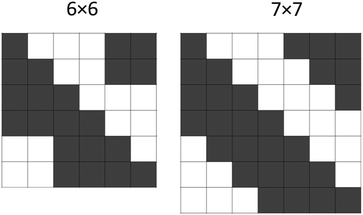
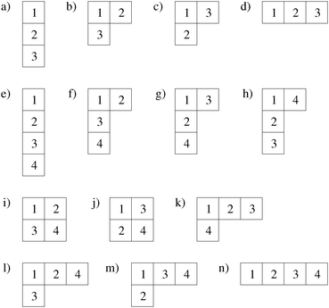
Our basic parallelization strategy for computation of the matrix elements is by domains, as discussed in Section 15, but we add an additional level of parallelization here over occupied–unoccupied pairs. We distribute the columns of the matrix, and do not distribute the rows, to avoid duplication of Poisson solves. We can reduce the number of matrix elements to be computed by almost half using the Hermitian nature of the matrix, i.e. Mcv,c′v′ = Mc′v′,cv*. If there are N occupied–unoccupied pairs, there are N diagonal matrix elements, and the N(N − 1)/2 remaining off-diagonal matrix elements are distributed as evenly as possible among the columns. If N − 1 is even, there are (N − 1)/2 for each column; if N − 1 is odd, half of the columns have N/2 − 1 and half have N/2. See Fig. 2 for examples of the distribution. The columns then are assigned to the available processors in a round-robin fashion. The diagonalization step is performed by direct diagonalization with LAPACK86 in serial; since it generally accounts for only a small part of the computation time, parallelization of this step is not very important. The final step is calculation of the dipole matrix elements, which amounts to only a small part of the computation time, and uses only domain parallelization. Note that the triplet kernel lacks the Coulomb term, and so is considerably faster to compute.
Using the result of a calculation of excited states by one of these methods, and a previous calculation of vibrational modes with the Sternheimer equation, we can compute forces in each excited state, which can be used for excited-state structural relaxation or molecular dynamics.87 Our formulation allows us to do this without introducing any extra summations over empty states, unlike previous force implementations.88–90 The energy of a given excited state k is a sum of the ground-state energy and the excitation energy: Ek = E0 + ωk. The force is then given by the ground-state force, minus the derivative of the excitation energy:
 | (51) |
 | (52) |
 | (53) |
6 Forces and geometry optimization on real-space grids
A function represented on a real-space grid is not invariant under translations as one would expect from a physical system. The potential of an atom sitting on top of a grid point might be slightly different from the potential of the same atom located between points. This implies that a rigid displacement of the system produces an artificial variation of the energy and other properties. If we plot the energy of the atom as a function of this rigid displacement, the energy shows an oscillation that gives this phenomenon the name of the “egg-box effect”.The egg-box effect is particularly problematic for calculations where the atoms are allowed to move, for example to study the dynamics of the atoms (molecular dynamics) or to find the minimum energy configuration (geometry optimization).
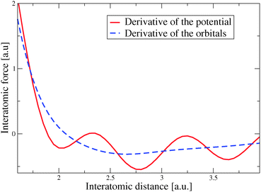
In Octopus we have studied several schemes to control the egg-box effect.91 The first step is to use pseudo-potential filtering to eliminate Fourier components of the potential that cannot be represented on the grid.92
Additionally, we have found a formulation for the forces that reduces the spurious effect of the grid on the calculations. One term in the forces is the expectation value of the derivative of the ionic potential with respect to the ionic position Rα, which can be evaluated as
 | (54) |
 | (55) |
This alternative formulation of the forces can be extended to obtain the second-order derivatives of the energy with respect to the atomic displacements,91 which are required to calculate vibrational properties as discussed in Section 3. In general, the perturbation operator associated with an ionic displacement can be written as
 | (56) |
 | (57) |
 | (58) |
With our approach, the forces tend to converge faster with the grid spacing than the energy. This means that to perform geometry optimizations it would be ideal to have a local minimization method that only relies on the forces, without needing to evaluate the energy, as both values will not be entirely consistent. Such a method is the fast inertial relaxation engine (FIRE) algorithm, put forward by Bitzek et al.94 FIRE has shown a competitive performance compared with both the standard conjugate-gradient method, and more sophisticated variations typically used in ab initio calculations. A recent article shows also the FIRE as one of the most convenient algorithm due to its speed and precision to reach the nearest local minimum starting from a given initial configuration.95
The FIRE algorithm is based on molecular dynamics with additional velocity modifications and adaptive time steps which only requires first derivatives of the target function. In the FIRE algorithm, the system slides down the potential-energy surface, gathering “momentum” until the direction of the gradient changes, at which point it stops, resets the adaptive parameters, and resumes sliding. This gain of momentum is done through the modification of the time step Δt as adaptive parameter, and by introducing the following velocity modification
v(t) → V(t) = (1 − α)v(t) + α|v(t)|![[F with combining circumflex]](https://www.rsc.org/images/entities/i_char_0046_0302.gif) (t), (t), | (59) |
![[F with combining circumflex]](https://www.rsc.org/images/entities/i_char_0046_0302.gif) is a unitary vector in the direction of the force F. By doing this velocity modification, the acceleration of the atoms is given by
is a unitary vector in the direction of the force F. By doing this velocity modification, the acceleration of the atoms is given by | (60) |
![[v with combining dot above]](https://www.rsc.org/images/entities/b_i_char_0076_0307.gif) (t) = F(t)/m, as usual.
(t) = F(t)/m, as usual.
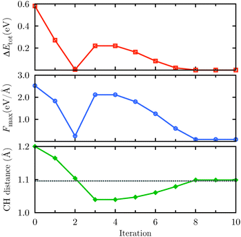
We illustrate how the algorithm works with a simple case: the geometry optimization of a methane molecule. The input geometry consists of one carbon atom at the center of a tetrahedron, and four hydrogen atoms at the vertices, where the initial C–H distance is 1.2 Å. In Fig. 4 we plot the energy difference ΔEtot with respect to the equilibrium conformation, the maximum component of the force acting on the ions Fmax, and the C–H bond length. On the first iterations, the geometry approaches the equilibrium position, but moves away on the 3rd. This means a change in the direction of the gradient, so there is no movement in the 4th iteration, the adaptive parameters are reset, and sliding resumes in the 5th iteration.
7 Photoemission
Electron photoemission embraces all the processes where an atom, a molecule or a surface is ionized under the effect of an external electromagnetic field. In experiments, the ejected electrons are measured with detectors that are capable of characterizing their kinetic properties. Energy-resolved, P(E), and momentum-resolved, P(k), photoemission probabilities are quite interesting observables since they carry important information, for instance, on the parent ion96,97 or on the ionization process itself.98 The calculation of these quantities is a difficult task because the process requires the evaluation of the total wavefunction in an extremely large portion of space (in principle a macroscopic one) that would be impractical to represent in real space.We have developed a scheme to calculate photoemission based on real-time TDDFT that is currently implemented in Octopus. We use a mixed real- and momentum-space approach. Each KS orbital is propagated in real space on a restricted simulation box, and then matched at the boundary with a momentum-space representation.
The matching is made with the help of a mask function M(r), like the one shown in Fig. 5, that separates each orbital into a bounded ϕAi(r) and an unbounded component ϕBi(r) as follows:
 | (61) |
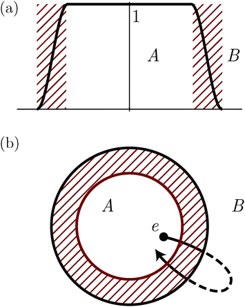 | ||
| Fig. 5 Scheme illustrating the mask method for the calculation of electron photoemission. A mask function (a) is used to effectively split each Kohn–Sham orbital into bounded and unbounded components localized in different spatial regions A and B according to the diagram in (b). In A the states are represented on a real-space grid while in B they are described in momentum space. A striped region indicates the volume where the two representations overlap. The propagation scheme of eqn (62) and (66) allows seamless transitions from one representations to the other and is capable to describe electrons following closed trajectories like the one in (b). | ||
Starting from a set of orbitals localized in A at t = 0 it is possible to derive a time-propagation scheme with time step Δt by recursively applying the discrete time-evolution operator Û(Δt) ≡ Û(t + Δt,t) and splitting the components with eqn (61). The result can be written in a closed form for ϕAi(r,t), represented in real space, and ϕBi(k,t), in momentum space, with the following structure:
| ϕAi(r,t + Δt) = φAi(r,t + Δt) + φBi(r,t + Δt), |
| ϕBi(k,t + Δt) = ϑAi(k,t + Δt) + ϑBi(k,t + Δt), | (62) |
| φAi(r,t + Δt) = MÛ(Δt)ϕAi(r,t), | (63) |
 | (64) |
 | (65) |
 | (66) |
 | (67) |
In eqn (66) we introduced the Volkov propagator Ûv(Δt) for the wavefunctions in B. It is the time-evolution operator associated with the Hamiltonian Ĥv describing free electrons in an oscillating field. Given a time dependent vector field A(t), the Hamiltonian  expressed in the velocity gauge is diagonal in momentum and can be naturally applied to ϕBi(k,t).
For all systems that can be described by a Hamiltonian such that Ĥ(r,t) = Ĥv(r,t) for r ∈ B and all time t, eqn (62) and (66) are equivalent to a time propagation in the entire space A ∪ B. In particular, it exactly describes situations where the electrons follow trajectories crossing the boundary separating A and B as illustrated in Fig. 5(b).
In Octopus we discretize eqn (66) in real and momentum space and co-propagate the complete set of orbitals ϕAi(r,t) and ϕBi(k,t). The propagation has to take care of additional details since the discretization can introduce numerical instability. In fact, substituting the Fourier integrals in (66) with Fourier sums (usually evaluated with FFTs) imposes periodic boundary conditions that spuriously reintroduces charge that was supposed to disappear. This is illustrated with a one-dimensional example in Fig. 6(a) where a wavepacket launched towards the left edge of the simulation box reappears from the other edge.
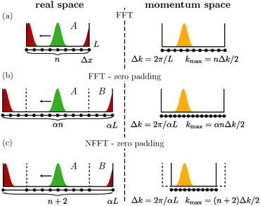 | ||
| Fig. 6 Scheme illustrating different discretization strategies for eqn (66) in one dimension. In all the cases an initial wavepacket (green) is launched towards the left side of a simulation box of length L and discretized in n sampling points spaced by Δx. A and B indicate the space partitions corresponding to Fig. 5. Owing to the discretization of the Fourier integrals, periodic conditions are imposed at the boundaries and the wavepacket wraps around the edges of the simulation box (red). The time evolution is portrayed together with a momentum-space representation (yellow), with spacing Δk and maximum momentum kmax, in three situations differing in the strategy used to map real and momentum spaces: (a) fast Fourier transform (FFT), (b) FFT extended with zeros (zero padding) in a box enlarged by a factor α, and (c) zero padding with NFFT. | ||
An alternative discretization strategy is zero padding. This is done by embedding the system into a simulation box enlarged by a factor α > 1, extending the orbitals with zeros in the outer region as shown in Fig. 6(b). In this way, the periodic boundaries are pushed away from the simulation box and the wavepackets have to travel an additional distance 2(α − 1)L before reappearing from the other side. In doing so, the computational cost is increased by adding (α − 1)n points for each orbital.
This cost can be greatly reduced using a special grid with only two additional points placed at ±αL as shown in Fig. 6(c). Since the new grid has non uniform spacing a non-equispaced FFT (NFFT) is used.100,101 With this strategy, a price is paid in momentum space where the maximum momentum kmax is reduced by a factor α compared to ordinary FFT. In Octopus we implemented all three strategies: bare FFT, zero padding with FFT and zero padding with NFFT.
All these discretization strategies are numerically stable for a propagation time approximately equivalent to the time that it takes for a wavepacket with the highest momentum considered to be reintroduced in the simulation box. For longer times we can employ a modified set of equations. It can be derived from (68) under the assumption that the electron flow is only outgoing. In this case we can drop the equation for φBi responsible for the ingoing flow and obtain the set
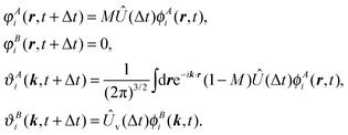 | (68) |
We conclude briefly summarizing some of the most important features and applications of our approach. The method allows us to retrieve P(k), the most resolved quantity available in experiments nowadays. In addition, it is very flexible with respect to the definition of the external field and can operate in a wide range of situations. In the strong-field regime, it can handle interesting situations, for instance, when the electrons follow trajectories extending beyond the simulation box, or when the target system is a large molecule. This constitutes a step forward compared to the standard theoretical tools employed in the field which, in the large majority of cases, invoke the single-active-electron approximation. In ref. 99 the code was successfully employed to study the photoelectron angular distributions of nitrogen dimers under a strong infrared laser field. The method can efficiently describe situations where more than one laser pulse is involved. This includes, for instance, time-resolved measurements where pump and probe setups are employed. In ref. 103 Octopus was used to monitor the time evolution of the π → π* transition in ethylene molecules with photoelectrons. The study was later extended to include the effect of moving ions at the classical level.104 Finally, we point out that our method is by no means restricted to the study of light-induced ionization but can be applied to characterize ionization induced by other processes, for example, ionization taking place after a proton collision.
8 Complex scaling and resonances
In this section we discuss the calculation of resonant electronic states by means of the complex-scaling method, as implemented in Octopus. By “resonant states,” we mean metastable electronic states of finite systems, such as atoms or molecules, with a characteristic energy and lifetime.Mathematically, resonances can be defined as poles of the scattering matrix or cross-section at complex energies.105,106 If a pole is close to the real energy axis, it will produce a large, narrow peak in the cross-section of scattered continuum states. One way resonances can arise is from application of an electric field strong enough to ionize the system through tunnelling. Resonant states may temporarily capture incoming electrons or electrons excited from bound states, making them important intermediate states in many processes.
The defining characteristic of a resonant state, often called a Siegert state,105 is that it has an outgoing component but not an incoming one. They can be determined by solving the time-independent Schrödinger equation with the boundary condition that the wavefunction must asymptotically have the form
 | (69) |
Resonant states are not eigenstates of any Hermitian operator and in particular do not reside within the Hilbert space. This precludes their direct calculation with the standard computational methods from DFT. However, it turns out that a suitably chosen analytic continuation of a Siegert state is localized, and this form can be used to derive information from the state. This is the idea behind the complex-scaling method107,108 where states and operators are represented by means of the transformation
![[R with combining circumflex]](https://www.rsc.org/images/entities/i_char_0052_0302.gif) θψ(r) = eiNθ/2ψ(reiθ), θψ(r) = eiNθ/2ψ(reiθ), | (70) |
![[R with combining circumflex]](https://www.rsc.org/images/entities/i_char_0052_0302.gif) θĤ
θĤ![[R with combining circumflex]](https://www.rsc.org/images/entities/i_char_0052_0302.gif) −θ.
−θ.
The Siegert states ψ(r) of the original Hamiltonian are square-integrable eigenstates ψθ(r) of Ĥθ, and their eigenvalues ε0 − iΓ/2 define the energy ε0 and width Γ of the resonance.109–111
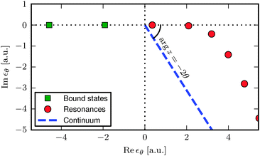
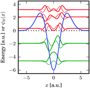
A typical example of a spectrum of the transformed Hamiltonian Ĥθ is shown in Fig. 7, and the corresponding potential and lowest bound and resonant states in Fig. 8. The bound-state energies are unchanged while the continuum rotates by −2θ around the origin. Finally, resonances appear as isolated eigenvalues in the fourth quadrant once θ is sufficiently large to “uncover” them from the continuum. Importantly, matrix elements (and in particular energies) of states are independent of θ as long as the states are localized and well represented numerically—this ensures that all physical bound-state characteristics of the untransformed Hamiltonian are retained.
Our implementation supports calculations with complex scaling for independent particles or in combination with DFT and selected xc functionals.112 The energy functional in KS-DFT consists of several terms that are all expressible as integrals of the density or the wavefunctions with the kinetic operator and various potentials. The functional is complex-scaled as per the prescribed method by rotating the real-space integration contour of every term by θ in the complex plane. The DFT energy functional becomes
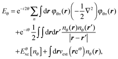 | (71) |
 | (72) |
In standard DFT, the KS equations are obtained by taking the functional derivative of the energy functional with respect to the density. Solving the equations corresponds to searching for a stationary point, with the idea that this minimizes the energy. In our case, since the energy functional is complex-valued,113 we cannot minimize the energy functional, but we can still search for stationary points to find the resonances.114,115 The complex-scaled version of the KS equations thereby becomes similar to the usual ones:
 | (73) |
 | (74) |
 | (75) |
 | (76) |
Fig. 9 shows calculated ionization rates for the He 1s state in a uniform Stark-type electric field as a function of field strength. In the limit of weak electric fields, the simple approximation by Ammosov, Delone and Krainov (ADK),116 which depends only on the ionization potential, approaches the accurate reference calculation by Scrinzi and co-workers.117 This demonstrates that the ionization rate is determined largely by the ionization potential for weak fields. As the local density approximation is known to produce inaccurate ionization potentials due to its wrong asymptotic form at large distances, it necessarily yields inaccurate rates at low fields. Meanwhile exact exchange, which is known to produce accurate ionization energies, predicts ionization rates much closer to the reference calculation. The key property of the xc functional that allows accurate determination of decay rates from complex-scaled DFT therefore appears to be that it must yield accurate ionization potentials, which is linked to its ability to reproduce the correct asymptotic form of the potential at large distances from the system.118
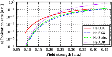 | ||
| Fig. 9 Ionization rates of the He atom in strong electric fields using the local density approximation (LDA) and exact exchange (EXX), compared to an accurate numerical ref. 117 as well as the analytic ADK approximation.116 Results from ref. 112. | ||
9 Quantum optimal control
In recent years, we have added to Octopus some of the key advancements of quantum optimal-control theory (QOCT).119,120 In this section, we will briefly summarize what this theory is about, overview the current status of its implementation, and describe some of the results that have been obtained with it until now.Quantum control can be loosely defined as the manipulation of physical processes at the quantum level. We are concerned here with the theoretical branch of this discipline, whose most general formulation is precisely QOCT. This is, in fact, a particular case of the general mathematical field of “optimal control”, which studies the optimization of dynamical processes in general. The first applications of optimal control in the quantum realm appeared in the 80s,121–123 and the field has rapidly evolved since then. Broadly speaking, QOCT attempts to answer the following question: given a quantum process governed by a Hamiltonian that depends on a set of parameters, what are the values of those parameters that maximize a given observable that depends on the behavior of the system? In mathematical terms: let a set of parameters u1,…,uM ≡ u determine the Hamiltonian of a system Ĥ[u,t], so that the evolution of the system also depends on the value taken by those parameters:
 | (77) |
| |ψ(0)〉 = |ψ0〉, | (78) |
Perhaps the most relevant result of QOCT is the equation for the gradient of G, which allows use of the various maximization algorithms available. For the simple formulation given above, this gradient is given by
 | (79) |
 | (80) |
 | (81) |
The first step is the selection of the parameters u, that constitute the search space. Frequently, these parameters are simply the values that the control function (typically, the electric-field amplitude) takes at the time intervals that are used to discretize the propagation interval, i.e. it is a “real-time parametrization”. However, more sophisticated parametrizations allow fine-tuning of the search space, introducing constraints and penalties into the formulation.
Then, one must choose an algorithm for maximizing multi-dimensional functions such as G. One possibility is the family of gradient-less algorithms, which only require a procedure to compute the value of the function, and do not need the gradient. In this case, the previous equations are obviously not needed. One only has to propagate the system forwards in time, which is what Octopus can do best. The value of the function G can then be computed from the evolution of ψ obtained with this propagation, and fed into the optimization procedure. A few gradient-less algorithms are implemented in Octopus.
The most efficient optimizations can be obtained if information about the gradient is employed. In that case, we can use standard schemes, such as the family of conjugate-gradient algorithms, or the Broyden–Fletcher–Goldfarb–Shanno (BFGS) quasi-Newton scheme – we use the implementation of these algorithms included in the GSL mathematical library.124 Some ad hoc algorithms, developed explicitly for QOCT, exist. These may in some circumstances be faster than the general purpose ones. Some of those are implemented in Octopus as well.125–127
In order to compute the gradient, one must implement a backwards-propagation scheme for the costate, which does not differ from the ones used for the normal forwards propagation.128 Note, however, that in some cases the backwards propagation does not have the exact same simple linear form than the forwards propagation, and may include inhomogeneous or non-linear terms. The final step is the computation of the gradient from the integral given in eqn (79).
The formulation of QOCT we have just sketched out is quite generic; in our case the quantum systems are those that can be modeled with Octopus (periodic systems are not supported at the moment), and the handle that is used to control the system is a time-dependent electric field, such as the ones that can be used to model a laser pulse. The set of parameters {u}i define the shape of this electric field; for example, they can be the Fourier coefficients of the field amplitude.
The usual formulation of QOCT assumes the linearity of quantum mechanics. However, the time-dependent KS equations are not linear, making both the theory and the numerics more complicated. We have extended the basic theory previously described to handle the TDDFT equations, and implemented the resulting equations in Octopus.129
We conclude this section by briefly describing some of the applications of the QOCT machinery included in Octopus, which can give an idea of the range of possibilities that can be attempted. The study presented in ref. 130 demonstrates the control of single-electron states in a two-dimensional semiconductor quantum-ring model. The states whose transitions are manipulated are the current-carrying states, which can be populated or de-populated with the help of circularly polarized light.
Ref. 131 studies double quantum dots, and shows how the electron state of these systems can be manipulated with the help of electric fields tailored by QOCT.
Another interesting application is how to tailor the shape of femtosecond laser pulses in order to obtain maximal ionization of atoms and molecules.132 The system chosen to demonstrate this possibility is the H2+ molecule, irradiated with short (≈5 fs) high-intensity laser pulses.
The feasibility of using the electronic current to define the target functional of the QOCT formalism is considered in ref. 133.
Finally, a series of works has studied the use of optimal control for photo-chemical control: the tailoring of laser pulses to create or break selected bonds in molecules. The underlying physical model should be based on TDDFT, and on a mixed quantum/classical scheme (within Octopus, Ehrenfest molecular dynamics). Some first attempts in this area were reported in ref. 134 and 135. However, these works did not consider a fully consistent optimal control theory encompassing TDDFT and Ehrenfest dynamics. This theory has been recently presented,136 and the first computations demonstrating its feasibility will be reported soon.
10 Plasmonics
The scope of real-space real-time approaches is not confined to the atomistic description of matter. For instance, finite-difference time-domain137 (FDTD) is a standard numerical tool of computational electromagnetism, while lattice Boltzmann methods138 (LBM) are widely used in computational fluid dynamics. Indeed, real-space real-time approaches can be used to model physical processes on rather different space and time scales. This observation also bears an important suggestion: numerical methods based on real-space grids can be used to bridge between these different space and time scales.Numerical nanoplasmonics is a paradigmatic case for multiscale electronic-structure calculations. A nanoplasmonic system – e.g., made up of metal nanoparticles (MNPs) – can be a few tens of nanometers across, while the region of strong field enhancement – e.g., in the gap between two MNPs – can be less than 1 nm across.139 The field enhancement, h(r), is essentially a classical observable, defined as
 | (82) |
In classical calculations, the electronic response is modeled by the macroscopic permittivity of the material. The classical Drude model gives the following simple and robust approximation of the metal (complex) permittivity:
 | (83) |
 | (84) |
 , where vF is the Fermi velocity, is suggested by the Thomas–Fermi approximation.144
Regardless of the level of sophistication of the permittivity model, all classical calculations assume that electrons are strictly confined inside the metal surfaces. This is a safe approximation for microscopic plasmonic structures. However, at the nanoscale the electronic delocalization (or spillout) outside the metal surfaces becomes comparable to the smallest features of the plasmonic nanostructure, e.g., to the gap between two MNPs. In this scale, the very definition of a macroscopic permittivity is inappropriate and the electronic response must be obtained directly from the quantum dynamics of the electrons.
TDDFT is currently the method of choice to model the plasmonic response of MNPs,145–151via the simplified jellium model, in which the nuclei and core electrons are described as a uniform positive charge density, and only the valence electrons are described explicitly. Early calculations – especially nanospheres146,152 – have suggested the existence of new charge-transfer plasmonic modes, which have been also demonstrated by pioneering experiments.139 In the future, as the field of quantum plasmonics153 – i.e., the investigation and control of the quantum properties of plasmons – will further develop, the demand for accurate, yet scalable, numerical simulations to complement the experimental findings is expected to grow. This demand represents both a challenge and an opportunity for computational physics.
Scaling up the TDDFT@jellium method to model larger and more complex plasmonic nanostructures is a challenge which can be addressed by high-performance real-space real-time codes, like Octopus. The code has been initially applied to investigate the plasmonic response of single gold nanospheres (Wigner–Seitz radius, rs = 3.0 bohr).147 A clear plasmonic resonance appears in the absorption cross section – computed by real-time propagation – for spheres containing a large enough number of electrons (Ne > 100). A new plasmonic mode, deemed the “quantum core plasmon”, has been also suggested from the analysis of the absorption cross-section. This new mode has been further characterized by probing the sphere at its resonance frequency. Within a real-time propagation scheme, this is simply done by including an external electric field, the “laser pulse”, oscillating at a given frequency.
As versatility is a major strength of real-space real-time approaches, other jellium geometries can be easily modeled by Octopus, including periodic structures. For instance, a pair of interacting sodium nanowires (with periodicity along their longitudinal direction) has been investigated to assess the accuracy of classical methods based on the model permittivity in eqn (83) and (84). Compared to pairs of nanospheres, nanowires display a stronger inductive interaction due to their extended geometry.148,149 This is manifest in the absorption cross-section which already shows a large split of the plasmonic peak for a small gap between the wires (see Fig. 10(a)). Due to the electronic spillout and the symmetry of the system, it also turns out that the largest field enhancement is reached at the center of the gap, not on the opposing surfaces of the nanowires as predicted by the classical methods (see Fig. 10(b)). The maximum field enhancement estimated by the TDDFT@jellium method is also smaller than the classical estimates. Once again, the quantum delocalization ignored by the classical methods plays a crucial role in “smearing” the singularities of the induced field, effectively curbing the local field enhancement.
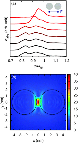 | ||
| Fig. 10 Panel (a): absorption cross section of a pair of sodium nanowires. The driving electric field is polarized as shown in the inset. Curves are for different values of gap, d, between the nanowires, from top to bottom: d = 5, 2, 1, 0.5, 0.2, 0.1, 0 nm. Panel (b): field enhancement, h, for the case d = 0.5 nm. The black lines indicate the nanowire surfaces. (Adapted from ref. 148). | ||
Simple jellium geometries have been implemented in Octopus and they can be used as effective “superatomic pseudopotentials”. The similarity between the jellium potential and atomic pseudopotentials can be further exploited to develop an external “jellium pseudopotential” generator to be used with Octopus. In this way, a larger selection of jellium geometries will be made available along with refined, yet scalable, jellium approaches to include d electron screening in noble metals.154 Efforts in this direction are being currently made.
Finally, a word of caution about the domain of applicability of the TDDFT@jellium method is in order. The non-uniformity of the atomic lattice is expected to affect the absorption cross-section of small MNPs. A careful assessment of the lattice contributions – including the lattice symmetry – on the main plasmon modes of a pair of nanosphere is available.151 This last investigation further demonstrates the possibility to bridge between atomistic and coarse-grained electronic calculations by means of a real-space real-time approach.
11 Development of exchange and correlation functionals
The central quantity of the KS scheme of DFT is the xc energy Exc[n], which describes all non-trivial many-body effects. Clearly, the exact form of this quantity is unknown and it must be approximated in any practical application of DFT. We emphasize that the accuracy of any DFT calculation depends solely on the form of this quantity, as this is the only real approximation in DFT (neglecting numerical approximations that are normally controllable).During the past 50 years, hundreds of different forms have appeared.155 They are usually arranged in families, which have names such as generalized-gradient approximations (GGAs), meta-GGAs, hybrid functionals, etc. In 2001, John Perdew came up with a beautiful idea on how to illustrate these families and their relationship.156 He ordered the families as rungs in a ladder that leads to the heaven of “chemical accuracy”, which he christened the “Jacob's ladder” of density-functional approximations for the xc energy. Every rung adds a dependency on another quantity, thereby increasing the precision of the functional but also increasing the numerical complexity and the computational cost.
The first three rungs of this ladder are: (i) the local-density approximation (LDA), where the functional has a local dependence on the density only; (ii) the generalized-gradient approximation (GGA), which includes also a local dependence on the gradient of the density; and (iii) the meta-GGA, which adds a local dependence on the Laplacian of the density and on the kinetic-energy density. In the fourth rung we have functionals that depend on the occupied KS orbitals, such as exact exchange or hybrid functionals. Finally, the fifth rung adds a dependence on the virtual KS orbitals.
Support for the first three rungs and for the local part of the hybrid functionals in Octopus is provided through the Libxc library.157 Libxc started as a spin-off project during the initial development of Octopus. At that point, it became clear that the task of evaluating the xc functional was completely independent of the main structure of the code, and could therefore be transformed into a stand-alone library. Over the years, Libxc became more and more independent of Octopus, and is now used in a variety of DFT codes. There are currently more than 150 xc functionals implemented in Libxc that are available in Octopus, a number that has been increasing steadily over the years. All of the standard functionals are included and many of the less common ones. There is also support for LDAs and GGAs of systems of reduced dimensionality (1D and 2D), which allow for direct comparisons with the direct solution of the many-body Schrödinger equation for model systems described in Section 13.
Octopus also includes support for other functionals of the fourth rung, such as exact exchange or the self-interaction correction of Perdew and Zunger,158 through the solution of the optimized effective potential equation. This can be done exactly,159 or within the Slater160 or Krieger-Li-Iafrate approximations.161
Besides the functionals that are supported by Octopus, the code has served as a platform for the testing and development of new functionals. For example, the method described in Section 13 can be used in a straightforward way to obtain reference data against which to benchmark the performance of a given xc functional, for example a one-dimensional LDA.162 In that case, both calculations, exact and approximate, make use of the same real-space grid approach, which makes the comparison of the results obtained with both straightforward. Despite the obvious advantage of using exact solutions of the many-body problem as reference data, this is often not possible and one usually needs to resort to the more commonly used experimental or highly-accurate quantum-chemistry data. In this case, the flexibility of the real-space method, allowing for the calculation of many different properties of a wide variety of systems, is again an advantage. Octopus has therefore been used to benchmark the performance of xc functionals whose potential has a correct asymptotic behavior163 when calculating ionization potentials and static polarizabilities of atoms, molecules, and hydrogen chains.
In this vein, Andrade and Aspuru-Guzik164 proposed a method to obtain an asymptotically correct xc potential starting from any approximation. Their method is based on considering the xc potential as an electrostatic potential generated by a fictitious xc charge. In terms of this charge, the asymptotic condition is given as a simple formula that is local in real space and can be enforced by a simple procedure. The method, implemented in Octopus, was used to perform test calculations in molecules. Additionally, with this correction procedure it is possible to find accurate predictions for the derivative discontinuity and, hence, predict the fundamental gap.165
12 Real-space reduced density-matrix functional theory
An alternative approach to DFT that can model electrons using a single-particle framework is reduced density matrix functional theory (RDMFT).166 Here, we present the current results of an ongoing effort to develop a real-space version of RDMFT and to implement it in the Octopus code.Within RDMFT, the total energy of a system is given as a functional of the one-body reduced density-matrix (1-RDM)
| γ(r,r′) = N∫⋯∫dr2…drNΨ*(r′,r2…rN)Ψ(r,r2…rN) | (85) |
 | (86) |
In RDMFT the total energy is given by
 | (87) |
 | (88) |
For closed-shell systems, the necessary and sufficient conditions for the 1-RDM to be N-representable,171i.e. to correspond to a N-electron wavefunction, is that 0 ≤ ni ≤ 2 and
 | (89) |
| 〈ϕi|ϕj〉 = δij. | (90) |
 | (91) |
The variation of Ω is done in two steps: for a fixed set of orbitals, the energy functional is minimized with respect to occupation numbers and, accordingly, for a fixed set of occupations the energy functional is minimized with respect to variations of the orbitals until overall convergence is achieved. As a starting point we use results from a Hartree–Fock calculation and first optimize the occupation numbers. Since the correct μ is not known, it is determined via bisection: for every μ the objective functional is minimized with respect to ϑi until the condition (89) is satisfied.
Due to the dependence on the occupation numbers, the natural-orbital minimization does not lead to an eigenvalue equation like in DFT or Hartree–Fock. The implementation of the natural orbital minimization follows the method by Piris and Ugalde.172 Varying Ω with respect to the orbitals for fixed occupation numbers one obtains
 | (92) |
| λji − λij* = 0. | (93) |
| Fji = θ(i − j)(λji − λij*) + θ(j − i)(λij* − λji), | (94) |
As mentioned above, one needs an initial guess for the natural orbitals both for the first step of occupation-number optimization but also for the optimization of the natural orbitals. A rather obvious choice would be the occupied and a few unoccupied orbitals resulting from a DFT or HF calculation. Unfortunately, there are unbound states among the HF/DFT unoccupied states which are a bad starting point for the weakly occupied natural orbitals. When calculated in a finite grid these orbitals are essentially the eigenstates of a particle in a box. Using the exact-exchange approximation (EXX) in an optimized-effective-potential framework results in a larger number of bound states than HF or the local density approximation (LDA) due to the EXX functional being self-interaction-free for both occupied and unoccupied orbitals. Using HF or LDA orbitals to start a RDMFT calculation, the natural orbitals do not converge to any reasonable shape, but even when starting from EXX one needs to further localize the unoccupied states. Thus, we have found that in order to improve the starting point for our calculation we can multiply each unoccupied orbital by a set of Gaussian functions centered at the positions of the atoms. As the unbound states are initially more delocalized than the bound ones, we choose a larger exponent for them.
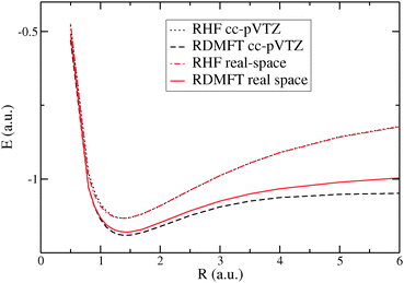
In Fig. 11 we show the dissociation curve of H2 obtained with RDMFT in Octopus and compare it with results obtained by the Gaussian-basis-set RDMFT code HIPPO.173 For the Octopus calculation, we kept 13 natural orbitals with the smallest occupation number being of the order of 10−5 after the RDMFT calculation had converged. The HIPPO calculation was performed using 30 natural orbitals. The RDMFT curve obtained with Octopus looks similar to the one from HIPPO and other Gaussian implementations of RDMFT,167 keeping the nice feature of not diverging strongly in the dissociation limit. However, for internuclear distances R bigger than 1 a.u., the real-space energy lies above the HIPPO one. We believe that the remaining difference can be removed by further improving the initial guess for the orbitals that we use in Octopus, because a trial calculation using HF orbitals from a Gaussian implementation showed a curve almost identical to the one from the HIPPO code (not shown in the figure). In the future, we plan to include support for open-shell systems and additional xc functionals.
13 Exact solution of the many-body Schrödinger equation for few electrons
In one-dimensional systems, the fully interacting Hamiltonian for N electrons has the form | (95) |
 , where a softening parameter (usually set to one) is introduced in order to avoid the divergence at xj = xk, which is non-integrable in 1D.
Mathematically, the Hamiltonian (eqn (95)) is equivalent to that of a single (and hence truly independent) electron in N dimensions, with the external potential
 | (96) |
| ĤΨj(x1…xN) = EjΨj(x1…xN) | (97) |
What we exploit in Octopus is the basic machinery for solving the Schrödinger equation in an arbitrary dimension, the spatial/grid bookkeeping, the ability to represent an arbitrary external potential, and the intrinsic parallelization. In order to keep our notation relatively simple, we will continue to discuss the case of an originally one-dimensional problem with N electrons. Grid-based solutions of the full Schrödinger equation are not new, and have been performed for many problems with either few electrons (in particular H2, D2 and H2+)174,175 or model interactions,176 including time-dependent cases.177
The time-dependent propagation of the Schrödinger equation can be carried out in the same spirit, since the Hamiltonian is given explicitly and each “single-particle orbital” represents a full state of the system. A laser or electric-field perturbation can also be applied, depending on the charge of each particle (given in the input), and taking care to apply the same effective field to each particle along the polarization direction of the field (in 1D, the diagonal of the hyper-cube).
Solving eqn (97) leaves the problem of constructing a wave function which satisfies the anti-symmetry properties of N electrons in one dimension. For fermions one needs to ensure that those spatial wave functions Ψj which are not the spatial part of a properly anti-symmetric wave function are removed as allowed solutions for the N-electron problem. A graphical representation of which wave functions are allowed is given by the Young diagrams (or tableaux) for permutation symmetries, where each electron is assigned a box, and the boxes are then stacked in columns and rows (for details see, for example, ref. 178). Each box is labeled with a number from 1 to N such that the numbers increase from top to bottom and left to right.
All possible decorated Young diagrams for three and four electrons are shown in Fig. 12. Since there are two different spin states for electrons, our Young diagrams for the allowed spatial wave functions contain at most two columns. The diagram (d) is not allowed for the wave function of three particles with spin 1/2, and diagrams (k) to (n) are not allowed for four particles. To connect a given wave function Ψj with a diagram one has to symmetrize the wave function according to the diagram. For example, for diagram (b) one would perform the following operations on a function Ψ(x1,x2,x3)
| [Ψ(x1,x2,x3) + Ψ(x2,x1,x3)] − [Ψ(x3,x2,x1) + Ψ(x3,x1,x2)]. | (98) |
For example, for a one-dimensional Li atom with an external potential
 | (99) |
| State | Energy | Young diagram | Norm |
|---|---|---|---|
| 1 | −4.721 | Bosonic | <10−13 |
| 2 | −4.211 | (b) | 0.2 |
| 3 | −4.211 | (c) | 0.6 |
| 4 | −4.086 | Bosonic | <10−11 |
| 5 | −4.052 | (b) | 0.4 |
| 6 | −4.052 | (c) | 0.7 |
If certain state energies are degenerate, the Young diagram “projection” contains an additional loop, ensuring that the same diagram is not used to symmetrize successive states: this would yield the same spatial part for each wave function in the degenerate sub-space. A given diagram is only used once in the sub-space, on the first state whose projection has significant weight.
The implementation also allows for the treatment of bosons, in which case the total wave function has to be symmetric under exchange of two particles. Here one will use a spin part symmetrized with the same Young diagram (instead of the mirror one for fermions), such that the total wave function becomes symmetric.
In order for the (anti-)symmetrization to work properly one needs to declare each particle in the calculation to be a fermion, a boson, or an anyon. In the latter case, the corresponding spatial variables are not considered at all in the (anti-)symmetrization procedure. One can also have more than one type of fermion or boson, in which case the symmetric requirements are only enforced for particles belonging to the same type.
There are also numerical constraints on the wave-functions: space must be represented in a homogeneous hyper-cube, eventually allowing for different particle masses by modifying the kinetic-energy operator for the corresponding directions. All of the grid-partitioning algorithms intrinsic to octopus carry over to arbitrary dimensions, which allows for immediate parallelization of the calculations of the ground and excited states. The code can run with an arbitrary number of dimensions, however, the complexity and memory size grow exponentially with the number of particles simulated, as expected. Production runs have been executed up to 6 or 7 dimensions.
Most of the additional treatment for many-body quantities is actually post-processing of the wave-functions. For each state, the determination of the fermionic or bosonic nature by Young-tableau symmetrization is followed by the calculation and output of the density for each given particle type, if several are present. Other properties of the many-body wave-function can also be calculated. For example, Octopus can also output the one-body density matrix, provided in terms of its occupation numbers and natural orbitals.
This type of studies, even when they are limited to model systems of a few electrons, allows us to produce results that can be compared to lower levels of theory like approximate DFT or RDMFT, and to develop better approximations for the exchange and correlation term. Exact results obtained from such calculations have been used to assess the quality of a 1D LDA functional162 and adiabatic 1D LDA and exact exchange in a TDDFT calculation calculation of photoemission spectra.162,179
14 Compressed sensing and atomistic simulations
In order to obtain frequency-resolved quantities from real-time methods like molecular dynamics or electron dynamics, it is necessary to perform a spectral representation of the time-resolved signal. This is a standard operation that is usually performed using a discrete Fourier transform. Since the resolution of the spectrum is given by the length of the time signal, it is interesting to look for more methods that can provide us a spectrum of similar quality with shorter time series, as this is directly reflected in shorter computation times. Several such methods exist, but a particular one that has been explored in Octopus, due to its general applicability and efficiency, is compressed sensing.Compressed sensing180 is a general theory aimed at optimizing the amount of sampling required to reconstruct a signal. It is based on the idea of sparsity, a measure of how many zero coefficients a signal has when represented in a certain basis. Compressed sensing has been applied to many problems in experimental sciences181–183 and technology184,185 in order to perform more accurate measurements. Its ideas, however, can also be applied to computational work.
In order to calculate a spectrum in compressed sensing, we need to solve the so-called basis-pursuit optimization problem
 | (100) |
 is the standard 1-norm, τ is the discretized time series, σ is the frequency-resolved function (the spectrum that we want to calculate) and F is the Fourier-transform matrix.
Since τ is a short signal, its dimension is smaller than the one of σ. This implies that the linear equation Fσ = τ is under-determined and has many solutions, in this particular case, all the spectra that are compatible with our short time propagation. From all of these possible solutions, eqn (100) takes the one that has the smallest 1-norm, that corresponds to the solution that has the most zero coefficients. For spectra, this means we are choosing the one with the fewest frequencies, which will tend to be the physical one, as for many cases we know that the spectra is composed of a discrete number of frequencies.
To solve eqn (100) numerically, we have implemented in Octopus the SPGL1 algorithm.186 The solution typically takes a few minutes, which is two orders of magnitude more expensive than the standard Fourier transform, but this is negligible in comparison with the cost of the time propagation.
By applying compressed sensing to the determination of absorptional or vibrational spectra, it was found that a time signal a fifth of the length can be used in comparison with the standard Fourier transform.35 This is translated into an impressive factor-of-five reduction in the computational time. This is illustrated in Fig. 13 where we show a spectrum calculated with compressed sensing from a 10 fs propagation, which has a resolution similar to a Fourier transform spectrum obtained with 50 fs of propagation time.
Moreover, the general conclusion that can be obtained from this work is that in the application of compressed sensing to simulations the reduction in the number of samples that compressed sensing produces in an experimental setup is translated into a reduction of the computational time. This concept inspired studies on how to carry the ideas of compressed sensing into the core of electronic-structure simulations. The first result of this effort is a method to use compressed sensing to reconstruct sparse matrices, that has direct application in the calculation of the Hessian matrix and vibrational frequencies from linear response (as discussed in Section 3). For this case, our method results in the reduction of the computational time by a factor of three.187
15 Parallelization, optimizations and graphics processing units
Computational cost has been and still is a fundamental factor in the development of electronic structure methods, as the small spatial dimensions and the fast movement of electrons severely limit the size of systems that can be simulated. In order to study systems of interest as realistically and accurately as possible, electronic-structure codes must execute efficiently in modern computational platforms. This implies support for massively parallel platforms and modern parallel processors, including graphics processing units (GPUs).Octopus has been shown to perform efficiently on parallel supercomputers, scaling to hundreds of thousands of cores.35,188 The code also has an implementation of GPU acceleration35,189 that has shown to be competitive in performance with Gaussian DFT running on GPUs.190
Performance is not only important for established methods, but also for the implementation of new ideas. The simplicity of real-space grids allows us to provide Octopus developers with building blocks that they can use to produce highly efficient code without needing to know the details of the implementation, isolating them as much as possible from the optimization and parallelization requirements. In most cases, these building blocks allow developers to write code that is automatically parallel, efficient, and that can transparently run on GPUs. The type of operations available run from simple ones, like integration, linear algebra, and differential operators, to more sophisticated ones, like the application of a Hamiltonian or solvers for differential equations.
However, it is critical to expose an interface with the adequate level that hides the performance details, while still giving enough flexibility to the developers. For example, we have found that the traditional picture of a state as the basic object is not adequate for optimal performance, as it does not expose enough data parallelism.189 In Octopus we use a higher-level interface where the basic object is a group of several states.
In the case of functions represented on the grid, the developers work with a linear array that contains the values of the field for each grid point. Additional data structures provide information about the grid structure. This level of abstraction makes it simple for developers to write code that works for different problem dimensionality, and different kinds and shapes of grids.
In terms of performance, by hiding the structure of the grid, we can use sophisticated methods to control how the grid points are stored in memory with the objective of using processor caches more efficiently in finite-difference operators. We have found that by using space-filling curves,191 as shown in Fig. 14, and in particular the Hilbert curve,192,193 we can produce a significant improvement in the performance of semi-local operations. For example, in Fig. 15 shows that a performance gain of around 50% can be obtained for the finite-difference Laplacian operator running on a GPU by using a Hilbert curve to map the grid into memory.
Parallelization in Octopus is performed on different levels. The most basic one is domain decomposition, were the grid is divided in different regions that are assigned to each processor. For most operations, only the boundaries of the regions need to be communicated among processors. Since the grid can have a complicated shape dictated by the shape of the molecule, it is far from trivial to distribute the grid-points among processors. For this task we use a third-party library called ParMETIS.194 This library provides routines to partition the grid ensuring a balance of points and minimizing the size of the boundary regions, and hence the communication costs. An example of grid partitioning is shown in Fig. 16.
Additional parallelization is provided by other data decomposition approaches that are combined with domain decomposition. This includes parallelization over KS states, and over k-points and spin. The latter parallelization strategy is quite efficient, since for each k-point or spin component the operations are independent. However, it is limited by the size of the system, and often is not available (as in the case of closed-shell molecules, for example).
The efficiency of the parallelization over KS states depends on the type of calculation being performed. For ground state calculations, the orthogonalization and subspace diagonalization routines195 require the communication of states. In Octopus this is handled by parallel dense linear-algebra operations provided by the ScaLAPACK library.196 For real-time propagation, on the other hand, the orthogonalization is preserved by the propagation34 and there is no need to communicate KS states between processors. This makes real-time TDDFT extremely efficient in massively parallel computers.35,197
An operation that needs special care in parallel is the solution of the Poisson equation. Otherwise, it constitutes a bottleneck in parallelization, as a single Poisson solution is required independently of the number of states in the system. A considerable effort has been devoted to the problem of finding efficient parallel Poisson solvers that can keep up with the rest of the code.198 We have found that the most efficient methods are based on FFTs, which require a different domain decomposition to perform efficiently. This introduces the additional problem of transferring the data between the two different data partitions. In Octopus this was overcome by creating a mapping at the initialization stage and using it during execution to efficiently communicate only the data that is strictly necessary between processors.188
16 Conclusions
In this article, we have shown several recent developments in the realm of electronic-structure theory that have been based on the Octopus real-space code and made possible in part by the flexibility and simplicity of working with real-space grids. Most of them go beyond a mere implementation of existing theory and represent new ideas in their respective areas. We expect that many of these approaches will become part of the standard tools of physicists, chemists and material scientists, and in the future will be integrated into other electronic-structure codes.These advances also illustrate the variety of applications of real-space electronic structure, many of which going beyond the traditional calculation schemes used in electronic structure, and might provide a way forward to tackle current and future challenges in the field.
What we have presented also shows some of the current challenges in real-space electronic structure. One example is the use of pseudo-potentials or other forms of projectors to represent the electron–ion interaction. Non-local potentials introduce additional complications on both the formulation, as shown by the case of magnetic response, and the implementation. Pseudo-potentials also include an additional, and in some cases, not well-controlled approximation. It would be interesting to study the possibility of developing an efficient method to perform full-potential calculations without additional computational cost, for example by using adaptive or radial grids.
Another challenge for real-space approaches is the cost of the calculation of two-body Coulomb integrals that appear in electron–hole linear response, RDMFT or hybrid xc functionals. In real-space these integrals are calculated in linear or quasi-linear time by considering them as a Poisson problem. However, the actual numerical cost can be quite large when compared with other operations. A fast approach to compute these integrals, perhaps by using an auxiliary basis, would certainly make the real-space approach more competitive for some applications.
The scalability of real-space grid methods makes them a good candidate for electronic-structure simulations in the future exaflop supercomputing systems expected for the end of the decade. In this aspect, the challenge is to develop high-performance implementations that can run efficiently on these machines.
Acknowledgements
We would like to thank all the people that have contributed to Octopus and to the development and implementation of the applications presented in this article. In particular we would like to acknowledge Pablo García-Risueño (for his contribution to the development of scalable Poisson solvers), Joaquim Jornet Somoza, Silvana Botti, Jacob Sanders, Johanna Fuks, Arto Sakko, Heiko Appel, Danilo Nitsche, Florian Lorenzen, Daniele Varsano, Carlo A. Rozzi, Roberto Olivares-Amaya, Alain Delgado, Pablo Garcia-González, Javier Muguerza, and Agustin Arruabarrena. XA acknowledges that part of this work was performed under the auspices of the U.S. Department of Energy at Lawrence Livermore National Laboratory under Contract DE-AC52-07A27344. XA and AA-G would like to thank the support received from Nvidia Corporation through the CUDA Center of Excellence program and the US Defense Threat Reduction Agency under contract no. HDTRA1-10-1-0046. DAS acknowledges support from the U.S. National Science Foundation graduate research program and IGERT fellowships, and from ARPA-E under grant DE-AR0000180. MJTO acknowledges financial support from the Belgian FNRS through FRFC project number 2.4545.12 “Control of attosecond dynamics: applications to molecular reactivity”. NH and IT received support from a Emmy-Noether grant from Deutsche Forschungsgemeinschaft. JAR, AV, UDG, AHL and AR ackowledge financial support by the European Research Council Advanced Grant DYNamo (ERC-2010-AdG-267374), European Commission project CRONOS (Grant number 280879-2 CRONOS CP-FP7), Marie Curie ITN POCAONTAS (FP7-PEOPLE-2012-ITN, project number 316633), OST Actions CM1204 (XLIC), and MP1306 (EUSpec), Spanish Grant (FIS2013-46159-C3-1-P) and Grupo Consolidado UPV/EHU del Gobierno Vasco (IT578-13). JAR acknowledges the Department of Education, Universities and Research of the Basque Government (grant IT395-10). AC acknowledges support from the grant FIS2013-46159-C3-2-P of the Spanish government. This article was written using Authorea.References
- P. Hohenberg and W. Kohn, Phys. Rev., 1964, 136, B864–B871 CrossRef.
- W. Kohn and L. J. Sham, Phys. Rev., 1965, 140, A1133–A1138 CrossRef.
- A. J. Cohen, P. Mori-Sanchez and W. Yang, Science, 2008, 321, 792–794 CrossRef CAS PubMed.
- A. Szabo and N. Ostlund, Modern Quantum Chemistry: Introduction to Advanced Electronic Structure Theory, Dover Publications, 1996 Search PubMed.
- R. Dovesi, R. Orlando, A. Erba, C. M. Zicovich-Wilson, B. Civalleri, S. Casassa, L. Maschio, M. Ferrabone, M. D. L. Pierre, P. DArco, Y. Noël, M. Causà, M. Rérat and B. Kirtman, Int. J. Quantum Chem., 2014, 114, 1287–1317 CrossRef CAS PubMed.
- S. White, J. Wilkins and M. Teter, Phys. Rev. B: Condens. Matter Mater. Phys., 1989, 39, 5819–5833 CrossRef.
- E. Tsuchida and M. Tsukada, Phys. Rev. B: Condens. Matter Mater. Phys., 1995, 52, 5573–5578 CrossRef CAS.
- R. J. Harrison, G. I. Fann, T. Yanai, Z. Gan and G. Beylkin, J. Chem. Phys., 2004, 121, 11587 CrossRef CAS PubMed.
- M. Stener, G. Fronzoni and P. Decleva, J. Chem. Phys., 2005, 122, 234301 CrossRef CAS PubMed.
- L. Genovese, B. Videau, M. Ospici, T. Deutsch, S. Goedecker and J.-F. Méhaut, C. R. Mec., 2011, 339, 149–164 CrossRef CAS PubMed.
- A. D. Becke, Int. J. Quantum Chem., 1989, 36, 599–609 CrossRef PubMed.
- J. Chelikowsky, N. Troullier and Y. Saad, Phys. Rev. Lett., 1994, 72, 1240–1243 CrossRef CAS.
- A. Seitsonen, M. Puska and R. Nieminen, Phys. Rev. B: Condens. Matter Mater. Phys., 1995, 51, 14057–14061 CrossRef CAS.
- T. Hoshi, M. Arai and T. Fujiwara, Phys. Rev. B: Condens. Matter Mater. Phys., 1995, 52, R5459–R5462 CrossRef CAS.
- F. Gygi and G. Galli, Phys. Rev. B: Condens. Matter Mater. Phys., 1995, 52, R2229–R2232 CrossRef CAS.
- E. Briggs, D. Sullivan and J. Bernholc, Phys. Rev. B: Condens. Matter Mater. Phys., 1996, 54, 14362–14375 CrossRef CAS.
- J.-L. Fattebert, BIT Numer. Math., 1996, 36, 509–522 CrossRef.
- T. L. Beck, Int. J. Quantum Chem., 1997, 65, 477–486 CrossRef CAS.
- T. Ono and K. Hirose, Phys. Rev. Lett., 1999, 82, 5016–5019 CrossRef CAS.
- T. Beck, Rev. Mod. Phys., 2000, 72, 1041–1080 CrossRef CAS.
- M. Nardelli, J.-L. Fattebert and J. Bernholc, Phys. Rev. B: Condens. Matter Mater. Phys., 2001, 64, 245423 CrossRef.
- M. A. L. Marques, A. Castro, G. F. Bertsch and A. Rubio, Comput. Phys. Commun., 2003, 151, 60–78 CrossRef CAS.
- J. Pask and P. Sterne, Phys. Rev. B: Condens. Matter Mater. Phys., 2005, 71, 113101 CrossRef.
- L. Kronik, A. Makmal, M. L. Tiago, M. M. G. Alemany, M. Jain, X. Huang, Y. Saadand and J. R. Chelikowsky, Phys. Status Solidi B, 2006, 243, 1063–1079 CrossRef CAS PubMed.
- R. Schmid, M. Tafipolsky, P. H. König and H. Köstler, Phys. Status Solidi B, 2006, 243, 1001–1015 CrossRef CAS PubMed.
- E. Krotscheck, E. R. Hernández, S. Janecek, M. S. Kaczmarski and R. Wahl, Eur. Phys. J. D, 2007, 43, 173–176 CrossRef CAS PubMed.
- J. Bernholc, M. Hodak and W. Lu, J. Phys.: Condens. Matter, 2008, 20, 294205 CrossRef.
- F. Shimojo, R. Kalia, A. Nakano and P. Vashishta, Phys. Rev. B: Condens. Matter Mater. Phys., 2008, 77, 085103 CrossRef.
- H. Goto and K. Hirose, J. Phys.: Condens. Matter, 2009, 21, 064231 CrossRef PubMed.
- J. Enkovaara, C. Rostgaard, J. J. Mortensen, J. Chen, M. Duak, L. Ferrighi, J. Gavnholt, C. Glinsvad, V. Haikola, H. A. Hansen, H. H. Kristoffersen, M. Kuisma, A. H. Larsen, L. Lehtovaara, M. Ljungberg, O. Lopez-Acevedo, P. G. Moses, J. Ojanen, T. Olsen, V. Petzold, N. A. Romero, J. Stausholm-Mller, M. Strange, G. A. Tritsaris, M. Vanin, M. Walter, B. Hammer, H. Häkkinen, G. K. H. Madsen, R. M. Nieminen, J. K. Nrskov, M. Puska, T. T. Rantala, J. Schitz, K. S. Thygesen and K. W. Jacobsen, J. Phys.: Condens. Matter, 2010, 22, 253202 CrossRef CAS PubMed.
- J.-I. Iwata, D. Takahashi, A. Oshiyama, T. Boku, K. Shiraishi, S. Okada and K. Yabana, J. Comput. Phys., 2010, 229, 2339–2363 CrossRef CAS PubMed.
- A. Sasaki, M. Kojo, K. Hirose and H. Goto, J. Phys.: Condens. Matter, 2011, 23, 434001 CrossRef PubMed.
- T. Ono, S. Tsukamoto, Y. Egami and Y. Fujimoto, J. Phys.: Condens. Matter, 2011, 23, 394203 CrossRef PubMed.
- A. Castro and M. A. L. Marques, Time-Dependent Density Functional Theory, Springer Science+Business Media, 2006, pp. 197–210 Search PubMed.
- X. Andrade, J. N. Sanders and A. Aspuru-Guzik, Proc. Natl. Acad. Sci. U. S. A., 2012, 109, 13928–13933 CrossRef CAS PubMed.
- M. A. L. Marques, A. Castro and A. Rubio, J. Chem. Phys., 2001, 115, 3006 CrossRef CAS PubMed.
- K. Yabana and G. Bertsch, Phys. Rev. B: Condens. Matter Mater. Phys., 1996, 54, 4484–4487 CrossRef CAS.
- G. Bertsch, J.-I. Iwata, A. Rubio and K. Yabana, Phys. Rev. B: Condens. Matter Mater. Phys., 2000, 62, 7998–8002 CrossRef CAS.
- R. Aggarwal, L. Farrar, S. Saikin, X. Andrade, A. Aspuru-Guzik and D. Polla, Solid State Commun., 2012, 152, 204–209 CrossRef CAS PubMed.
- J. Alonso, X. Andrade, P. Echenique, F. Falceto, D. Prada-Gracia and A. Rubio, Phys. Rev. Lett., 2008, 101, 096403 CrossRef CAS.
- X. Andrade, A. Castro, D. Zueco, J. L. Alonso, P. Echenique, F. Falceto and A. Rubio, J. Chem. Theory Comput., 2009, 5, 728–742 CrossRef CAS.
- T. Burnus, M. A. L. Marques and E. K. U. Gross, Phys. Rev. A: At., Mol., Opt. Phys., 2005, 71, 010501(R) CrossRef.
- J. Deslippe, G. Samsonidze, D. A. Strubbe, M. Jain, M. L. Cohen and S. G. Louie, Comput. Phys. Commun., 2012, 183, 1269–1289 CrossRef CAS PubMed.
- M. J. Oliveira and F. Nogueira, Comput. Phys. Commun., 2008, 178, 524–534 CrossRef CAS PubMed.
- R. Sternheimer, Phys. Rev., 1951, 84, 244–253 CrossRef CAS.
- S. Baroni, S. de Gironcoli and A. Dal Corso, Rev. Mod. Phys., 2001, 73, 515–562 CrossRef CAS.
- X. Andrade, S. Botti, M. A. L. Marques and A. Rubio, J. Chem. Phys., 2007, 126, 184106 CrossRef PubMed.
- X. Gonze and J.-P. Vigneron, Phys. Rev. B: Condens. Matter Mater. Phys., 1989, 39, 13120–13128 CrossRef.
- A. Dal Corso, F. Mauri and A. Rubio, Phys. Rev. B: Condens. Matter Mater. Phys., 1996, 53, 15638–15642 CrossRef CAS.
- S. de Gironcoli, Phys. Rev. B: Condens. Matter Mater. Phys., 1995, 51, 6773–6776 CrossRef CAS.
- D. A. Strubbe, PhD thesis, University of California, Berkeley, 2012.
- N. Mermin, Phys. Rev., 1965, 137, A1441–A1443 CrossRef.
- M. Methfessel and A. Paxton, Phys. Rev. B: Condens. Matter Mater. Phys., 1989, 40, 3616–3621 CrossRef CAS.
- J. Holender, M. Gillan, M. Payne and A. Simpson, Phys. Rev. B: Condens. Matter Mater. Phys., 1995, 52, 967–975 CrossRef CAS.
- N. Marzari, D. Vanderbilt, A. D. Vita and M. Payne, Phys. Rev. Lett., 1999, 82, 3296–3299 CrossRef CAS.
- R. W. Freund and N. M. Nachtigal, Numer. Math., 1991, 60, 315–339 CrossRef.
- F. D. Vila, D. A. Strubbe, Y. Takimoto, X. Andrade, A. Rubio, S. G. Louie and J. J. Rehr, J. Chem. Phys., 2010, 133, 034111 CrossRef PubMed.
- S. Botti, A. Castro, X. Andrade, A. Rubio and M. A. L. Marques, Phys. Rev. B: Condens. Matter Mater. Phys., 2008, 78, 035333 CrossRef.
- E. Kadantsev and M. Stott, Phys. Rev. B: Condens. Matter Mater. Phys., 2005, 71, 045104 CrossRef.
- G. Deinzer and D. Strauch, Phys. Rev. B: Condens. Matter Mater. Phys., 2002, 66, 100301 CrossRef.
- M. Cardona and F. Pollak, Phys. Rev., 1966, 142, 530–543 CrossRef CAS.
- R. Resta and D. Vanderbilt, Topics in Applied Physics, Springer Science+Business Media, 2007, pp. 31–68 Search PubMed.
- X. Gonze and C. Lee, Phys. Rev. B: Condens. Matter Mater. Phys., 1997, 55, 10355–10368 CrossRef CAS.
- P. Giannozzi, S. Baroni, N. Bonini, M. Calandra, R. Car, C. Cavazzoni, D. Ceresoli, G. L. Chiarotti, M. Cococcioni, I. Dabo, A. Dal Corso, S. de Gironcoli, S. Fabris, G. Fratesi, R. Gebauer, U. Gerstmann, C. Gougoussis, A. Kokalj, M. Lazzeri, L. Martin-Samos, N. Marzari, F. Mauri, R. Mazzarello, S. Paolini, A. Pasquarello, L. Paulatto, C. Sbraccia, S. Scandolo, G. Sclauzero, A. P. Seitsonen, A. Smogunov, P. Umari and R. M. Wentzcovitch, J. Phys.: Condens. Matter, 2009, 21, 395502 CrossRef PubMed.
- E. Yaschenko, L. Fu, L. Resca and R. Resta, Phys. Rev. B: Condens. Matter Mater. Phys., 1998, 58, 1222–1229 CrossRef CAS.
- K. Wolinski, J. F. Hinton and P. Pulay, J. Am. Chem. Soc., 1990, 112, 8251–8260 CrossRef CAS.
- M. Schindler and W. Kutzelnigg, J. Chem. Phys., 1982, 76, 1919–1933 CrossRef CAS PubMed.
- T. D. Bouman and A. E. Hansen, J. Chem. Phys., 1977, 66, 3460 CrossRef CAS PubMed.
- S. Ismail-Beigi, E. Chang and S. Louie, Phys. Rev. Lett., 2001, 87, 087402 CrossRef CAS.
- C. Pickard and F. Mauri, Phys. Rev. Lett., 2003, 91, 196401 CrossRef.
- D. Varsano, L. A. Espinosa-Leal, X. Andrade, M. A. L. Marques, R. di Felice and A. Rubio, Phys. Chem. Chem. Phys., 2009, 11, 4481 RSC.
- R. C. Haddon, L. F. Schneemeyer, J. V. Waszczak, S. H. Glarum, R. Tycko, G. Dabbagh, A. R. Kortan, A. J. Muller, A. M. Mujsce, M. J. Rosseinsky, S. M. Zahurak, A. V. Makhija, F. A. Thiel, K. Raghavachari, E. Cockayne and V. Elser, Nature, 1991, 350, 46–47 CrossRef CAS PubMed.
- R. C. Haddon, Nature, 1995, 378, 249–255 CrossRef CAS PubMed.
- S. Botti, A. Castro, N. N. Lathiotakis, X. Andrade and M. A. L. Marques, Phys. Chem. Chem. Phys., 2009, 11, 4523 RSC.
- D. A. Strubbe, L. Lehtovaara, A. Rubio, M. A. L. Marques and S. G. Louie, Fundamentals of Time-Dependent Density Functional Theory, Springer Berlin/Heidelberg, 2012, vol. 837, pp. 139–166 Search PubMed.
- G. Onida, L. Reining and A. Rubio, Rev. Mod. Phys., 2002, 74, 601–659 CrossRef CAS.
- M. Petersilka, U. J. Gossmann and E. K. U. Gross, Phys. Rev. Lett., 1996, 76, 1212–1215 CrossRef CAS.
- S. Hirata and M. Head-Gordon, Chem. Phys. Lett., 1999, 314, 291–299 CrossRef CAS.
- M. E. Casida, THEOCHEM, 2009, 914, 3–18 CrossRef CAS PubMed.
- M. E. Casida, Recent Advances in Density Functional Methods, World Scientific, Singapore, 1995, pp. 155–192 Search PubMed.
- C. Jamorski, M. E. Casida and D. R. Salahub, J. Chem. Phys., 1996, 104, 5134–5147 CrossRef CAS PubMed.
- T. Ziegler, M. Seth, M. Krykunov, J. Autschbach and F. Wang, J. Chem. Phys., 2009, 130, 154102 CrossRef PubMed.
- A. Sakko, A. Rubio, M. Hakala and K. Hämäläinen, J. Chem. Phys., 2010, 133, 174111 CrossRef PubMed.
- S. H. Vosko, L. Wilk and M. Nusair, Can. J. Phys., 1980, 58, 1200 CrossRef CAS.
- S. B. Ben-Shlomo and U. Kaldor, J. Chem. Phys., 1990, 92, 3680–3682 CrossRef CAS PubMed.
- E. Anderson, Z. Bai, C. Bischof, S. Blackford, J. Demmel, J. Dongarra, J. Du Croz, A. Greenbaum, S. Hammarling, A. McKenney and D. Sorensen, LAPACK Users' Guide, Society for Industrial and Applied Mathematics, Philadelphia, PA, 3rd edn, 1999 Search PubMed.
- D. A. Strubbe and J. C. Grossman, Photoisomerization dynamics of solar thermal fuels with TDDFT excited-state forces, 2015 Search PubMed , in preparation.
- A. Sitt, L. Kronik, S. Ismail-Beigi and J. R. Chelikowsky, Phys. Rev. A: At., Mol., Opt. Phys., 2007, 76, 054501 CrossRef.
- T. Tsukagoshi and O. Sugino, Phys. Rev. A: At., Mol., Opt. Phys., 2012, 86, 064501 CrossRef.
- J. Hutter, J. Chem. Phys., 2003, 118, 3928–3934 CrossRef CAS PubMed.
- X. Andrade, PhD thesis, University of the Basque Country – UPV/EHU, 2010.
- M. Tafipolsky and R. Schmid, J. Chem. Phys., 2006, 124, 174102 CrossRef PubMed.
- K. Hirose, First-principles Calculations in Real-space Formalism: Electronic Configurations and Transport Properties of Nanostructures, World Scientific Publishing Company Pte Limited, 2005 Search PubMed.
- E. Bitzek, P. Koskinen, F. Gähler, M. Moseler and P. Gumbsch, Phys. Rev. Lett., 2006, 97, 170201 CrossRef.
- D. Asenjo, J. D. Stevenson, D. J. Wales and D. Frenkel, J. Phys. Chem. B, 2013, 117, 12717–12723 CrossRef CAS PubMed.
- P. Puschnig, S. Berkebile, A. J. Fleming, G. Koller, K. Emtsev, T. Seyller, J. D. Riley, C. Ambrosch-Draxl, F. P. Netzer and M. G. Ramsey, Science, 2009, 326, 702–706 CrossRef CAS PubMed.
- M. Wiener, D. Hauschild, C. Sauer, V. Feyer, A. Schöll and F. Reinert, Nat. Commun., 2014, 5, 4156 Search PubMed.
- Y. Huismans, A. Rouzee, A. Gijsbertsen, J. H. Jungmann, A. S. Smolkowska, P. S. W. M. Logman, F. Lepine, C. Cauchy, S. Zamith, T. Marchenko, J. M. Bakker, G. Berden, B. Redlich, A. F. G. van der Meer, H. G. Muller, W. Vermin, K. J. Schafer, M. Spanner, M. Y. Ivanov, O. Smirnova, D. Bauer, S. V. Popruzhenko and M. J. J. Vrakking, Science, 2010, 331, 61–64 CrossRef PubMed.
- U. De Giovannini, D. Varsano, M. A. L. Marques, H. Appel, E. K. U. Gross and A. Rubio, Phys. Rev. A: At., Mol., Opt. Phys., 2012, 85, 062515 CrossRef.
- S. Kunis, D. Potts and G. Steidl, J. Numer. Math., 2006, 14, 295–303 CrossRef.
- J. Keiner, S. Kunis and D. Potts, ACM Trans. Math. Softw., 2009, 36, 1–30 CrossRef.
- U. De Giovannini, A. H. Larsen and A. Rubio, Eur. Phys. J. B, 2015 DOI:10.1140/epjb/e2015-50808-0.
- U. De Giovannini, G. Brunetto, A. Castro, J. Walkenhorst and A. Rubio, ChemPhysChem, 2013, 14, 1363–1376 CrossRef CAS PubMed.
- A. Crawford-Uranga, U. De Giovannini, D. J. Mowbray, S. Kurth and A. Rubio, J. Phys. B: At., Mol. Opt. Phys., 2014, 47, 124018 CrossRef.
- A. J. F. Siegert, Phys. Rev., 1939, 56, 750–752 CrossRef CAS.
- N. Hatano, K. Sasada, H. Nakamura and T. Petrosky, Prog. Theor. Phys., 2008, 119, 187–222 CrossRef CAS.
- J. Aguilar and J. Combes, Commun. Math. Phys., 1971, 22, 269–279 CrossRef.
- E. Balslev and J. M. Combes, Commun. Math. Phys., 1971, 22, 280–294 CrossRef.
- B. Simon, Ann. Math., 1973, 247–274 CrossRef.
- W. P. Reinhardt, Annu. Rev. Phys. Chem., 1982, 33, 223–255 CrossRef CAS.
- Y. Ho, Phys. Rep., 1983, 99, 1–68 CrossRef CAS.
- A. H. Larsen, U. De Giovannini, D. L. Whitenack, A. Wasserman and A. Rubio, J. Phys. Chem. Lett., 2013, 4, 2734–2738 CrossRef CAS.
- A. Wasserman and N. Moiseyev, Phys. Rev. Lett., 2007, 98, 093003 CrossRef.
- D. L. Whitenack and A. Wasserman, J. Phys. Chem. Lett., 2010, 1, 407–411 CrossRef CAS.
- D. L. Whitenack and A. Wasserman, Phys. Rev. Lett., 2011, 107, 163002 CrossRef.
- M. V. Ammosov, N. B. Delone and V. P. Krainov, Zh. Eksp. Teor. Fiz., 1986, 91, 2008–2013 Search PubMed.
- A. Scrinzi, M. Geissler and T. Brabec, Phys. Rev. Lett., 1999, 83, 706–709 CrossRef CAS.
- R. van Leeuwen and E. J. Baerends, Phys. Rev. A: At., Mol., Opt. Phys., 1994, 49, 2421–2431 CrossRef CAS.
- C. Brif, R. Chakrabarti and H. Rabitz, New J. Phys., 2010, 12, 075008 CrossRef.
- J. Werschnik and E. Gross, J. Phys. B: At., Mol. Opt. Phys., 2007, 40, R175–R211 CrossRef CAS.
- S. Shi, A. Woody and H. Rabitz, J. Chem. Phys., 1988, 88, 6870 CrossRef CAS PubMed.
- A. Peirce, M. Dahleh and H. Rabitz, Phys. Rev. A: At., Mol., Opt. Phys., 1988, 37, 4950 CrossRef.
- R. Kosloff, S. A. Rice, P. Gaspard, S. Tersigni and D. J. Tannor, Chem. Phys., 1989, 139, 201–220 CrossRef CAS.
- M. Galassi, J. Davies, J. Theiler, B. Gough, G. Jungman, P. Alken, M. Booth and F. Rossi, GNU Scientific Library Reference Manual, Network Theory Ltd, 3rd edn (v1.12), 2009 Search PubMed.
- W. Zhu, J. Botina and H. Rabitz, J. Chem. Phys., 1998, 108, 1953–1963 CrossRef CAS PubMed.
- W. Zhu and H. Rabitz, J. Chem. Phys., 1998, 109, 385–391 CrossRef CAS PubMed.
- Y. Ohtsuki, W. Zhu and H. Rabitz, J. Chem. Phys., 1999, 110, 9825 CrossRef CAS PubMed.
- A. Castro, M. A. L. Marques and A. Rubio, J. Chem. Phys., 2004, 121, 3425 CrossRef CAS PubMed.
- A. Castro, J. Werschnik and E. Gross, Phys. Rev. Lett., 2012, 109, 153603 CrossRef CAS.
- E. Räsänen, A. Castro, J. Werschnik, A. Rubio and E. Gross, Phys. Rev. Lett., 2007, 98, 157404 CrossRef.
- E. Räsänen, A. Castro and J. Werschnik, Phys. Rev. B: Condens. Matter Mater. Phys., 2008, 77, 085324 CrossRef.
- A. Castro, E. Räsänen, A. Rubio and E. K. U. Gross, Europhys. Lett., 2009, 87, 53001 CrossRef.
- D. Kammerlander, A. Castro and M. A. L. Marques, Phys. Rev. A: At., Mol., Opt. Phys., 2011, 83, 043413 CrossRef.
- K. Krieger, A. Castro and E. K. U. Gross, Chem. Phys., 2011, 391, 51 CrossRef PubMed.
- A. Castro, ChemPhysChem, 2013, 14, 1488–1495 CrossRef CAS PubMed.
- A. Castro and E. K. U. Gross, J. Phys. A: Math. Theor., 2014, 47, 025204 CrossRef.
- A. Taflove, IEEE Trans. Electromagn. Compat., 1980, EMC–22, 191–202 CrossRef.
- R. Benzi, S. Succi and M. Vergassola, Phys. Rep., 1992, 222, 145–197 CrossRef.
- K. J. Savage, M. M. Hawkeye, R. Esteban, A. G. Borisov, J. Aizpurua and J. J. Baumberg, Nature, 2012, 491, 574–577 CrossRef CAS PubMed.
- K. Kneipp, H. Kneipp, I. Itzkan, R. R. Dasari and M. S. Feld, J. Phys.: Condens. Matter, 2002, 14, R597–R624 CrossRef CAS.
- N. Grady, N. Halas and P. Nordlander, Chem. Phys. Lett., 2004, 399, 167–171 CrossRef CAS PubMed.
- J. Dobson and H. Le, THEOCHEM, 2000, 501–502, 327–338 CrossRef CAS.
- S. Raza, G. Toscano, A.-P. Jauho, M. Wubs and N. A. Mortensen, Phys. Rev. B: Condens. Matter Mater. Phys., 2011, 84, 121412(R) CrossRef.
- A. D. Boardman, Electromagnetic Surface Modes, Wiley-Blackwell, 1982 Search PubMed.
- J. Zuloaga, E. Prodan and P. Nordlander, ACS Nano, 2010, 4, 5269–5276 CrossRef CAS PubMed.
- D. Marinica, A. Kazansky, P. Nordlander, J. Aizpurua and A. G. Borisov, Nano Lett., 2012, 12, 1333–1339 CrossRef CAS PubMed.
- E. Townsend and G. W. Bryant, Nano Lett., 2012, 12, 429–434 CrossRef CAS PubMed.
- L. Stella, P. Zhang, F. J. Garcá-Vidal, A. Rubio and P. Garcá-González, J. Phys. Chem. C, 2013, 117, 8941–8949 CAS.
- T. V. Teperik, P. Nordlander, J. Aizpurua and A. G. Borisov, Phys. Rev. Lett., 2013, 110, 263901 CrossRef CAS.
- H. Xiang, X. Zhang, D. Neuhauser and G. Lu, J. Phys. Chem. Lett., 2014, 5, 1163–1169 CrossRef CAS PubMed.
- P. Zhang, J. Feist, A. Rubio, P. Garcá-González and F. J. Garcá-Vidal, Phys. Rev. B: Condens. Matter Mater. Phys., 2014, 90, 161407(R) CrossRef.
- R. Esteban, A. G. Borisov, P. Nordlander and J. Aizpurua, Nat. Commun., 2012, 3, 825 CrossRef PubMed.
- M. S. Tame, K. R. McEnery, S. K. Özdemir, J. Lee, S. A. Maier and M. S. Kim, Nat. Phys., 2013, 9, 329–340 CrossRef CAS PubMed.
- A. Rubio and L. Serra, Phys. Rev. B: Condens. Matter Mater. Phys., 1993, 48, 18222–18229 CrossRef CAS.
- G. E. Scuseria and V. N. Staroverov, Theory and Applications of Computational Chemistry: The First Forty Years, Elsevier, Amsterdam, 2005, pp. 669–724 Search PubMed.
- J. P. Perdew and K. Schmidt, AIP Conf. Proc., 2001, 577, 1–20 CrossRef CAS PubMed.
- M. A. L. Marques, M. J. T. Oliveira and T. Burnus, Comput. Phys. Commun., 2012, 183, 2272–2281 CrossRef CAS PubMed.
- A. Zunger, J. Perdew and G. Oliver, Solid State Commun., 1980, 34, 933–936 CrossRef CAS.
- S. Kümmel and J. Perdew, Phys. Rev. Lett., 2003, 90, 043004 CrossRef.
- J. Slater, Phys. Rev., 1951, 81, 385–390 CrossRef CAS.
- J. Krieger, Y. Li and G. Iafrate, Phys. Lett. A, 1990, 148, 470–474 CrossRef.
- N. Helbig, J. I. Fuks, M. Casula, M. J. Verstraete, M. A. L. Marques, I. V. Tokatly and A. Rubio, Phys. Rev. A: At., Mol., Opt. Phys., 2011, 83, 032503 CrossRef.
- M. J. T. Oliveira, E. Räsänen, S. Pittalis and M. A. L. Marques, J. Chem. Theory Comput., 2010, 6, 3664–3670 CrossRef CAS.
- X. Andrade and A. Aspuru-Guzik, Phys. Rev. Lett., 2011, 107, 183002 CrossRef.
- M. A. Mosquera and A. Wasserman, Mol. Phys., 2014, 112, 2997–3013 CrossRef CAS PubMed.
- T. L. Gilbert, Phys. Rev. B: Solid State, 1975, 12, 2111–2120 CrossRef.
- O. Gritsenko, K. Pernal and E. J. Baerends, J. Chem. Phys., 2005, 122, 204102 CrossRef PubMed.
- M. A. L. Marques and N. N. Lathiotakis, Phys. Rev. A: At., Mol., Opt. Phys., 2008, 77, 032509 CrossRef.
- M. Piris, Int. J. Quantum Chem., 2013, 113, 620–630 CrossRef CAS PubMed.
- A. Müller, Phys. Lett. A, 1984, 105, 446–452 CrossRef.
- A. J. Coleman, Rev. Mod. Phys., 1963, 35, 668–686 CrossRef.
- M. Piris and J. M. Ugalde, J. Comput. Chem., 2009, 30, 2078–2086 CrossRef CAS PubMed.
- N. N. Lathiotakis and M. A. L. Marques, J. Chem. Phys., 2008, 128, 183103 CrossRef PubMed.
- P. Ranitovic, C. W. Hogle, P. Rivière, A. Palacios, X.-M. Tong, N. Toshima, A. González-Castrillo, L. Martin, F. Martín, M. M. Murnane and H. Kapteyn, Proc. Natl. Acad. Sci. U. S. A., 2014, 111, 912–917 CrossRef CAS PubMed.
- M. Lein, T. Kreibich, E. K. U. Gross and V. Engel, Phys. Rev. A: At., Mol., Opt. Phys., 2002, 65, 033403 CrossRef.
- K. Luo, P. Elliott and N. T. Maitra, Phys. Rev. A: At., Mol., Opt. Phys., 2013, 88, 042508 CrossRef.
- J. D. Ramsden and R. W. Godby, Phys. Rev. Lett., 2012, 109, 036402 CrossRef CAS.
- R. McWeeny, Methods of molecular quantum mechanics, Academic Press, 1992 Search PubMed.
- N. Helbig, J. Fuks, I. Tokatly, H. Appel, E. Gross and A. Rubio, Chem. Phys., 2011, 391, 1–10 CrossRef CAS PubMed.
- E. Candes and M. Wakin, IEEE Signal Process. Mag., 2008, 25, 21–30 CrossRef.
- T. Blumensath, SPIE Newsroom, 2009 DOI:10.1117/2.1200812.1461.
- L. Zhu, W. Zhang, D. Elnatan and B. Huang, Nat. Methods, 2012, 9, 721–723 CrossRef CAS PubMed.
- J. N. Sanders, S. K. Saikin, S. Mostame, X. Andrade, J. R. Widom, A. H. Marcus and A. Aspuru-Guzik, J. Phys. Chem. Lett., 2012, 3, 2697–2702 CrossRef CAS.
- P. F. Schewe, Phys. Today, 2006, 59, 27 Search PubMed.
- B. J. Harding and M. Milla, Radio Sci., 2013, 48, 582–588 CrossRef PubMed.
- E. van den Berg and M. P. Friedlander, SIAM J. Sci. Comput., 2009, 31, 890–912 CrossRef.
- J. N. Sanders, X. Andrade and A. Aspuru-Guzik, ACS Cent. Sci., 2015 DOI:10.1021/oc5000404.
- J. Alberdi-Rodriguez, M. Oliveira, P. García-Risueño, F. Nogueira, J. Muguerza, A. Arruabarrena and A. Rubio, Computational Science and Its Applications ICCSA 2014, Springer International Publishing, 2014, vol. 8582, pp. 607–622 Search PubMed.
- X. Andrade and L. Genovese, Fundamentals of Time-Dependent Density Functional Theory, Springer Science+Business Media, 2012, pp. 401–413 Search PubMed.
- X. Andrade and A. Aspuru-Guzik, J. Chem. Theory Comput., 2013, 9, 4360–4373 CrossRef CAS.
- G. Peano, Math. Ann., 1890, 36, 157–160 CrossRef.
- D. Hilbert, Math. Ann., 1891, 38, 115–138 CrossRef.
- J. Skilling, AIP Conf. Proc., 2004, 707, 381–387 CrossRef PubMed.
- G. Karypis and V. Kumar, Proceedings of the 1996 ACM/IEEE conference on Supercomputing (CDROM), Washington, DC, USA, 1996.
- G. Kresse, Phys. Rev. B: Condens. Matter Mater. Phys., 1996, 54, 11169–11186 CrossRef CAS.
- L. S. Blackford, J. Choi, A. Cleary, E. D'Azevedo, J. Demmel, I. Dhillon, J. Dongarra, S. Hammarling, G. Henry, A. Petitet, K. Stanley, D. Walker and R. C. Whaley, ScaLAPACK Users' Guide, Society for Industrial and Applied Mathematics, Philadelphia, PA, 1997 Search PubMed.
- A. Schleife, E. W. Draeger, V. M. Anisimov, A. A. Correa and Y. Kanai, Comput. Sci. Eng., 2014, 16, 54–60 CrossRef.
- P. García-Risueño, J. Alberdi-Rodriguez, M. J. T. Oliveira, X. Andrade, M. Pippig, J. Muguerza, A. Arruabarrena and A. Rubio, J. Comput. Chem., 2013, 35, 427–444 CrossRef PubMed.
| This journal is © the Owner Societies 2015 |

