
 Open Access Article
 This Open Access Article is licensed under a Creative Commons Attribution-Non Commercial 3.0 Unported Licence
Structural insights into the hexamorphic system of an isoniazid derivative†‡
D.
Hean
a,
T.
Gelbrich
b,
U. J.
Griesser
b,
J. P.
Michael
a and
A.
Lemmerer
*a
aMolecular Sciences Institute, School of Chemistry, University of the Witwatersrand, Johannesburg 2050, South Africa. E-mail: Andreas.lemmerer@wits.ac.za; Fax: +27 11 717 6749; Tel: +27 11 717 6711
bUniversity of Innsbruck, Institute of Pharmacy, Pharmaceutical Technology, Josef-Moeller-Haus, Innrain 52c, A-6020 Innsbruck, Austria
First published on 14th April 2015
Abstract
Crystal polymorphism is the capacity of a crystalline solid to exist in more than one structural arrangement. The variation in the crystalline forms often induces different mechanical, thermal, and chemical properties. These changes can markedly influence the bioavailability, hygroscopicity, stability and other performance characteristics of the active pharmaceutical ingredient. Isoniazid, a well-known pharmaceutical, is used as a first-line treatment against Mycobacterium tuberculosis (TB). Derivatives of isoniazid were developed in response to TB drug resistance. One such derivative synthesized, isonicotinic acid (E)-(1-phenylethylidene)hydrazide (IPH), was found to exhibit complex polymorphic behaviour. To date, only one crystal structure of IPH has been reported in the literature. We have discovered and isolated an additional five polymorphs of IPH from various crystallization techniques, namely slow cooling, rapid evaporation, sublimation, as well as from hot-stage experiments. All of the polymorphs display hydrogen bonding through the carbonyl acceptor and hydrazide donor. Structural information about the polymorphs was obtained by single crystal and powder diffraction, while characterisation included infrared spectroscopy and Raman spectroscopy. The thermal properties of these polymorphs were also investigated using differential scanning calorimetry and hot stage microscopy.
Introduction
Since the middle of the 18th century it has been known that substances can crystallize into more than one form. Further, the phenomenon of polymorphism of drug compounds has received extensive attention by academia and industry, including much publicised debate by patent lawyers.1 It is well known that adoption of a particular crystalline structure has a profound influence over the solid-state properties of a compound, and this was illustrated by early pioneering reports of Aguiar and colleagues at Parke–Davis, where polymorphism was shown to influence the bioavailability and dissolution rates of chloramphenicol palmitate.2,3 The influence on solid-state properties is not limited to dissolution4 and bioavailabilities5 only, but has a rather extensive influence on melting points, mechanical processing and shelf-life.6 In addition, polymorphism may influence every stage of drug compound development, starting from pre-clinical stages to post marketing phase of the drug product, including patent protection.7Polymorphism can be viewed as the manner in which a compound can rearrange itself in such a way as to have different packing or conformational arrangements.8–10 Packing polymorphism results from different packing arrangements of conformationally rigid molecules, while conformational polymorphism entails the rearrangement of a conformationally flexible molecule to produce more than one different conformation in the solid state. However, most often both packing and conformational differences are observed among two or more polymorphs.11 Conformational variation of organic compounds is a rather subtle but an often seen feature in polymorphism.12
Polymorphs can be interconverted by phase transformations or a solvent-mediated process; phase transformations can also be induced by heat or mechanical stress.13 When developing and deciding on which drug form to be marketed or processed, it is extremely crucial to develop an understanding of the phase transformation relationships between the polymorphic forms. This enables drug development to focus on either the stable or metastable stable forms, and to decide whether the desired form with the most beneficial solid-state properties will remain stable throughout the lifespan of the drug compound, especially for final formulation. Differential Scanning Calorimetry (DSC) may be employed to reveal the energetic features of polymorphs of a particular drug compound.13 However, to determine the monotropic or enantiotropic relationships between multiple forms, other data such as solubility and density may be necessary in addition to DSC data.14,15 Moreover, the comprehensive and successful characterisation of polymorphic systems needs a series of additional techniques such as polarised light hot-stage microscopy (HSM), X-ray powder diffraction (XRPD), and methods such as Raman and Fourier transform infrared (FT-IR) spectroscopy, and solid state NMR amongst others.
Isonicotinic acid hydrazide (isoniazid) was initially prepared by Meyer and Malley in 1912 from ethyl isonicotinate and hydrazine.16 However, only in 1945 was it used as a first line treatment against Mycobacterium tuberculosis, when it was shown that the parent compound, nicotinamide, expressed biological activity.17M. tuberculosis subsequently developed strong resistance against the original isoniazid drug, which sparked the hunt for other pyridine derivatives with activity against it.17
At the time, a number of derivatized forms of isoniazid, such as isonicotinic acid (E)-(1-phenylethylidene)hydrazide (IPH) (Scheme 1), were developed to combat M. tuberculosis.17 However, IPH exhibited poor anti-tuberculosis activity;18 fortunately the molecular backbone comprising the hydrazone functional group R1R2C![[double bond, length as m-dash]](https://www.rsc.org/images/entities/char_e001.gif) N–NH2, is considered to be an important pharmacophore.19,20 This pharmacophore expresses a range of bioactivity such as anti-microbial, anti-convulsant, and antitumor activity.20,21 From an organic solid state perspective, the pharmacophore hydrazone functional group has numerous hydrogen bonding sites including a conformationally flexible molecular backbone. In addition, IPH possesses an additional pyridine hydrogen bond acceptor region, and the potential for π⋯π stacking interactions developing from the aromatic rings on the two extremities of the molecule.22
N–NH2, is considered to be an important pharmacophore.19,20 This pharmacophore expresses a range of bioactivity such as anti-microbial, anti-convulsant, and antitumor activity.20,21 From an organic solid state perspective, the pharmacophore hydrazone functional group has numerous hydrogen bonding sites including a conformationally flexible molecular backbone. In addition, IPH possesses an additional pyridine hydrogen bond acceptor region, and the potential for π⋯π stacking interactions developing from the aromatic rings on the two extremities of the molecule.22
 | ||
| Scheme 1 Atomic labelling scheme of isonicotinic acid-(E)-(1-phenylethylidene)hydrazide (IPH). | ||
To date, only one crystal structure of isonicotinic acid (E)-(1-phenylethylidene)hydrazide has been reported in the literature,23 corresponding to IPH V of the present study. Five additional forms have been isolated in this study and their crystal structures have been determined. The total of six forms has been labelled as IPH I–VI, in a sequence of highest to lowest melting points. Though it is possible to generate a high number of polymorphs by using additives as shown for phenobarbital (eleven forms),24,25 the isolation and subsequent determination of six different crystal structures for a single component molecular compound is rare. A famous example for such a highly polymorphic compound is 5-methyl-2-[(4-methyl-2-nitrophenyl)amino]-3-thiophenecarbonitrile (ROY, seven crystal structures),26 which was recently superseded by flufenamic acid for the record of solved crystal structures (eight).27 Another highly polymorphic system is that of triacetone–triperoxide (TATP), with six known crystal structures.28 In addition, to solving the six crystal structures for IPH, the phase transformations and thermal relationships for IPH I–VI have been delineated, including the determination of some thermodynamic parameters (enthalpies and temperatures of fusion and phase transitions). The use of HSM has been a critical tool in the study of these polymorphs.
Experimental
Synthesis of isonicotinic acid (E)-(1-phenylethylidene)hydrazide (IPH)
Isoniazid (1.006 g, 7.335 mmol) (obtained from Sigma-Aldrich) and acetophenone (1.002 g, 8.343 mmol) were dissolved in absolute ethanol (75 ml) in a 100 ml round-bottomed flask. To this mixture a catalytic amount of glacial acetic acid was added, and the solution was heated at reflux for 18 hours. A white solid precipitated from the reaction mixture which was filtered and washed with cold ethanol (3 × 25 ml) to give desired product (1.660 g 95% yield). Characterisation of the product was determined by 1H and 13C NMR, IR and DSC (mp. 171.9 °C) (supplied in ESI†). Recrystallization was performed from slow evaporation at ambient conditions using absolute ethanol as a solvent, yielding IPH V (Fig. 1e). | ||
| Fig. 1 IPH I, II, III and V recovered from various crystallization procedures. a–b) Sublimation crystallization performed on a Kofler hot-bench yielding IPH I. c) IPH II was recovered from slow evaporation of acetonitrile. d–e) IPH III and V were recovered from rapid evaporation of ethanol, which were then physically separated under the polarizing microscope. | ||
Hot Stage Microscopy (HSM)
Hot stage microscopy experiments were performed using an Olympus SZ61 polarized light microscope, equipped with a Kofler hot stage. Various heating and cooling procedures for temperature induced crystal growth, melt and phase transitions were applied.Preparation of diffraction crystals of IPH
IPH I was recovered from sublimation experiments performed on a Kofler hot-bench (Fig. 1a–b). IPH II and V crystals (100 mg each) were recovered from slow cooling solution (10 ml) experiments using solvents acetonitrile and ethanol respectively (Fig. 1c & e). IPH V crystals were also produced from many different solutions experiments (see ESI† for solution experiment details). IPH III crystals (100 mg mixture) were recovered from rapid evaporation; a 100 ml beaker containing dissolved IPH in a water/ethanol (1![[thin space (1/6-em)]](https://www.rsc.org/images/entities/char_2009.gif) :1) solution (10 ml) was boiled in a fume hood until dryness (Fig. 1d). It should be noted that these slow cooling solution experiments exclusively produced the respective polymorphs; however the rapid evaporation experiments produced a mixture of IPH III and V. As a result, diffraction quality crystals of IPH III were manually separated out under the polarizing microscope. IPH VI was recrystallized from melt on the hot-stage and IPH IV was grown on the hot-stage from melt by using a very slow cooling rate methodology. This was done to provide ample time to allow sufficient crystal growth for X-ray analysis. Despite that the crystals were still extremely small and obtained in very limited amounts.
:1) solution (10 ml) was boiled in a fume hood until dryness (Fig. 1d). It should be noted that these slow cooling solution experiments exclusively produced the respective polymorphs; however the rapid evaporation experiments produced a mixture of IPH III and V. As a result, diffraction quality crystals of IPH III were manually separated out under the polarizing microscope. IPH VI was recrystallized from melt on the hot-stage and IPH IV was grown on the hot-stage from melt by using a very slow cooling rate methodology. This was done to provide ample time to allow sufficient crystal growth for X-ray analysis. Despite that the crystals were still extremely small and obtained in very limited amounts.
Differential Scanning Calorimetry (DSC)
Differential scanning calorimetry data (Table 1) were collected using a Mettler Toledo 822e with aluminium pans under air purge. Star SW 9.20 was used for instrument control and data analysis. Exothermic events were shown as peaks. Various heating and cooling protocols were performed as quantitative analysis of the polymorphs. The temperature and energy calibrations were performed using pure indium (purity 99.99%, m.p 156.6 °C, heat of fusion 28.45 J g−1).| Property | Form | |||||
|---|---|---|---|---|---|---|
| IPH I | IPH II | IPH III | IPH IV | IPH V | IPH VI | |
| a Calculated from crystal structure determinations at −100 °C. | ||||||
| T fus [°C] DSC | 171.9 ± 0.2 | 164.7 ± 0.8 | 162 | — | — | ~156 |
| HSM [°C] | 173 | 165 | 163 | 145 | — | 155–158 |
| ΔfusH [kJ mol−1] | 33.1 ± 1.4 | — | — | — | — | — |
| Transition to form | — | — | →I | →III | →III | →III |
| ΔtrsH [kJ mol−1] | — | — | +3.1 ± 0.2 | — | — | |
| T cryst [°C] | ~130 | — | ~130 | — | ~130 | |
| ρ [g cm−3]a | 1.287 | 1.328 | 1.326 | 1.332 | 1.337 | 1.303 |
Fourier-Transform Infrared (FT-IR) and Raman spectroscopy
The infrared spectra of IPH I–III and V were recorded (see ESI† for spectra) using a Bruker Vertex 70 equipped with an ATR (MVP-Pro). The spectra were measured from 3500 cm−1 to 400 cm−1 and major peaks were assigned using OPUS v6.5. Complementary RAMAN spectra were collected for IPH I–III and V (see ESI† for spectra) using a Bruker MultiRAM FT-Raman Spectrometer fitted with a Nd-YAG laser and a Germanium diode detector. The experiment measured from 4000 cm−1 to 400 cm−1. Infrared and RAMAN experiments were only performed on the forms with sufficient quantities and hence there are no spectra available for IPH IV and VI.Powder X-ray diffraction
Powder X-ray diffraction data for all compounds were collected at 293 K on a Bruker D2 Phaser diffractometer which employs a sealed tube Cu X-ray source (λ = 1.5406 Å), operating at 30 kV and 10 mA, and LynxEye PSD detector in Bragg–Brentano geometry. Powder X-ray diffraction confirmed that the single crystal structures were representative of the bulk material (see ESI†).Crystal data and X-ray structural analysis
The Bruker D8 VENTURE PHOTON CMOS area detector diffractometer, equipped with a graphite monochromated Mo Kα1 radiation (50 kV, 30 mA), was used to collect all the intensity data. Crystal structures of IPH I–V were collected at 173 K and IPH VI was collected at 100 K to achieve satisfactory thermal ellipsoids and high resolution data. The program SAINT+, version 6.0229 was used to reduce the data and the program SADABS was used to make corrections to the empirical absorptions. Space group assignments were made using XPREP29 on all compounds. In all cases, the structures were solved in the WinGX30 Suite of programs by direct methods using SHELXS-9731 and refined using full-matrix least-squares/difference Fourier techniques on F2 using SHELXL-97.31 All non-hydrogen atoms were refined anisotropically. Thereafter, all hydrogen atoms attached to N atoms were located in the difference Fourier map and their coordinates refined freely with isotropic parameters 1.5 times those of the ‘heavy’ atoms to which they are attached. All C–H hydrogen atoms were placed at idealized positions and refined as riding atoms with isotropic parameters 1.2 times those of the ‘heavy’ atoms to which they are attached. Diagrams and publication material were generated using ORTEP-3,32PLATON33 and DIAMOND.34 Experimental details of the X-ray analyses are provided in Table 2.
| Compound | I | II | III | IV | V | VI |
|---|---|---|---|---|---|---|
| Formula | C14H13N3O1 | C14H13N3O1 | C14H13N3O1 | C14H13N3O1 | C14H13N3O1 | C14H13N3O1 |
| M r | 239.27 | 239.27 | 239.27 | 239.27 | 239.27 | 239.27 |
| Crystal size [mm−3] | 0.40 × 0.061 × 0.020 | 0.55 × 0.28 × 0.10 | 0.42 × 0.11 × 0.050 | 0.56 × 0.046 × 0.040 | 0.45 × 0.20 × 0.060 | 0.42 × 0.37 × 0.040 |
| Crystal habit | Needle | Prism | Needle | Needle | Plate | Block |
| T [K] | 173(2) | 173(2) | 173(2) | 173(2) | 173(2) | 100(2) |
| System | Triclinic | Monoclinic | Orthorhombic | Monoclinic | Monoclinic | Monoclinic |
| Space group |
P![[1 with combining macron]](https://www.rsc.org/images/entities/char_0031_0304.gif) |
P21/c | Pbca | P21/c | P21/c | P21/c |
| a [Å] | 9.7360(6) | 10.211(2) | 6.3540(4) | 10.621(2) | 25.899(1) | 13.488(2) |
| b [Å] | 9.8752(6) | 30.331(7) | 7.6624(6) | 14.442(2) | 5.5463(3) | 9.6611(1) |
| c [Å] | 26.154(2) | 8.2353(2) | 49.231(3) | 8.2589(2) | 8.3187(4) | 9.3604(1) |
| α [°] | 92.856(4) | 90 | 90 | 90 | 90 | 90 |
| β [°] | 100.29(4) | 110.19(1) | 90 | 109.62(5) | 95.876(4) | 90.183(5) |
| γ [°] | 91.291(4) | 90 | 90 | 90 | 90 | 90 |
| V [Å3] | 2469.8 | 2393.9(9) | 2397.0(3) | 1193.3(3) | 1188.7(1) | 1219.7(3) |
| Z/Z′ | 8/4 | 8/2 | 8/1 | 4/1 | 4/1 | 4/1 |
| ρ [g cm−3] | 1.287 | 1.328 | 1.326 | 1.332 | 1.337 | 1.303 |
| F(000) | ||||||
| Scan range (θ)/° | 1.59–25.5 | 1.34–28.00 | 3.31–25.5 | 2.97–23.31 | 1.58–28.00 | 3.03–28.00 |
| Total reflections | 39845 | 35411 | 12081 | 12494 | 14365 | 20120 |
| Unique reflections [R(int)] | 9177 [0.0822] | 5778 [0.0345] | 2124 [0.0236] | 1723 [0.1089] | 2866 [0.046] | 2900 [0.069] |
| No. data with I ≥ 2σ(I) | 4183 | 4579 | 1777 | 1183 | 2245 | 1992 |
| Parameters | 669 | 335 | 168 | 167 | 168 | 168 |
| R 1 [I > 2σ(I)] | 0.0559 | 0.0398 | 0.0425 | 0.0532 | 0.0605 | 0.0729 |
| wR2 (all data) | 0.1223 | 0.1117 | 0.1317 | 0.1241 | 0.1587 | 0.2468 |
| CCDC | 970537 | 970535 | 970536 | 1022894 | 970534 | 970533 |
XPac studies
Comparisons of crystal structures were carried out with the XPac35 software and quantitative dissimilarity indices were calculated in the previously described manner.36 Two sets of calculations were performed. The first set was based on geometrical parameters calculated from all 18 non-H atomic positions matching the IPH template structure, and the dissimilarity indices obtained from it will be denoted x18. For the second set of calculations, only a core molecular unit defined by the positions of eight atoms (C1, C6, O1, N1, N3, C8, C7, C9; see Scheme 1) was used to minimise the effect of variations in the rotation angles of aromatic rings about the C1–C6 and C8–C9 bonds (the dissimilarity indices from this analysis will be denoted x8). Further details are collected in section SI4 of the ESI.†Results and discussion
Hot-stage microscopy of IPH
The observed phase transitions are illustrated in Fig. 2 to 4 and two microscopic recordings of phase transition cycles in thin film samples are provided as a video stream in the ESI.† On heating single crystals of IPH V, recovered from bulk crystallization after the synthesis of the compound, a phase transition to IPH III is observed (Fig. 2). This transition occurs at about 129 °C and was found to be irreversible on cooling. | ||
| Fig. 2 Polarized light HSM photomicrographs of a plate-like crystal of IPH recovered from bulk recrystallization. a) Shows IPH V before transition at about 129 °C, whilst b) shows the transition with the proceeding transition interface. The yellow arrows (c–d) show the progress of the phase transition until the crystal has completely transformed into IPH III. | ||
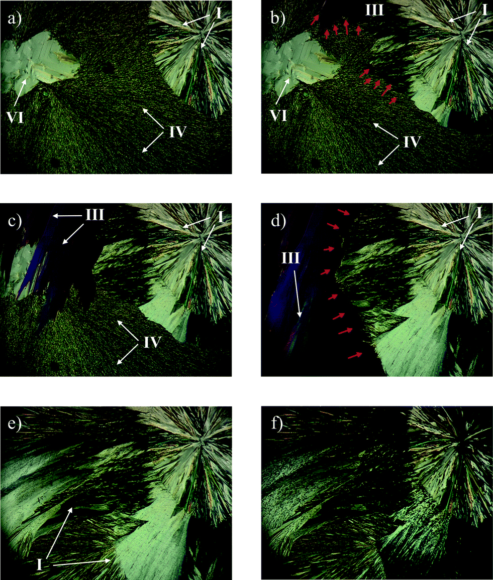 | ||
| Fig. 3 Polarized light HSM photomicrographs of a thin film preparation showing the polymorphs IPH I, III, V and VI formed on slow cooling the melt and their phase transitions on heating. a) Sample before heating showing the typical morphology of IPH I (spherulites), IV (mass of fine needles) and VI (homogeneous plate); b) IPH I grows towards IV and III appears at the top of the image (dark blue) indicating the phase transitions IV to I and IV to III starting at about 145 °C (red arrows mark the transition boundary). c) The phase transitions continue (including that of VI to III) until c) IPH V and VI are completely transformed into IPH III and I; e) a further phase transition (155 °C) occurs (IPH III to I) until only IPH I remains; f) IPH I starts to melt at 173 °C. | ||
Additional phase transitions are easily recognized in melt film preparations (between glass slide and cover slip) of IPH. Such films recrystallize on slow cooling to four concomitant forms of IPH, namely form I, III, IV and VI (Fig. 3). The recrystallization process occurs at about 130 °C on cooling and in repeated experiments, different amounts of the individual forms were obtained, ranging from complete coverage of the thin film preparation (IPH III) to only a small portion of a specific crystal form beside others. On reheating such preparations, several phase transitions are observed. The transitions of IPH IV and VI to IPH III occur over the range of 145–155 °C. Additionally during this process, IPH IV and VI is also transformed by adjacent IPH I. However, because the transition rate of the two metastable forms into IPH I is much smaller than that into IPH III, only a relatively small portion of IPH I and a large fraction of IPH III is present in the thin-film samples after the first transition processes are completed at about 155 °C.
The second phase transition process begins with the end of the first phase transition range (about 155 °C), and reflects the transition of IPH III into IPH I. At ca. 165 °C the entire thin-film is converted into the high temperature form IPH I, which then melts at 173 °C. When such hot-stage experiments are performed with preparations produced by fusing spots of IPH powder on a glass slide coated with silicon oil without a cover slip, additional thermal events can be observed (Fig. 4). The advantage of this preparation technique compared to a coherent melt film preparation is the formation of isolated droplets, in which a single metastable form may nucleate and grow. If such isolated areas of metastable forms are not seeded or are in contact with more stable phases, no solid–solid phase transition is induced and they may survive until their melting point is reached. In fact, the individual melt droplets of IPH crystallize to different polymorphic forms, similar to that described above for thin film preparations (Fig. 3). However, IPH IV forms dendrites and needles (Fig. 4a), which do not quickly transform to IPH III on heating because they are largely isolated from this more stable form. Therefore, it was possible to determine the homogeneous melting point of IPH IV at 145 °C (Fig. 4b) although islands of IPH III and VI are present in the close surrounding. On further heating the inhomogeneous phase transition of IPH VI into IPH III is observed around 155 °C (Fig. 4c–d). Owing to the lack of IPH I seeds, no further transitions occur and these preparations and the melting of phase pure IPH III can be observed at 163 °C.
 | ||
| Fig. 4 Microphotographs of islands of IPH crystallized on silicon oil coated glass slide on heating. a) Typical appearance of IPH IV (dendrites) beside droplets recrystallized to IPH III; b) concomitantly recrystallized IPH III, IV and VI; c) inhomogeneous melting of IPH VI to III at 145 °C (red arrows in the enlarged insert indicate the recrystallization of III in melted areas); d) completion of the phase transition VI to III at 155 °C; e–f) end of melting process of IPH III at about 163 °C. | ||
A third alternative melt crystallization condition was applied by quench-cooling melted samples of IPH to 25 °C. The supercooled melt (or glass) resulting from this fast cooling process recrystallizes between 60 and 70 °C on warming and the obtained crystals exclusively consist of IPH I, melting at 172 °C.
DSC analysis and estimation of the thermodynamic stability
The thermal behaviour of the IPH forms observed with HSM was additionally verified and complemented by DSC experiments. A series of heating and cooling experiments were conducted, mostly by starting with powdered IPH V (Fig. 6). DSC traces of other isolated IPH forms are shown in Fig. S1 to S3 of the ESI.† Reliably measured thermochemical data are summarised in Table 1.In the first heating cycle (Fig. 5), a weak endothermic peak with an onset temperature of 123 °C indicates the phase transition of IPH V into III. At 163 °C the inhomogeneous melting process (melting of III and simultaneous crystallization of IPH I) of IPH III to I is recorded as endo/exo process. The final thermal event in the heating cycle is caused by the melting of IPH I at 172 °C. The subsequent cooling cycle shows the concomitant crystallization of IPH I, III, IV and VI from the melt. This crystallization process occurs reproducibly between 80 and 95 °C (see also cooling cycle 2 and 3 in Fig. 5). Reheating the crystallized melt shows a weak endothermic event around 157 °C followed by an exothermic signal, well visible in the third heating cycle of Fig. 5. This thermal event comprises most likely the transformation and inhomogeneous melting of untransformed traces of IPH VI to IPH III, suggesting that the lower melting IPH IV (145 °C, see HSM experiments) underwent a solid–solid transformation to IPH III already at lower temperatures. We assume that the transformation of IV into III is energetically very weak and occurs over a broad temperature range, which may be why the transition it is not observable in the DSC signal.
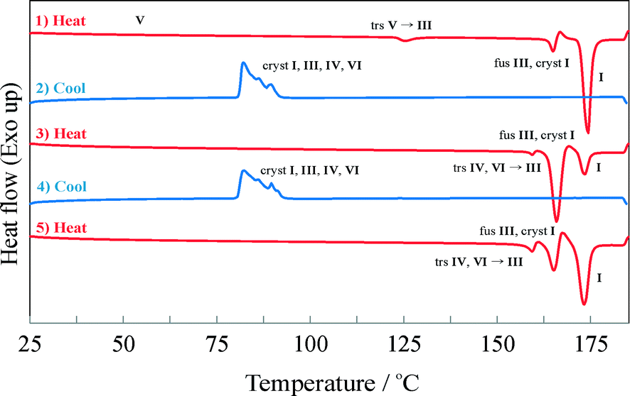 | ||
| Fig. 5 DSC traces of successive heating/cooling runs beginning with IPH V. The initial trace shows the first phase transition (trs) from V to III followed by the inhomogeneous melting (fus III, cryst I) of IPH III into I, and finally melting (fus) endotherm of IPH I. On cooling, IPH I, III, IV and VI recrystallize (cryst) concomitantly between about 90 and 80 °C. In the second heating cycle the phase transitions of IV and VI to III are indicated by a weak endotherm around 157 °C followed by the imhomogeneous melting of IPH III to I and the melting of IPH I. The following cool/heat cycle (trace 4 and 5) confirm the reproducibility of the thermal events. The heating rate is 15 K min−1. | ||
The DSC results are largely consistent with the HSM observations. However, neither technique allowed the determination of the melting point of IPH V, because of the fast transition to IPH III at about 123 °C. However, it was possible to determine the melting temperatures of IPH II (165 °C) and III (162–163 °C) with both HSM and DSC (see. Fig. S2 and S3 of the ESI†).
As shown in Fig. 6, the supercooled melt resulting from crash cooling of the melt shows a broad recrystallization exotherm at approximately 65 °C upon reheating. Subsequently only the melting of IPH I is recorded, confirming the HSM observations (see above).
 | ||
| Fig. 6 DSC heating run of the super-cooled IPH melt. At 65 °C, a broad exothermic peak is observed, indicating the crystallization of IPH I, followed by the melting endotherm of IPH I. | ||
For a compound with six polymorphs (n = 6) we can calculate fifteen polymorph pairs either being monotropically or enantiotropically related.37 The available thermal data allow only a very limited estimation of the thermodynamic relationships of some of the forms in this complex polymorphic system. IPH I is the form with the highest melting point and lowest density. Therefore, we can assume that this form shows the highest entropy and a low thermodynamic stability (high free energy) at 0 K. From this, it can be deduced that IPH I is enantiotropically related to most, if not to all, of the other forms. IPH V shows the highest density, and our data suggest that this polymorph is the thermodynamically stable form at room temperature. The observed endothermic transition (DSC) of IPH V into IPH III is a clear indication of the enantiotropic relationship between these two forms (heat-of-transition rule38). This fact implies the existence of a temperature window above room temperature where IPH III is thermodynamically more stable than IPH I and V. Moreover, IPH II is the form with the second highest melting point and its density is slightly higher than that of IPH III, suggesting a higher stability of IPH II with respect to IPH III, at least in the higher temperature region. This finally means that there are three temperature regions, with different forms being the thermodynamic most stable form: IPH V at and below room temperature, IPH II in a temperature window above room temperature and below the melting point, and finally IPH I in a limited temperature range right below its melting point. Consequently, IPH III, IV and VI are metastable in the entire temperature range. However, as already mentioned, the available thermochemical data do not allow a save estimation of the thermodynamic stabilities of the IPH forms and more efforts are needed to resolve the energetic features this polymorphic system. Nevertheless, it should be stressed that the IPH forms exhibit a high kinetic stability, which is indicated by the observation that I, II and III did not transform to the room temperature stable form V even after a storage period of one year.
Crystal structures of IPH I–VI
Crystal structure of IPH I
The asymmetric unit of IPH I consists of four molecules, denoted A–D (Fig. 7). These are pairwise hydrogen bonded to one another (A + B and C + D) via N1–H1⋯O1C6 interactions which result in two discrete dimers whose graph set symbol39,40 is R22(8). Form I is the only IPH polymorph in which the position of the amide H atom with respect to the carbonyl group is syn. (Note: the IPH from the reaction always comes out with the (E)-geometry about the CN double bond and we never observed the (Z)-isomer).
 | ||
| Fig. 7 Asymmetric units and atom numbering schemes of I–VI. Displacement ellipsoids are drawn at the 50% probability level and H atoms are shown as small spheres of arbitrary size. In the case if I, H atoms not involved in hydrogen bonding are omitted for clarity. | ||
Crystal structure of IPH II
The asymmetric unit of IPH II contains two molecules, denoted A and B (Fig. 7), which form two distinct hydrogen-bonded structures. Molecules of type A are linked into an infinite chain via (amide) N1–H1⋯O1 hydrogen bonds. This chain propagates parallel to the c-axis and has the graph set symbol C(4). By contrast, the hydrazide hydrogen and pyridine nitrogen of molecule B are employed in an N1–H1⋯N2 interaction which results in a dimer with a central R22(14) ring. The A- and B-type molecules are not hydrogen bonded to one another. IPH II is the only polymorph of IPH in which the pyridine nitrogen atom is engaged in hydrogen bonding.Crystal structures of IPH III–VI
The structure of each of these three polymorphs contains just one independent molecule (Fig. 7). They all exhibit hydrogen bonded chains which are analogous to the C(4) chain formed by the A-type molecules of II.Crystal packing relationships
The results discussed below were obtained from pairwise crystal structure comparisons for the group comprising the IPH forms I–VI and the crystal structures of 1-(2-aminobenzoylhydrazono)-1-phenylethane41 (AHE) and N′-[(E)-1-phenylethylidene]benzohydrazide42 (PEH), which are two close analogues of IPH. All IPH polymorphs except I contain an N–H⋯OC-bonded chain of the C(4) type (Fig. 8a) possessing glide symmetry. This chain can occur in three distinct geometries (denoted X, Y and Z) (Fig. 8b), which differ from one another in the relative orientation of their molecules with respect to the glide plane (Fig. 8c). The chain type X is present in III, V, AHE and PEH. Additionally, the stacking mode of the X chains along the short molecular dimension and normal to the chain translation vector is the same in these four crystal structures so that they have two-dimensional supramolecular construct (SC),35 denoted X1, in common (Fig. 9). The two-dimensional packing similarity in this subset is associated with three matching unit cell parameters (two axis at a 90° angle) (Table S2, ESI†). Geometric differences between the X1 units of V and PEH are very low. Larger but still remarkably low (x18 ≤ 5.0) dissimilarity indices are obtained for comparisons which involve AHE, in particular if the presence of an additional NH2 ring substituent in the latter structure is taken into account.
 | ||
| Fig. 8 a) Schematic representation of the N–H⋯OC-bonded C(4) chain motif (IPH: R1 = 4-pyridyl, R2 = phenyl) and b) tree diagram according to ref. 45 which summarises packing relationships between crystal structures; c) N–H⋯OC bonded chains of the geometry types X (III), Y (IV) and Z (VI), viewed along their respective translation vector (dotted lines indicate an axial glide plane with a glide vector of 1/2 of the lattice vector normal to the projection plane); d) centrosymmetric dimer units present in the IPH polymorphs II (molecule B) and VI [symmetry operations: (i) 1 − x, − y, 1 − z and (ii) 1 − x, − y, − z]. | ||
 | ||
| Fig. 9 Two-dimensional packing similarity between the crystal structures of PEH and AHE and in the IPH polymorphs III and V, based on the stacking of N–H⋯OC-bonded chains of type X. Each structure is viewed perpendicular (top) and parallel (bottom) to the translation vector of its H-bonded chains. In each diagram one instance of X1 (orange) or X2 (orange + blue) is highlighted and for each chain the direction of translation is indicated by an arrow in the upper row of diagrams. All hydrogen atoms except those involved in hydrogen bonding are omitted for clarity. | ||
By contrast, high dissimilarity indices (x18 = 12.6–14.2) are obtained for all the X1 comparisons involving IPH III, indicating significant differences both in the geometry of the individual H-bonded chains and in their stacking mode. These differences (illustrated in the top row of diagrams in Fig. 9) also result in relatively large deviations in the lattice parameters associated with X1 (IPH V, PEH and AHE: 5.55–5.78 and 8.22–8.59 Å vs.III: 6.35 and 7.66 Å).
The structures of IPH V and PEH have a bilayer unit in common (denoted X2). It consists of two X1 stacks which are related to one another either by crystallographic (IPH V) or by local (PEH) inversion symmetry. In the upper four packing diagrams of Fig. 9, individual X1 units are represented by a single N–H⋯OC-bonded chain and differences between the X1 packing sequences of the four structures are highlighted by arrows indicating the direction of intermolecular H→O interactions. Neighbouring X2 bilayers of IPH V are related to one another by a 21 screw operation about an axis parallel to the stacking vector of the X1 stacks (b axis), while neighbouring X2 bilayers of PEH are related by a two-fold screw operation about an axis which lies perpendicular to both the stacking vector of X1 and the translation vector of the H-bonded chains (crystallographic c axis). The X2 units of IPH V and PEH display only small geometrical differences (x18 = 2.2).
In the polymorphs II and IV, the N–H⋯OC-bonded chains possess a Y-type geometry (Fig. 8; II: A-type molecules only, see above). Neighbouring Y chains related by translation are stacked in the same fashion in IPH II and IV, resulting in a mutual two-dimensional SC Y1 (Fig. 10). The Y1 stacks of II lie in ac planes and alternate with stacks of dimers formed by B-type molecules. In IV, consecutive Y1 stacks (in ac planes) are related by an inversion operation. As a consequence of these relationships, the unit cells of II and IV correspond with respect to a, c and β (see Table S4 in ESI†).
 | ||
| Fig. 10 Two-dimensional similar packing of molecules, based on Y-type N–H⋯OC-bonded chains, in the IPH polymorphs II (molecule type A only) and IV. Each structure is viewed parallel (left) and perpendicular (right) to the direction of translation of its H-bonded chains (indicated by an arrow), with one instance of the SC Y1 highlighted (orange). All hydrogen atoms, except for those involved in hydrogen bonding, are omitted for clarity. | ||
However, it should be noted that the Y1 stack geometries of II and IV also show significant differences, indicated by the x18 dissimilarity index of 15.0, whereas the corresponding x8 index of 8.7 is substantially lower. These values indicate that the common packing arrangement of II and IV is best maintained within the central section of the Y chains, while the larger differences arise primarily from the packing of the aromatic rings, see Fig. 10. An overview of the geometry relationships arising from the C(4) chain motif is given in Fig. 8b, which also includes the geometry type Z found solely in the IPH polymorph VI (Fig. 8c). Another noteworthy packing similarity involves the centrosymmetic dimer unit depicted in Fig. 7d which contains extensive van der Waals contacts and is present in II (molecule B) and VI (x18 = 8.2).
Conclusions
Polymorphism, although a well-known phenomenon, still requires a significant consideration during pharmaceutical production owing to its unexpected or occasional appearance. IPH represents an outstanding example of polymorphism with six polymorphs having been identified, characterised and described in the present study including their crystal structures. This was possible as a result of the high kinetic stability of the metastable forms (IPH I, II, III, IV, VI). Hot stage microscopy proved again to be a powerful and versatile tool in the analysis of meltable polymorphic substances. The functionality of HSM includes melting point analysis, the qualitative description of thermal phase transitions as well as the controlled production of single crystals for single crystal structure analysis, as demonstrated in the present study and elsewhere.43,44 There is a competition between a dominating H-bonded catemer motif (present in forms II–VI) and two distinct dimer motifs (forms I and [catemer + dimer]: II) in the IPH system. Further analysis of this compound may yield even more isolatable polymorphs, and it could become contender for the polymorphic crystal structure record.Acknowledgements
We would like to thank the Molecular Sciences Institute for infrastructure support and the National Research Foundation (grant numbers: SFH1207163079 and 85964) for funding throughout the duration of this research. The National Research Foundation National Equipment Programme (UID: 78572) is thanked for financing the purchase of the single-crystal diffractometer. AL thanks the University of the Witwatersrand Friedel Sellschop Grant. Additional acknowledgement is given to Prof M. A. Fernandes for crystallographic assistance; Prof D. G. Billing for powder patterns; and Mr. M. Smith for RAMAN spectra collection.References
- W. Cabri, P. Ghetti, G. Pozzi and M. Alpegiani, Org. Process Res. Dev., 2006, 11, 64–72 CrossRef.
- A. J. Aguiar, J. Krc, A. W. Kinkel and J. C. Samyn, J. Pharm. Sci., 1967, 56, 847–853 CrossRef CAS PubMed.
- A. J. Aguiar and J. E. Zelmer, J. Pharm. Sci., 1969, 58, 983–987 CrossRef CAS PubMed.
- T. Ueto, N. Takata, N. Muroyama, A. Nedu, A. Sasaki, S. Tanida and K. Terada, Cryst. Growth Des., 2011, 12, 485–494 Search PubMed.
- R. J. Craven and R. W. Lencki, Chem. Rev., 2013, 113, 7402–7420 CrossRef CAS PubMed.
- H. G. Brittain, J. Pharm. Sci., 2002, 91, 1573–1580 CrossRef CAS PubMed.
- S. L. Morissette, Ö. Almarsson, M. L. Peterson, J. F. Remenar, M. J. Read, A. V. Lemmo, S. Ellis, M. J. Cima and C. R. Gardner, Adv. Drug Delivery Rev., 2004, 56, 275–300 CrossRef CAS PubMed.
- J. D. Dunitz and J. Bernstein, Acc. Chem. Res., 1995, 28, 193–200 CrossRef CAS.
- A. J. Cruz-Cabeza and J. Bernstein, Chem. Rev., 2013, 114, 2170–2191 CrossRef PubMed.
- A. Y. Lee, D. Erdemir and A. S. Myerson, Annu. Rev. Chem. Biomol. Eng., 2011, 2, 259–280 CrossRef CAS PubMed.
- R. J. Davey, N. Blagden, G. D. Potts and R. Docherty, J. Am. Chem. Soc., 1997, 119, 1767–1772 CrossRef CAS.
- A. Nangia, Acc. Chem. Res., 2008, 41, 595–604 CrossRef CAS PubMed.
- C. Rustichelli, G. Gamberini, V. Ferioli, M. C. Gamberini, R. Ficarra and S. Tommasini, J. Pharm. Biomed. Anal., 2000, 23, 41–54 CrossRef CAS.
- A. Grunenberg, J. O. Henck and H. W. Siesler, Int. J. Pharm., 1996, 129, 147–158 CrossRef CAS.
- B. Rodriguez-Spong, C. P. Price, A. Jayasankar, A. J. Matzger and N. Rodriguez-Hornedo, Adv. Drug Delivery Rev., 2004, 56, 241–274 CrossRef CAS PubMed.
- H. Meyer and J. Mally, Monatsh. Chem., 1912, 33, 393–414 CrossRef CAS.
- H. H. Fox and J. T. Gibas, J. Org. Chem., 1953, 18, 983–989 CrossRef CAS.
- M. Malhotra, S. Sharma and A. Deep, Med. Chem. Res., 2012, 21, 1237–1244 CrossRef CAS.
- C. G. Wermuth, C. R. Ganellin, P. Lindberg and L. A. Mitscher, Pure Appl. Chem., 1998, 70, 1129 CrossRef CAS.
- M. Malhotra, G. Sharma and A. Deep, Acta Pol. Pharm., 2012, 69, 637–644 CAS.
- M. Malhotra, V. Monga, S. Sharma, J. Jain, A. Samad, J. Stables and A. Deep, Med. Chem. Res., 2012, 21, 2145–2152 CrossRef CAS.
- T. Steiner, Angew. Chem., Int. Ed., 2002, 41, 48–76 CrossRef CAS.
- J.-H. Jiang, J. Chen, J. Yang and F.-F. Jian, Acta Crystallogr., Sect. E: Struct. Rep. Online, 2009, 65, o3125 CAS.
- N. Zencirci, T. Gelbrich, V. Kahlenberg and U. J. Griesser, Cryst. Growth Des., 2009, 9, 3444–3456 CAS.
- N. Zencirci, T. Gelbrich, D. C. Apperley, R. K. Harris, V. Kahlenberg and U. J. Griesser, Cryst. Growth Des., 2009, 10, 302–313 Search PubMed.
- S. Chen, I. A. Guzei and L. Yu, J. Am. Chem. Soc., 2005, 127, 9881–9885 CrossRef CAS PubMed.
- V. López-Mejías, J. W. Kampf and A. J. Matzger, J. Am. Chem. Soc., 2012, 134, 9872–9875 CrossRef PubMed.
- O. Reany, M. Kapon, M. Botoshansky and E. Keinan, Cryst. Growth Des., 2009, 9, 3661–3670 CAS.
- Bruker, SAINT+, version 6.02 (including XPREP), Bruker AXS Inc., Madison, WI, USA, 1999 Search PubMed.
- L. Farrugia, J. Appl. Crystallogr., 1999, 32, 837–838 CrossRef CAS.
- G. M. Sheldrick, SHELX, release 97-2 (includes SHELXS and SHELXL), University of Göttingen, 1997 Search PubMed.
- L. Farrugia, J. Appl. Crystallogr., 1997, 30, 565 CrossRef CAS.
- A. Spek, J. Appl. Crystallogr., 2003, 36, 7–13 CrossRef CAS.
- H. Putz and K. Brandenburg, Diamond Version. 3.0e - Crystal and Molecular Structure Visualization - Crystal Impact GbR, Kreuzherrenstr. 102, 53227 Bonn, Germany Search PubMed.
- T. Gelbrich and M. B. Hursthouse, CrystEngComm, 2005, 7, 324–336 RSC.
- T. Gelbrich, T. L. Threlfall and M. B. Hursthouse, CrystEngComm, 2012, 14, 5454–5464 RSC.
- D. E. Braun, T. Gelbrich, V. Kahlenberg, R. Tessadri, J. Wieser and U. J. Griesser, J. Pharm. Sci., 2009, 98, 2010–2026 CrossRef CAS PubMed.
- A. Burger and R. Ramberger, Microchim. Acta, 1979, 72, 259–271 CrossRef.
- M. C. Etter, Acc. Chem. Res., 1990, 23, 120 CrossRef CAS.
- J. Bernstein, R. E. Davis, L. Shimoni and N.-L. Chang, Angew. Chem., Int. Ed. Engl., 1995, 34, 1555–1573 CrossRef CAS PubMed.
- M. F. Simeonov, F. Fülöp, R. Sillanpää and K. Pihlaja, J. Org. Chem., 1997, 62, 5089–5095 CrossRef CAS.
- H. K. Fun and S. R. Jebas, Acta Crystallogr., Sect. E: Struct. Rep. Online, 2008, 64, o1255 CAS.
- A. Lemmerer, J. Bernstein, U. J. Griesser, V. Kahlenberg, D. M. Többens, S. H. Lapidus, P. W. Stephens and C. Esterhuysen, Chem. – Eur. J., 2011, 17, 13445–13460 CrossRef CAS PubMed.
- T. Gelbrich, D. E. Braun, A. Ellern and U. J. Griesser, Cryst. Growth Des., 2013, 13, 1206–1217 CAS.
- T. Gelbrich and M. B. Hursthouse, CrystEngComm, 2006, 8, 448–460 RSC.
Footnotes |
| † Electronic supplementary information (ESI) available: Details of the XPac studies, X-ray powder diffraction, RAMAN, FT-IR, NMR, additional DSC traces and further crystallographic tables and data. CCDC 970533–970537 and 1022894. For ESI and crystallographic data in CIF or other electronic format see DOI: 10.1039/c5ce00275c |
| ‡ Dedicated to David J. W. Grant on the 10th anniversary of death (died December 9, 2005 at age 68). |
| This journal is © The Royal Society of Chemistry 2015 |