 Open Access Article
Solid electrolyte interphase in semi-solid flow batteries: a wolf in sheep's clothing†
E.
Ventosa
*ab,
G.
Zampardi
b,
C.
Flox
a,
F.
La Mantia
bc,
W.
Schuhmann
b and
J. R.
Morante
ad
aCatalonia Institute for Energy Research, Jardins de les Dones de Negre, e1, 08930 Sant Adria de Besos, Barcelona, Spain. E-mail: edgar.ventosa@rub.de
bAnalytical Chemistry – Center for Electrochemical Sciences (CES), Ruhr-University Bochum, Universitätsstr. 150, 44780 Bochum, Germany
cEnergiespeicher- und Energiewandlersysteme, Universität Bremen, Wiener Str. 12, 28359 Bremen, Germany
dDepartament d'Electronica, Facultat de Fisica, Universitat de Barcelona, Martí i Franques 1, 08028 Barcelona, Spain
First published on 30th July 2015
Abstract
The formation of the alkyl carbonate-derived solid electrolyte interphase (SEI) enables the use of active materials operating at very cathodic potentials in Li-ion batteries. However, the SEI in semi-solid flow batteries results in a hindered electron transfer between a fluid electrode and the current collector restricting the operating potentials to ca. 0.8 V vs. Li/Li+ for EC-based electrolytes.
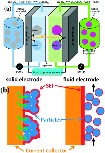
The semi-solid flow battery (SSFB) is a promising energy storage technology that combines the high energy density of Li-ion battery (LIB) materials with the independent scalability of energy and power capabilities of redox flow batteries (RFBs).1–7 The operational principle of SSFB is based on RFB, but employing suspensions containing LIB materials instead of dissolved electroactive species (Fig. 1a). Despite the fact that the chemistry of SSFB relies on the chemistry of well-investigated Li-ion battery materials, the fluid electrodes cannot be assumed to behave as the solid ones. The formation of a stable solid electrolyte interphase (SEI) at the negative electrode of classic LIBs can be considered as a blessing since its electrically insulating character hinders the electron transfer at the surface of the electrode and prevents further decomposition of the electrolyte solution. Only through the formation of a stable SEI, active materials operating at very cathodic potentials are suitable for LIBs, e.g. graphite at 0.1 V vs. Li/Li+. Although the properties of the SEI in SSFBs may be very similar to those of SEI in classic LIBs when using the same electrolyte solution, there is a major difference between the SEI in LIBs and SSFBs (Fig. 1b): namely the location of the SEI. In classic LIBs, the SEI is formed around the “static” solid electrodes, allowing many contact points between particle/particle and particle/current collector to remain mostly “uncovered” for facile electron transport across the entire solid electrode. Thus, the SEI in LIBs is mostly located at the interface between electrode and electrolyte. On the other hand, in SSFBs the active particles are in continuous motion. The contacts for electron transfer between current collector and particles are severed and re-established continuously, which allows the SEI to cover the entire current collector. Thus, the SEI in SSFBs is mostly located between the current collector and the fluid electrode. Once the SEI is formed in SSFBs, the electrons must cross this electrically insulating barrier on their way from the current collector to the active material and vice versa.
 | ||
| Fig. 1 (a) Scheme of a semi-solid flow battery (SSFB). (b) Representations of the SEI of a classic Li-ion battery versus that of a SSFB. | ||
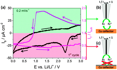
Fast electron transfer kinetics between the current collector and the fluid electrode are necessary for high-performance SSFBs. Scanning electrochemical microscopy (SECM) in the feedback mode provides this type of information, which was previously used for the study of the properties of the SEI in classic Li-ion batteries.8–12Fig. 2a shows the current recorded at the copper current collector (black line) together with the feedback current simultaneously recorded at the tip (red line) during the first cyclic voltammogram at 0.2 mV s−1 in 1 M LiPF6 in EC:DEC. During the experiment the SECM tip was polarized at a constant potential of 3.6 V vs. Li/Li+ and at a constant position at 12 μm from the Cu surface (see ESI† for more details on SECM). The current at the current collector (black line) shows a small peak at 2.3 V vs. Li/Li+, attributed to the reduction of copper oxide, and a small increase in cathodic current below 0.5 V vs. Li/Li+. The signal at the tip (red line) provides information regarding the charge transfer kinetics at the surface of the current collector. In a simplistic view, values of I/Ibulk above unity reveal the occurrence of fast charge transfer at the current collector (Fig. 2b), while values below unity indicate the hindered charge transfer (Fig. 2c). Initially, the value of I/Ibulk was ca. 1.3 and it increased in the cathodic scan due to the increased driving force at the current collector for the regeneration of the mediator. I/Ibulk at the tip reached a value of ca. 1.8 at 1.5 V vs. Li/Li+ and remained stable. The value was expected to remain constant, but it drastically dropped when potentials more cathodic than 1.0 V vs. Li/Li+ were applied to the current collector. I/Ibulk continued decreasing until the end of the cathodic scan at 0.01 V vs. Li/Li+. During the entire anodic scan, the value of I/Ibulk remained at ca. 0.6. In short, I/Ibulk values above unity were recorded during the initial cathodic scan at potentials more anodic than 1.0 V, while I/Ibulk values below unity were obtained for the rest of the measurement. This indicates that the formation of the SEI, previously reported in Li-ion batteries to occur at ca. 1.0–0.8 V vs. Li/Li+ in the first cathodic scan mainly,12–14 turned the surface of the Cu current collector from kinetically active to inactive charge transfer at ca. 0.8 V vs. Li/Li+. In classic LIBs, this loss of activity towards electron transfer at the electrode surface prevents continuous decomposition of the electrolyte solution, which is truly beneficial. However, SSFBs require the electron transfer at the surface of the current collector to occur since the active materials are suspended in the fluid electrode. As a consequence, the Li-ion (de-)insertion in active materials operating below 1.0 V vs. Li/Li+ is expected to be challenging in SSFBs. Therefore, the hindrance of the charge transfer at the surface of the current collector should be considered as a limitation for SSFBs, instead of an advantage.
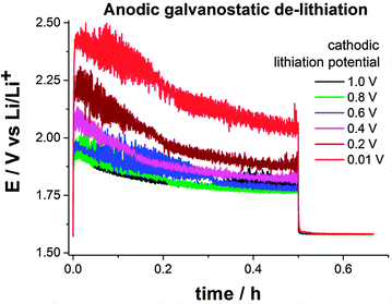
Lithium titaniate (LTO) operates within the electrochemical stability window of carbonate-based electrolyte solutions since the (de-)intercalation potential of LTO is ca. 1.55 V vs. Li/Li+.15,16 Therefore, a SEI is not formed (or only a very thin one) when using LTO as negative electrode material because potentials below 1.0 V vs. Li/Li+ are not required. Nevertheless, a SEI can be intentionally formed during lithiation of LTO when a potentiostatic cathodic pulse below 1.0 V is applied. In a half-cell configuration SSFB (metallic lithium as counter- and reference electrode), a suspension containing 16 wt% of LTO and 1.4 wt% of carbon black in 1 M LiPF6 in EC:DMC was evaluated at a constant flow rate of 3 mL min−1. The LTO in the suspension was fully lithiated potentiostatically at 1.0 V vs. Li/Li+. After that, a galvanostatic anodic pulse for 30 min at +2 mA (0.66 mA cm−2) was applied, followed by 10 min at open circuit potential. The same procedure was applied several times, only changing the potential of the lithiation, which was sequentially lowered from 1.0 to 0.01 V vs. Li/Li+ in intervals of 0.2 V. The SEI formed during the cathodic lithiation acts as electron transfer barrier for (de-)lithiation of the active material, resulting in higher overpotentials in the galvanostatic de-lithiation. The electric resistance introduced by the SEI can be evaluated by comparing the overpotentials during the galvanostatic anodic pulses. Fig. 3 shows the anodic potential/time transients obtained for different potentiostatic lithiation conditions. According to Fig. 2, the charge transfer at the surface of the current collector starts to be hindered at 0.9 V vs. Li/Li+. Therefore, one could expect an increased overpotential in the anodic E–t transient for the lithiation at 0.8 V vs. Li/Li+. Surprisingly, no significant change in the overpotential was observed until a cathodic lithiation potential of 0.4 V vs. Li/Li+ was applied. On the opposite, with respect to the anodic de-lithiation potential recorded at 1.0 V vs. Li/Li+, an additional overpotential of 40 mV, 100 mV and 260 mV were required when the cathodic lithiation was carried out at 0.4 V, 0.2 V and 0.01 V vs. Li/Li+, respectively. Although electron transfer occurs at all cathodic lithiation potential, the anodic overpotential of the de-lithiation increases when lithiation is carried out at potentials below 0.6 V vs. Li/Li+, which is attributed to the formation of a SEI. From SECM measurements, higher overpotentials could be expected when the lithiation is carried out at potentials below 0.8 V vs. Li/Li+. There are two possible explanations for this apparent discrepancy. At operating potentials above 0.4 V vs. Li/Li+ the SEI (I) is not thick and/or stable enough to be the limiting factor or (II) is partially eroded considering the fact that a fluid electrode consisting of a slurry of solid particles flows through the electrode's channel. In any case, electrolyte decomposition starts to occur at ca. 0.9 V vs. Li/Li+. Therefore, operating potentials below 0.8 V vs. Li/Li+ should be avoided in SSFBs when using ethylene carbonate based electrolyte solutions.
The increased charge transfer resistance at the fluid electrode due to the SEI leads to an increased overpotential during (de-)lithiation. Despite the erosion of the SEI, the overpotential appears to be critical when operating below 0.4 V vs. Li/Li+. As a consequence, the lithiation of active materials operating below 0.4 V vs. Li/Li+ appears to be challenging. For example, the lithiation of graphite occurs at ca. 0.1 V vs. Li/Li+. If a potential of 0.01 V vs. Li/Li+ is applied to drive the lithiation process, an overpotential of 260 mV will be induced by the SEI. As a result, the fluid electrode will be polarized only to 0.27 V vs. Li/Li+, which is not sufficient for the lithiation to occur at graphite. On the other hand, the use of active materials operating between 0.8 V and 0.4 V vs. Li/Li+ appears to be possible because of the erosion of the SEI by the slurry in flowing conditions. Although lithiation of active materials in the range 0.8–0.4 V vs. Li/Li+ is possible, operating in this potential range will probably lead to the consumption of the electrolyte solution over time.
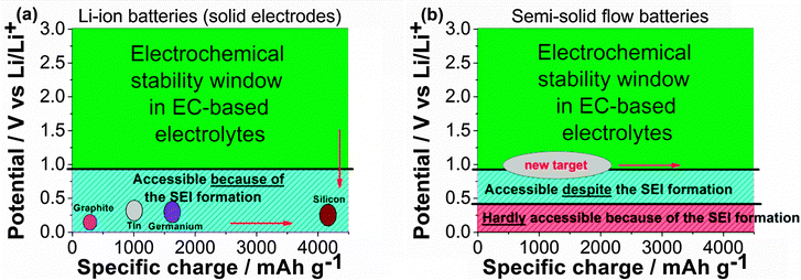
The classic schemes (Fig. 4) employed to represent the energy density of a LIB active material in EC-based electrolytes (operating potential vs. specific charge) should be reconsidered for SSFBs. For LIBs, negative electrode materials located at the right bottom corner of the scheme are highly desired (Fig. 4a), which is possible thanks to the electrically insulating character of the SEI. However, the right bottom corner appears to be inaccessible for SSFBs since the lithiation of materials below 0.4 V vs. Li/Li+ is very challenging. Potentials between 0.8–0.4 V vs. Li/Li+ are not sustainable for long term operation either. Instead, materials operating between 1.2 V and 0.8 V vs. Li/Li+ should be targeted for SSFBs. Progress on high energy SSFBs will require either (1) the search and development of novel high energy materials operating above 0.8 V vs. Li/Li+, or (2) the implementation of electrolyte solvents with a higher cathodic stability that enables the use of classic negative electrode materials.
The surface of a copper current collector turns from kinetically active toward charge transfer to inactive when it is polarized at cathodic potentials to 0.8 V vs. Li/Li+ in ethylene carbonate (EC)-based solution. Because the EC-derived SEI covers the current collector due to the dynamic nature of the fluid electrode, the SEI acts as an electron transfer barrier between the current collector and the fluid electrode in SSFBs. Surprisingly, no significant additional overpotentials are observed when lithiating the active material (Li4Ti5O12 in this case) above 0.4 V vs. Li/Li+. Since the SECM measurements indicate that the hindrance of charge transfer at the surface of the Cu current collector already starts at 0.8 V vs. Li/Li+, either (I) the SEI is too thin and/or unstable or (II) the erosion of the soft SEI film by the flowing particles occurs. On the other hand, an increase in the overpotentials of 100 mV and 260 mV is observed when polarizing the electrode at 0.2 V and 0.01 V vs. Li/Li+, respectively. As a consequence of the overpotentials induced by the electrically insulating SEI, the lithiation of active materials operating below 0.4 V vs. Li/Li+ becomes very challenging. A stable SEI formed on the current collector, which is necessary for long-lasting SSFB, will impede the use of materials operating at very cathodic potentials.
The electrically insulating character of the SEI turns from a beneficial feature in classic LIBs to a detrimental one in SSFBs. Although our results were obtained in EC-based electrolyte, they revealed an important dilemma. The SEI must be electrically insulating to electrically passivate the surface and avoid further decomposition. Without this feature, operating beyond the stability window will not be possible. In the case of SSFBs, an electrically insulating SEI will hinder the electron transfer between current collector and active material. A non-electrically insulating SEI will not prevent the electrolyte decomposition and the potentials beyond the SEI formation will not be accessible. Either way, operating outside the stability window of the electrolyte solutions seems not to be possible in SSFBs. Therefore, the enhancement of the energy density in SSFBs requires either the search and development of novel active materials operating at 1.2–0.8 V vs. Li/Li+ or the replacement of carbonate-based electrolyte solution by others which are more stable at very cathodic potentials such as some ionic liquids. Until now, materials operating at 1.2–0.8 V vs. Li/Li+ were of little interest for the battery community due to their lower energy density. Now, materials such as Sb, ZnSb, Bi, back phosphorous or metal phosphides (e.g. NiP2), operating above 0.5 V vs. Li/Li+,17 may regain the attention of the battery community for the next generation of SSFBs.
The research leading to these results has received funding from the European Union Seventh Framework Programme (FP7/2007–2013) under grant agreement no. 608621. European Regional Development Funds (ERDF—FEDER Programa Competitivitat de Catalunya 2007–2013) are also acknowledged.
Notes and references
- M. Duduta, B. Y. Ho, V. C. Wood, P. Limthongkul, V. E. Brunini, W. C. Carter and Y.-M. Chiang, Adv. Energy Mater., 2011, 1, 511–516 CrossRef CAS PubMed.
- S. Hamelet, T. Tzedakis, J.-B. Leriche, S. Sailler, D. Larcher, P.-L. Taberna, P. Simon and J.-M. Tarascon, J. Electrochem. Soc., 2012, 159, A1360–A1367 CrossRef CAS PubMed.
- Y. Yang, G. Zheng and Y. Cui, Energy Environ. Sci., 2013, 6, 1552–1558 CAS.
- S. Hamelet, D. Larcher, L. Dupont and J.-M. Tarascon, J. Electrochem. Soc., 2013, 160, A516–A520 CrossRef CAS PubMed.
- F. Y. Fan, W. H. Woodford, Z. Li, N. Baram, K. C. Smith, A. Helal, G. H. McKinley, W. C. Carter and Y.-M. Chiang, Nano Lett., 2014, 14, 2210–2218 CrossRef CAS PubMed.
- E. Ventosa, M. Skoumal, F. J. Vazquez, C. Flox, J. Arbiol and J. R. Morante, ChemSusChem, 2015, 8, 1737 CrossRef CAS PubMed.
- E. Ventosa, D. Buchholz, S. Klink, C. Flox, L. G. Chagas, C. Vaalma, W. Schuhmann, S. Passerini and J. R. Morante, Chem. Commun., 2015, 51, 7298–7301 RSC.
- G. Zampardi, E. Ventosa, F. La Mantia and W. Schuhmann, Chem. Commun., 2013, 49, 9347 RSC.
- H. Bülter, F. Peters, J. Schwenzel and G. Wittstock, Angew. Chem., Int. Ed., 2014, 53, 10531 CrossRef PubMed.
- G. Zampardi, E. Ventosa, F. La Mantia and W. Schuhmann, Electroanalysis, 2015, 27, 1017 CrossRef CAS PubMed.
- G. Zampardi, S. Klink, V. Kuznetsov, T. Erichsen, A. Maljusch, F. La Mantia, W. Schuhmann and E. Ventosa, ChemElectroChem, 2015 DOI:10.1002/celc.201500085.
- G. Zampardi, F. La Mantia and W. Schuhmann, RSC Adv., 2015, 5, 31166 RSC.
- F. La Mantia and P. Novak, Electrochem. Solid-State Lett., 2008, 11, A84 CrossRef CAS PubMed.
- P. Novák, F. Joho, R. Imhof, J. C. Panitz and O. Haas, J. Power Sources, 1999, 81, 121 Search PubMed.
- Z. Chen, I. Belharouak, Y.-K. Sun and K. Amine, Adv. Funct. Mater., 2013, 23, 959 CrossRef CAS PubMed.
- M. Fehse and E. Ventosa, ChemPlusChem, 2015, 80, 785 CrossRef CAS PubMed.
- C.-M. Park, J.-H. Kim, H. Kim and H.-J. Sohn, Chem. Soc. Rev., 2010, 39, 3115 RSC.
Footnote |
| † Electronic supplementary information (ESI) available. See DOI: 10.1039/c5cc04767f |
| This journal is © The Royal Society of Chemistry 2015 |


![[thin space (1/6-em)]](https://www.rsc.org/images/entities/char_2009.gif) :
:
