 Open Access Article
Magnetic field assisted programming of particle shapes and patterns†
Wenwen
Xu
,
Yuyu
Yao
,
John S.
Klassen
and
Michael J.
Serpe
*
Department of Chemistry, University of Alberta, Edmonton, Alberta T6G 2G2, Canada. E-mail: michael.serpe@ualberta.ca
First published on 10th August 2015
Abstract
Anisotropic particles have generated an enormous amount of research interest due to their applications for drug delivery, electronic displays and as micromotors. However, up till now, there is no single protocol capable of generating particles of “patchy” composition with a variety of well-defined and predictable shapes. To address this, in this submission we dispersed magnetic nanoparticles (MNPs) in a non-magnetic fluid containing monomer and crosslinker. This solution was added to the surface of Teflon, which was submerged in the solvent 2,2,4-trimethylpentane. Under these conditions a round, stable droplet was formed on the Teflon. Upon exposure to a permanent magnet, the MNPs self-assembled into clusters with a variety shapes and sizes. The shape and size of the clusters depended on the magnetic field strength, which we controlled by systematically varying the distance between the magnet and the droplet. Interestingly, the shape of the liquid droplet was also influenced by the magnetic field. Upon polymerization, the MNP patterns and the droplet shape was preserved. We also show that very complex MNP patterns and particle shapes could be generated by controlling the distance between the drop and both a magnet above and below the droplet. In this case, the resulting patterns depended on whether the magnets were attracting or repelling each other, which was capable of changing the field lines that the MNPs align with. Overall, this approach is capable of generating particles with predictable MNP patterns and particle shapes without the use of any templates or complex synthetic steps. Furthermore, by using a sprayer (or similar approaches, e.g., ink jet printing) this technique can be easily scaled up to produce many complex anisotropic particles in a short amount of time.
Introduction
The fabrication of particles with various and controllable shapes, and/or localized chemistry differences is of extreme interest for a variety of applications.1,2 This has been driven by their ability to be used for drug delivery,3 electronic paper,4,5 micromotors,6 and bar coding technology.7 There are several methods proposed for anisotropic particle synthesis; the use of Pickering emulsions is one example.8,9 Specifically, Granick and coworkers,10,11 adsorbed particles at the interface of wax and water, one half of the particle was shielded from the water (due to its attachment to the wax) while the other half remained exposed to the water, which allows for its easy chemical modification independent of the other half. One downfall of this approach is the fact that particles can be detached from the wax during the functionalization, leading to homogenous particle modification, lowering the yield of the asymmetrically modified (Janus) particles. Another approach that is widely used for generating Janus particles is to use microfluidic devices.5,12 However, this method is not universal, and can be cumbersome to optimize to yield the desired particles. For example, flow rate,13 microchannel chemistry,14,15 and microchannel shape16 have to be carefully tuned and optimized to make specific particles. Yet another way to make Janus particles is via block copolymer self-assembly.17 However, solvent selection for phase separation, the requirement for precisely defined molecular composition, and very carefully controlled environments (temperature, humidity, etc.) makes this method tedious to implement.18 While generating basic Janus particles can be cumbersome, the complexity is increased if patches of controlled and defined sizes are required (Janus balance). Controlling these parameters is very important for directing the assembly and attachment of anisotropic particles.19,20The generation of non-spherical Janus particles is another very interesting area because it can yield self-assembled structures with much more complex architectures not available with spheres.21 This is especially challenging due to the fact that most cases obtained spherical Janus particles which offer the lowest surface-to-volume ratio and minimizes the interfacial energy. While this is the case, such particles have been realized. For example, Müller's group synthesized triblock copolymer to yield disc/sheet like Janus particles.22 By asymmetric wet-etching at the Pickering emulsion interface, Yang's group also fabricated non-spherical silica Janus particles.23 However, generally speaking, those methods above are complicated. Therefore, simpler and more efficient methods are highly desirable to generate non-spherical Janus particles.
To address the above needs, in this paper, we developed a new method for anisotropic particle fabrication, which is simple, effective and versatile. This approach utilizes interfacial polymerization of a monomer/crosslinker solution that has magnetic nanoparticles (MNPs) dissolved. By using magnetic fields, and modulation of their strength and the magnetic field line directions, we were able to generate very complex anisotropic particles with well-defined shapes and conformations. These particles not only offer a diverse range of flexibility when it comes to structural and compositional diversity, but they can find utility as building blocks for microactuators in the pharmaceutical industry for cellular manipulation.24,25 We point out that this approach can be used to synthesize complex particles much smaller than what is presented here by simply depositing smaller volumes of liquid on the teflon. Furthermore, the same techniques that can be used to make smaller particles can also be used to make multiple particles in very short amounts of time; e.g., nebulization or ink jet printing.
Experimental
Materials
2-Hydroxylethylmethacrylate (HEMA) (≥97%), poly(ethylene glycol) diacrylate (PEGDA) (Mn = 700), 2,2,4-trimethylpentane (TMP) (≥99%), ammonium persulfate (APS) (≥98%), N,N,N′,N′-tetramethylethylenediamine (TEMED) (≥99%) as well as Fe(II, III) oxide nanoparticles (50 nm–100 nm diameter) with no surface modification was purchased from Sigma Aldrich (Oakville, Ontario). Ultra high-pull Neodymium-Iron-Boron (NdFeB) magnets (5 × 5 × 1 cm) were purchased from McMaster-Carr Company (Elmhurst, IL). Deionized water (DI water) with a resistivity of 18.2 MΩ cm was used and obtained from a Milli-Q Plus system (Millipore Co., Billerica, MA). Polyetrafluoroethylene (PTFE) was provided by Johnston Industrial Plastics (Edmonton, Alberta).Preparation of anisotropic particles
Fe(II, III) oxide magnetite MNPs (0.37 M), 2-hydroxylethylmethacrylate (HEMA) (3.52 M), and poly(ethylene glycol) diacrylate (PEGDA) (0.23 M) aqueous solution was used as the “pre-gel” solution. Aqueous solutions of the initiator ammonium persulfate (APS) (0.44 M) and accelerator N,N,N′,N′-tetramethylethylenediamine (TEMED) (0.67 M) were also used. 10 μL of the APS solution and 10 μL of the TEMED solution were added to 0.1 mL of the pre-gel solution and mixed, and 5 μL aliquots (in most cases) manually added to the PTFE–TMP interface. The external magnetic field was applied by custom-build magnetic stage where two NdFeB magnets were fixed above and below the Petri dish, with positioning screws to accurately and precisely control the distance between the Petri dish and the magnets. The polymerization was allowed to proceed for 1 h before the particles were collected. The mechanism of free-radical polymerization accelerated by TEMED has been studied in detail previously.26 Briefly, TEMED reacts with APS through redox reaction, which produces free radicals, which can initiate polymerization. Thermal gravimetric analysis (TGA) was performed on the resultant particles to determine how much of the particle mass could be attributed to MNPs, and the data are shown in ESI.† From the data, we can determine that the MNPs account for ∼6% (w/w) of the particle mass.Instrumentation
Photographs of the particles were obtained using a Nikon camera equipped with a 105 mm Nikon macrolens (Nikon, Ontario, Canada). Optical microscopy (Olympus IX-70 Melville, New York, USA)) was used to image smaller particle. Contact angle was measured using an automated goniometer with drop image Advanced V2.4 software from rame-hart Instrument Co. (New Jersey, USA). Magnetic measurements of the purchased MNPs were performed using a Quantum Design 9T-PPMS magnetometer with fields up to 1 T at room temperature. TGA was performed using a Perkin Elmer Pyris TGA1 under a nitrogen atmosphere, heating from 25.00 °C to 600.00 °C at scan rate 10.00 °C min−1.Results and discussion
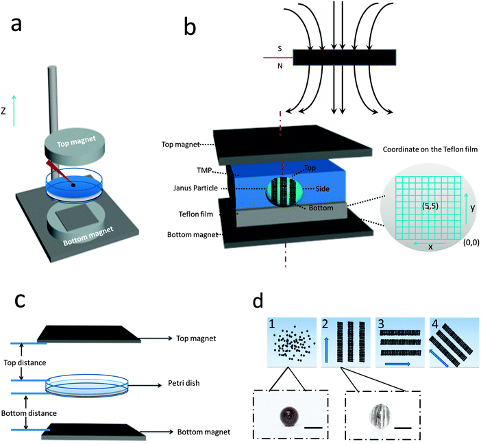
Patterned particles were synthesized by suspending Fe(II, III) oxide magnetic nanoparticles (MNPs) (0.37 M) in 2-hydroxylethylmethacrylate (HEMA) (3.52 M), and poly(ethylene glycol) diacrylate (PEGDA) (0.23 M), which was referred to as the “pre-gel” solution (non-magnetic liquid carrier). Aqueous solutions of ammonium persulfate (APS) (0.44 M) as initiator and N,N,N′,N′-tetramethylethylenediamine (TEMED) (0.67 M) as accelerator were made, and were mixed with the pre-gel solution to make particles. In one case, 100 μL of the pre-gel solution was mixed with 10 μL of the APS solution and 10 μL of the TEMED solution. After this solution was shaken for ∼5 s, 5 μL droplets were dispensed via digital pipet onto a piece of Teflon that was submerged in 2,2,4-trimethylpentane (TMP) all in a Petri dish. Under these conditions, the drops formed nearly perfect spheres on the Teflon surface. This was expected from previously published results.27 In this case, in the absence of a magnetic field, the MNPs were randomly distributed in the droplet (and polymerized particle) due to Brownian motion; the resultant particle shape was spherical. However, when an external magnetic field is applied, chain-like structures (clusters) are observed within 1 s, which are locked into place via polymerization (Fig. 1d). MNP assembly on this time scale has been observed previously, and thus was expected.28 Cluster formation has also been observed in magnetorheological fluids, which were extensively studied.29 Although, magnetorheological fluids are typically composed of magnetic particles with micron-size dimensions, while our particles have nano-dimensions. Thus, while the behavior here should be similar to magnetorheological fluids, it is not necessarily the case.Fig. 1(a) shows a schematic of the setup we used to fabricate anisotropic particles with complex structures and shapes. The setup is composed of a stand capable of holding the Petri dish assembly used above, but also allows for control of the distance between the two magnets and the Petri dish. We point out that the holders for two magnets were made of aluminum, which made it extremely strong and stable. Fig. 1(b) shows the simplified side view of our system. It is important to note that the magnetic field is not uniform over the whole magnet area, so for these experiment, it was important to record the position of every drop relative to the magnet. In order to do this, a coordinate system was used as defined in Fig. 1(b). For our experiments, we always made sure to fix the position of the magnets and the coordinate system, such that it was the same from experiment to experiment. For these studies, it was important to consistently define and measure the proximity of the magnets to the particles. This is detailed in Fig. 1(c), which shows the top distance as the distance between the bottom of the top magnet and the top edge of the Petri dish, while the bottom distance is the distance between top of the bottom magnet and the bottom face of the Petri dish. The same Petri dish and Teflon was used for all experiments – the wall thickness of the Petri dish was 2 mm with a depth of 1 cm and diameter is 8.5 cm; the Teflon was 3 mm thick and had a diameter is 8.2 cm. This way of measuring distance was chosen due to its ease and reproducibility; it was also beneficial because it didn't disturb the system. For demonstration purposes, Fig. 1(d) shows how an external magnetic field could be used to manipulate magnetic particles in the droplet. If polymerization of the drops composed of MNPs proceeded in the presence of a magnetic field, by properly positioning the magnet near the Petri dish used for polymerization, the MNPs could align themselves with the magnetic field lines. Furthermore, when there is applied magnetic field, MNPs obtain an induced dipole moment which causes them to self-assemble into chain structures parallel to the external field lines to minimize the free energy of the system.30 To explain how the magnetic field can be used to assemble the MNPs in the pre-gel solution prior to polymerization, the ratio of the magnetic energy to thermal energy as is shown in eqn (1) needs to be considered, which can be expressed as30,31
 | (1) |
 | (2) |
 | (3) |
| χp = μp − 1 | (4) |
![[m with combining right harpoon above (vector)]](https://www.rsc.org/images/entities/char_006d_20d1.gif) : induced magnetic moment;
: induced magnetic moment; ![[H with combining right harpoon above (vector)]](https://www.rsc.org/images/entities/i_char_0048_20d1.gif) : external field strength; χeff: effective susceptibility; μp: relative permeability of MNPs; μs: relative permeability of solvent and it is equal to the vacuum permeability which is a universal constant; χp is the MNPs' susceptibility. In our case, χp for MNPs is 0.38, their diameter is about 50 nm and the maximum field strength for the permanent magnet is 1777 G. Fig. S1(a) in ESI† shows that saturation magnetisation is achieved only when the external field is above 5000 G, which demonstrates that eqn (1) is suitable for our system. Specifically, λ is the ratio of magnetic energy of MNPs compared to MNPs' thermal energy (Brownian motion). Therefore, when λ is high, the magnetic energy dominates thermal energy and the chain structure forms. According to the above equations, using the above parameters, λ in our system is ∼31, indicating that magnetic forces play a dominant role over thermal fluctuation which can make the particles self- assemble into stable chain clusters. Therefore, the role of the external field is to align MNP chains with the external field, assisting stacking of chains along the axis of the field and then draw them towards the ends of the permanent magnets where the magnetic field gradient is the steepest. The magnet movement and relative positions, and the dipole forces between MNPs can allow the formation of different patterns and even change the shape of the droplet, which we will talk about in detail later.
: external field strength; χeff: effective susceptibility; μp: relative permeability of MNPs; μs: relative permeability of solvent and it is equal to the vacuum permeability which is a universal constant; χp is the MNPs' susceptibility. In our case, χp for MNPs is 0.38, their diameter is about 50 nm and the maximum field strength for the permanent magnet is 1777 G. Fig. S1(a) in ESI† shows that saturation magnetisation is achieved only when the external field is above 5000 G, which demonstrates that eqn (1) is suitable for our system. Specifically, λ is the ratio of magnetic energy of MNPs compared to MNPs' thermal energy (Brownian motion). Therefore, when λ is high, the magnetic energy dominates thermal energy and the chain structure forms. According to the above equations, using the above parameters, λ in our system is ∼31, indicating that magnetic forces play a dominant role over thermal fluctuation which can make the particles self- assemble into stable chain clusters. Therefore, the role of the external field is to align MNP chains with the external field, assisting stacking of chains along the axis of the field and then draw them towards the ends of the permanent magnets where the magnetic field gradient is the steepest. The magnet movement and relative positions, and the dipole forces between MNPs can allow the formation of different patterns and even change the shape of the droplet, which we will talk about in detail later.
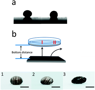
We first investigated the case of a single magnet located below the Petri dish and droplet. The influence of the magnetic field on the droplet shape is shown in Fig. 2(a). As can be seen, well-known magnetowetting phenomena are observed.32 That is, the applied field forces the droplet to flatten (relative to no applied magnetic field) and the contact angle decreases. Furthermore, the magnetic field can cause the MNPs to form patterns, which are easily visible after the particles polymerize, which locks in the MNP structure in the particle. This behavior is clearly shown in the photographs in Fig. 2(b), which shows MNP chains being formed. The alignment of the MNPs in the magnetic field appear similar to what was observed by the Pyun group.33
The reason for the parallel MNP chain structure formation is due to the angular dependence of the dipolar interaction. The external field can cause particles to generate a preferred head-to-tail alignment. Closer examination revealed that the uniform dipole orientation causes a second possibility: side-by-side particles with aligned dipoles resulting in dipole repulsion. This angular dependence of the dipolar interaction effectively eliminates half of the possible particle binding events by making it impossible for particles to bind with each other when they approach from a direction that is orthogonal to the applied field. Regardless of the field direction, the patterns on the particles we obtained are always chains parallel to each other as in Fig. 2(b). The direction of the magnetic field also has an influence on the pattern of the particle. When the MNP-containing droplet is added to a different coordinates on the Teflon (i.e., different parts of the magnet), it is exposed to a different magnetic field and magnetic field line directions.
In all the upcoming examples, we show the relative position between the Petri dish and magnets and the magnetic field line is indicated as a black arrow. As can be seen in Fig. 2(b-1), when the droplet was placed at the position (5, 5), which is the center of the magnet, the vertical field lines will force the MNPs to self-assemble into vertical chains. We point out that “vertical” is parallel to the “z-axis” in Fig. 1(a), while horizontal is perpendicular to the “z-axis”. On the other hand, when the droplet was placed at position (1, 2) where the field line is “diagonal”, there will be diagonal chains formed and obvious deformation of the droplet shape, see Fig. 2(b-2). Photographs were taken of each resulting particle, one showing a side view of the particle as it was positioned on the Teflon, the other two are of the top (near the top magnet) and bottom (near the bottom magnet) of the particle. The top and bottom views for all the particles synthesized here are shown in the ESI.†
Under an external magnetic field, the droplets are subject to two opposing forces: the TMP/water (pre gel solution) droplet interfacial tension and interaction between the induced magnetic field on the MNPs.34,35 The former tends to minimize the interface between the TMP/water, while the latter favors an extended interface to minimize the dipole–dipole interactions. In our system, the dipole–dipole interaction is so strong that MNPs form the chainlike structures and the droplet shape is deformed in order to increase the interfacial area to attenuate the dipole interactions. Therefore, when we increased the concentration of MNPs, we also observed much more pronounced particle shape distortion, e.g., see Fig. 2(b-3).
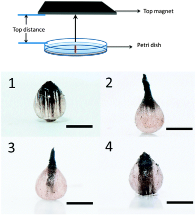
Fig. 3 shows particles synthesized when a single magnet is located above the Petri dish instead of below. When the distance between top magnet and Petri-dish is 5 cm, MNPs tend to migrate to the top side which has the strongest field strength and as a result, a teardrop shape particle is formed, Fig. 3(1). When the magnetic field is strong enough, rods can be formed that protrude out of the main droplet. After polymerization, the structure is locked in; see Fig. 3(2). The key characteristics of the ferromagnetic MNPs used in our experiment, that distinguishes them from their paramagnetic counterparts, is the quasi-irreversibility of the MNP chain formation process. When the external magnetic field is partially removed, the MNPs partially demagnetize very quickly, and gravity plays an important role in this case and draws the MNPs rod back into the droplet. However, MNPs still have magnetic attraction, which hold them together and dominate over Brownian motion, which would force the MNPs to redisperse. Therefore, as can be seen in Fig. 3(3 and 4), we can change the length of the rod that is formed on the particles.
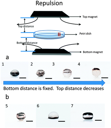
We also synthesized particles in the presence of two of the same permanent magnets, one above and below the Petri dish. These magnets can either be attracting or repelling one another. This is shown in Fig. 1. Depending on the configuration, we can generate different particle shapes and MNP patterns formed. In this case, we make the assumption that the magnet material's coercivity is sufficiently high that the magnetic field from the first magnet cannot substantially alter the magnetization of the second magnet.
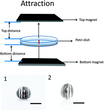
Fig. 4 shows that when the two magnets generate attractive forces, vertical MNP chains will again be generated. As is shown, they are parallel to the external field line. Although, in this case, the MNP chain formation can be controlled. For example, when the distance between the bottom magnet and Petri dish is fixed at 2 cm, decreasing the distance between the top magnet and Petri dish will increase the magnetic field flux density. As a result, the number of formed chains will decrease and the chains will become thicker.
When the two magnets are generating repulsive forces, the results shown in Fig. 5 are obtained; this is completely different than the attractive case. For example, at certain distances, opposing fields cancel each other out, leading to localized magnetic field minima. As a result, particles will experience forces that go outwards to the surrounding region of higher magnetic field.24,36 By controlling the local magnetic field strength, we can control the number and coverage of MNP chains on the particles. The coverage of horizontal chains can be controlled through adjustment of the relative distance between the top magnet and the Petri dish. In Fig. 5(a), we fix the distance between the bottom magnet and Petri dish at 2 cm, and the distance between the top magnet and the Petri dish is varied. When the top magnet is 5 cm from the Petri dish, the bottom magnetic field is stronger than the top one, and the chains mainly formed at the bottom of the particle (Fig. 5(1). When the distance between the top magnet and the Petri dish is decreased to 4 cm, the chains are observed throughout the particle, Fig. 5(2). When the distance between the top magnet and the Petri dish is decreased to 3.5 cm, the chains mainly occupy at the top half of the particle, Fig. 5(3). Finally, when the distance between the top magnet and the Petri dish is decreased to 3 cm, the MNP chains are mainly at the top side of the particle Fig. 5(4). When the repulsive magnetic field direction is horizontal (at certain magnet–magnet distances), the shape of the particle becomes ellipsoidal, as seen in Fig. 5(1–3). When the top magnet is close enough to the Petri dish (<3 cm), the drop will pull off the Teflon and float on the TMP/air interface to generate a particle with a flat surface (see ESI†). Additionally, by comparing Fig. 5(5) with Fig. 5(2), it can be seen that the number of MNP chains in the particles can be controlled by controlling the magnet–magnet distance. When the distance between the bottom magnet and Petri dish is 0.3 cm, and the top magnet is “far away” from the Petri dish (5 cm), we observed a hemispherical particle with off the MNP chains on the bottom Fig. 5(6). However, when both magnets are very close to the Petri dish (bottom is 0.3 cm and top is 2.4 cm), the particle became a semi-cuboid (Fig. 5(7)).
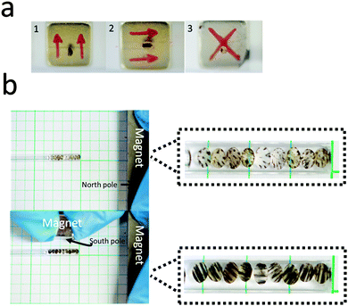
Next, we showed that the anisotropic particles generated from these experiments could be differentially manipulated depending on the MNP patterns in the particles and the magnetic field. As is shown in Fig. 6, the MNP chains in the particles are oriented parallel to the magnet's field line. In Video ESI,† we show that the same particle in Fig. 6 can be precisely controlled by an external magnet. Specifically, the anisotropic particle rotates and moves in a fashion that is synchronized with the external field, using a single rotation axis. It is also very easy to control the translational movement of the anisotropic particle under external magnetic field. Finally, we showed that our particles are very sensitive to external fields, and are capable of assembling into unique anisotropic patterns shown in Fig. 6. To accomplish this, synthesized anisotropic particles were added to a capillary tube with a diameter of ∼2 mm and filled with DI water. External magnets were placed near the tube, which resulted in particle orientation, which could be easily switched by changing the relative distances between the magnets and the tube.
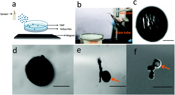
Finally, we showed that the synthesis of anisotropic particles could be scaled up, such that many particles could be synthesized in a simple manner and in a short time. In one example, we added the monomer solution to a spray bottle, and simply sprayed the monomer solution into the Petri dish assembly; the generated aerosol particles form the droplets that polymerize on the Teflon. This is illustrated in Fig. 7(a), and particles synthesized in this way can be seen in Fig. S6(a and b) (ESI†). An even more efficient approach to synthesize many particles simply and quickly, while allowing for the particle size to be easily tuned, is shown in Fig. 7(b). This approach simply uses a high pressure nitrogen gas stream directed at the tip of a tube, out of which a monomer solution could be pumped. The gas stream is capable of generating a fine mist, and the mist droplets (containing in this example monomer and photoinitiator) settle onto the Teflon surface. The drops on the Teflon could be polymerized by simple exposure to UV light. For this experiment, we used a pre-gel solution composed of poly(ethylene glycol) diacrylate (PEGDA (95% v/v)), photointiator 2,2-dimethoxy-2-phenylacetophenone (5% v/v) and MNPs (amount could be varied). The gas stream pressure and angle relative to the tip of the monomer solution delivery tube can be easily tuned to adjust the particle size. Microscope images (obtained with an Olympus optical microscope) of representative particles that were generated in this manner are shown in Fig. 7(c–f) as well as in ESI.† As can be seen from the representative microscope images, particles with diameters in the range of 5–400 μm could be readily generated. Furthermore, Fig. 7(c) shows that the structure of the magnetic particles could be retained after polymerization.
Conclusion
Using a simple setup composed of magnets interacting with MNPs, very complex particle structures, with very intricate MNP patterns locked inside each particle could be synthesized. The exact particle shape and arrangement of the MNP chains in the particles depended on if one or two magnets were used, and their distance away from the synthesis vessel. We showed that the synthetic conditions and setup are extremely robust, and can be used to synthesize many particles with predefined shape/configuration in a very reliable and reproducible manner. We also showed that the particles could be manipulated by external magnetic fields. Finally, the synthetic approach was shown to be scalable, such that many particles could be synthesized in parallel and the diameter can be reduced to hundreds of microns with system modification. These systems have many interesting potential applications for patterning, actuation, and for memory storage and encryption applications, which will be the topic of future studies.Acknowledgements
MJS acknowledges funding from the University of Alberta (the Department of Chemistry and the Faculty of Science), the Natural Sciences and Engineering Research Council of Canada (NSERC), the Canada Foundation for Innovation (CFI), and the Alberta Advanced Education & Technology Small Equipment Grants Program (AET/SEGP). WX acknowledges Alberta Innovates – Technology Futures for a Graduate Student Scholarship. We thank Prof. Mark Freeman for helpful discussions, Prof. Arthur Mar for assistance with the magnetic property measurements, and Prof. Ratmir Derda for helping with particle synthesis with a microfluidic device. We also thank Vincent Bizon for the constructing the magnet positioning/synthesis apparatus used in this study.References
- S. C. Glotzer, Science, 2004, 306, 419 CrossRef CAS PubMed.
- A. Walther and A. H. Müller, Chem. Rev., 2013, 113, 5194 CrossRef CAS PubMed.
- S. Mitragotri and J. Lahann, Nat. Mater., 2009, 8, 15 CrossRef CAS PubMed.
- T. Nisisako, T. Torii, T. Takahashi and Y. Takizawa, Adv. Mater., 2006, 18, 1152 CrossRef CAS PubMed.
- S. H. Kim, S. J. Jeon, W. C. Jeong, H. S. Park and S. M. Yang, Adv. Mater., 2008, 20, 4129 CAS.
- W. Gao and J. Wang, ACS Nano, 2014, 8, 3170 CrossRef CAS PubMed.
- H. Lee, J. Kim, H. Kim, J. Kim and S. Kwon, Nat. Mater., 2010, 9, 745 CrossRef CAS PubMed.
- D. Suzuki, S. Tsuji and H. Kawaguchi, J. Am. Chem. Soc., 2007, 129, 8088 CrossRef CAS PubMed.
- B. Liu, W. Wei, X. Qu and Z. Yang, Angew. Chem., Int. Ed., 2008, 120, 4037 CrossRef PubMed.
- L. Hong, S. Jiang and S. Granick, Langmuir, 2006, 22, 9495 CrossRef CAS PubMed.
- S. Jiang, M. J. Schultz, Q. Chen, J. S. Moore and S. Granick, Langmuir, 2008, 24, 10073 CrossRef CAS PubMed.
- Z. Nie, W. Li, M. Seo, S. Xu and E. Kumacheva, J. Am. Chem. Soc., 2006, 128, 9408 CrossRef CAS PubMed.
- S. N. Yin, C. F. Wang, Z. Y. Yu, J. Wang, S. S. Liu and S. Chen, Adv. Mater., 2011, 23, 2915 CrossRef CAS PubMed.
- P. Garstecki, M. J. Fuerstman, H. A. Stone and G. M. Whitesides, Lab Chip, 2006, 6, 437 RSC.
- P. Garstecki, I. Gitlin, W. DiLuzio, G. M. Whitesides, E. Kumacheva and H. A. Stone, Appl. Phys. Lett., 2004, 85, 2649 CrossRef CAS PubMed.
- D. Dendukuri, D. C. Pregibon, J. Collins, T. A. Hatton and P. S. Doyle, Nat. Mater., 2006, 5, 365 CrossRef CAS PubMed.
- R. Erhardt, A. Böker, H. Zettl, H. Kaya, W. Pyckhout-Hintzen, G. Krausch, V. Abetz and A. H. E. Müller, Macromolecules, 2001, 34, 1069 CrossRef CAS.
- R. Deng, S. Liu, F. Liang, K. Wang, J. Zhu and Z. Yang, Macromolecules, 2014, 47, 3701 CrossRef CAS.
- A. H. Gröschel, A. Walther, T. I. Löbling, J. Schmelz, A. Hanisch, H. Schmalz and A. H. E. Müller, J. Am. Chem. Soc., 2012, 134, 13850 CrossRef PubMed.
- S. Jiang and S. Granick, Langmuir, 2008, 24, 2438 CrossRef CAS PubMed.
- D. Zerrouki, J. Baudry, D. Pine, P. Chaikin and J. Bibette, Nature, 2008, 455, 380 CrossRef CAS PubMed.
- A. Walther, X. André, M. Drechsler, V. Abetz and A. H. E. Müller, J. Am. Chem. Soc., 2007, 129, 6187 CrossRef CAS PubMed.
- B. Liu, C. Zhang, J. Liu, X. Qu and Z. Yang, Chem. Commun., 2009, 3871 RSC.
- S. D. Kong, J. Lee, S. Ramachandran, B. P. Eliceiri, V. I. Shubayev, R. Lal and S. Jin, J. Controlled Release, 2012, 164, 49 CrossRef CAS PubMed.
- L. O. Mair, B. Evans, A. R. Hall, J. Carpenter, A. Shields, K. Ford, M. Millard and R. Superfine, J. Phys. D: Appl. Phys., 2011, 44, 125001 CrossRef.
- X. Feng, X. Guo and K. Qiu, Makromol. Chem., 1988, 189, 77 CrossRef CAS PubMed.
- L. Hu, Z. Chen and M. J. Serpe, Soft Matter, 2012, 8, 1009 Search PubMed.
- Y. D. Liu, J. Lee, S. B. Choi and H. J. Choi, Smart Mater. Struct., 2013, 22, 065022 CrossRef.
- B. J. Park, F. F. Fang and H. J. Choi, Soft Matter, 2010, 6, 5246 RSC.
- A. K. Vuppu, A. A. Garcia and M. A. Hayes, Langmuir, 2003, 19, 8646 CrossRef CAS.
- H. Singh, P. E. Laibinis and T. A. Hatton, Langmuir, 2005, 21, 11500 CrossRef CAS PubMed.
- N. T. Nguyen, G. Zhu, Y. C. Chua, V. N. Phan and S. H. Tan, Langmuir, 2010, 26, 12553 CrossRef CAS PubMed.
- J. J. Benkoski, S. E. Bowles, B. D. Korth, R. L. Jones, J. F. Douglas, A. Karim and J. Pyun, J. Am. Chem. Soc., 2007, 129, 6291 CrossRef CAS PubMed.
- R. Rungsawang, J. Da Silva, C. P. Wu, E. Sivaniah, A. Ionescu, C. H. Barnes and N. J. Darton, Phys. Rev. Lett., 2010, 104, 255703 CrossRef.
- J. Bacri and D. Salin, J. Phys., Lett., 1982, 43, 649 CrossRef CAS.
- F. Xu, C. M. Wu, V. Rengarajan, T. D. Finley, H. O. Keles, Y. Sung, B. Li, U. A. Gurkan and U. Demirci, Adv. Mater., 2011, 23, 4254 CrossRef CAS PubMed.
Footnote |
| † Electronic supplementary information (ESI) available. See DOI: 10.1039/c5sm01820j |
| This journal is © The Royal Society of Chemistry 2015 |

