
 Open Access Article
 This Open Access Article is licensed under a Creative Commons Attribution-Non Commercial 3.0 Unported Licence
Cucurbit[8]uril directed stimuli-responsive supramolecular polymer brushes for dynamic surface engineering†
Chi
Hu
a,
Feng
Tian
a,
Yu
Zheng
a,
Cindy Soo Yun
Tan
a,
Kevin R.
West
b and
Oren A.
Scherman
*a
aMelville Laboratory for Polymer Synthesis, Department of Chemistry, University of Cambridge, Cambridge, CB2 1EW, UK. E-mail: oas23@cam.ac.uk; Fax: +44 (0)1223 334866; Tel: +44 (0)1223 331508
bBP Oil UK Ltd, Whitchurch Hill, Pangbourne, Reading, Berkshire RG8 7QR, UK
First published on 6th July 2015
Abstract
In situ modification of surfaces with thin layers of polymers is of growing interest as adjustment of surface properties can be made on demand. We present herein a supramolecular ‘grafting to’ polymer brush via the recognition of surface-bound cucurbit[8]uril (CB[8]) rotaxanes towards end-functionalised polyethylene glycol (PEG). This dynamic supramolecular method represents advantages over traditional approaches, which employ covalent bond formation in the ‘grafting to’ process. Brush properties can be easily modified post-preparation by exchanging the polymers with small molecules in a controlled, reversible manner. Including both redox- and light-responsive guests in a single rotaxane entity, the CB[8]-mediated preparation of the polymer brush offers unique opportunities to switch the brush composition efficiently. While the PEG brushes are well hydrated in a good solvent (water) and stretch away from the surface, they collapse in a poor solvent (toluene), leading to the formation of a dense layer on the surface. This collapsed conformation protects the heteroternary complexes of CB[8]-rotaxane from dissociation and maintains the attachment of polymers on the surface.
1 Introduction
The application of surface engineering plays a vital role in the manufacture of almost every industrial product, from aeroplanes to iPhones and from wooden furnitures to coffee mugs. The modification of surfaces using polymer brushes has been extensively used to tailor surface properties such as wettability,1 biocompatibility,2,3 corrosion resistance4,5 and biolubrication6 of various materials, without altering their bulk properties.7 Polymer brushes provide an alternative and prove advantageous to other surface modification methods (e.g. self-assembled monolayers, SAMs) on account of their intrinsic large size, which gives rise to high mechanical and chemical robustness, coupled with a high degree of synthetic flexibility towards the introduction of a variety of functional groups.8,9 Furthermore, the advancement of stimuli-responsive polymer brushes that are capable of conformational and chemical changes on receiving external signals opens up the possibility to selectively tailor molecular assemblies and interfaces upon use of appropriate stimuli.9–11Ultrathin layers of polymer can be applied by depositing5 or spraying12,13 a polymeric coating from solution, for example. As this approach relies on the physisorption of the ‘sticky’ segments on polymers to surfaces, the adsorption is a reversible process and the resultant surface-bound polymers are not stable under severe conditions (e.g. high shear forces).14 Alternatively, densely grafted polymer layers (polymer brushes) permanently attached to surfaces via covalent chemical bonds can be accomplished by the so-called ‘grafting from’ or ‘grafting to’ strategies to form a more robust linkage at the interface. Surface-initiated polymerisation or the ‘grafting from’ method involves immobilising initiators onto surfaces to locally initiate polymerisation,8,15,16 while the ‘grafting to’ technique involves the formation of covalent bonds between reactive end-groups on polymers and complementary surface functionalities.7,17 The ‘grafting from’ method facilitates the fabrication of a wide range of polymer brushes with high grafting density, however, this approach requires a detailed characterisation of the brushes after preparation because of the discrepancy between the brushes and the corresponding polymers in bulk or solution phase. In contrast, the polymer can be thoroughly characterised by various chemical and physical methods prior to grafting in the ‘grafting to’ approach.18 While well-defined polymers with desired properties can be used for grafting to obtain uniform brushes, a major shortcoming of this ‘grafting to’ strategy is its low maximum brush thickness. This is because the tethered polymer layers act as an ‘excluded volume’ barrier.17 As its thickness increases, it is more difficult for the free polymer chains to diffuse through this barrier and reach the reactive sites on the surface.17
The ‘grafting to’ method is experimentally simple and several tethering methods have been reported in literature for preparation of polymer brushes on different substrates, e.g., silicon19–21 and gold.22–24 Generally, two steps are involved, i.e., the formation of ‘sticky’ segments on the surface and the reaction to ‘stick’ the end-functionalised polymer chains onto the surface. For example, silanols on silicon substrates25 are commonly reacted to form functional SAMs as the required ‘sticky’ groups. The grafting process employs reactions such as sulfonation,26 esterification,27 condensation28 or amidation29 in different pathways, between endgroups on the polymer and functionalised SAMs. One main limitation of the ‘grafting to’ method resides on the synthetic difficulty in attaching functional endgroups to polymers and preparing their matching ‘sticky’ segments on the surface. This ‘grafting to’ strategy is generally only applicable to a narrow range of polymer backbones as certain functionalities on polymers can reduce the efficiency of the grafting reactions. Thus, it is often necessary to re-adapt constantly the grafting strategies according to the chemical nature of the brush.
In order to develop a new universal procedure for preparing ‘grafting to’ brushes of a wider range of polymers, the possibility of exploiting the supramolecular chemistry of the symmetric macrocyclic host cucurbit[8]uril (CB[8]) to ‘stick’ end-functionalised polymers onto Au surfaces is discussed in this work for the first time. As it is solely the host–guest interaction that mediates the assembly of brushes, most commonly used polymer backbones are less likely to interfere with the grafting process. While polymeric assembly directed by host–guest interactions in solution has been extensively documented, supramolecular brush formation on solid substrates is rarely described.30 In 2010, Li and coworkers presented the grafting of functionalised poly(ε-caprolactone) on β-cyclodextrin modified cellulose.31 Reinhoudt and Huskens introduced the idea of a molecular printboard, where stable assemblies were prepared on β-cyclodextrin functionalised surfaces by employing multiple supramolecular interactions.32 None of these examples, however, explored the formation of densely packed polymer brushes. Recently, a CB[8]-based rotaxane structure was successfully prepared on Au surfaces by our group where CB[8] is threaded on a viologen (MV2+) core and prevented from dissociation away from the Au surface. Its binding behaviour towards second guests of CB[8], such as dopamine and azobenzene (Azo), to form heteroternary complexes was also demonstrated.33,34 The redox responsivity of the surface-bound CB[8]-rotaxane together with the photosensitivity incorporated by using Azo derivatives as the second guest are of significant interest in this work as they could offer multiple reversible controls over the formation of brushes, resulting in surfaces with active and tunable functionality. Also, the accessibility of mixed surface-functionalities allows tuning of polymer brush density at these surfaces with fine control, enabling a brush structure of controllable layer height and grafting density to be produced.
Herein, we report the design and construction of stimuli-responsive reversible polymer brushes in a supramolecular ‘grafting to’ fashion, utilising surface-bound CB[8]-rotaxanes as the ‘sticky’ segments on the surface (Fig. 1). The emphasis will be on the pivotal role of the dynamic heteroternary complex in reversibly controlling brush properties and broadening the scope of in situ surface engineering. The responsiveness of the resulting brushes to external stimuli in terms of structural change is also demonstrated, showing their importance for prospective applications in micro- and nanofluidics,35–37 controlled drug release,38,39 biocompatibility40,41 and controlled cell growth.42–44
 | ||
| Fig. 1 Schematic illustrations of CB[8]-mediated supramolecular ‘grafting to’ polymer brush preparation of (A) redox-driven assembly and disassembly of Np-PEG and (B) photoisomerisation-driven reversible assembly of Azo-PEG. | ||
2 Results and discussion
2.1 Preparation of Np-PEG brushes
In order to study the interaction between CB[8]-rotaxanes on Au surfaces and polymers end-functionalised with second guest naphthol (Np), Np-PEG was synthesised with its structure as shown in Fig. 1. Np-PEG was designed to have only one second guest moiety on each polymer chain, thus giving a better opportunity to ‘stand up’ and stretch away from the surface compared to multi-functionalised polymers (see Section 2.5). After immersing a non-patterned CB[8]-rotaxane functionalised Au substrate into an aqueous solution of Np-PEG (5 mM) for 30 min, an Np-PEG polymer brush with a height of 19 ± 1 nm was observed by ellipsometric measurement in the dry air. Contact angle (CA) measurements gave a value of 61° on a non-patterned surface of Np-PEG brushes, showing that a relatively more hydrophobic surface was formed compared to the CB[8]-rotaxane-terminated surface (CA = 43°). A patterned CB[8]-rotaxane functionalised Au substrate was prepared by micro-contact printing (μCP) and was used to visualise the attachment of Np-PEG polymers to the surface. As shown in Fig. 2A, SEM imaging confirmed the formation of Np-PEG polymer brushes through CB[8]-rotaxane directed surface recognition as the brushes were only found in the wide strips (180 μm in width) where CB[8]-rotaxanes were μCPed. AFM also showed the successful formation of a dotted polymer brush pattern, with a height of 20 ± 1 nm as given by the height profile of the cross section (Fig. 2C). | ||
| Fig. 2 (A) SEM image of linear polymeric arrays (180 μm (brush area) × 20 μm (gap width)). (B) AFM topography image of a patterned supramolecular brush surface in air. (C) Height profile obtained from the white line cross section as indicated by arrow in (B). The image was recorded in tapping mode. | ||
2.2 Solvent-induced morphological change
Responsiveness and adaptiveness of polymer brushes to external stimuli refer to changes of polymer chain conformation and is mostly reported on changes of macroconformations in solutions and melts when the mobility of chain segments is reasonably high.45,46 In order to probe the conformation of Np-PEG brushes in different solvent environments, characterisation in both good (water) and poor solvents (i.e., acetonitrile and toluene) for the brushes was carried out by tapping mode AFM imaging in a fluid cell. In a good solvent (Fig. 3A, C and E), the Np-PEG chains are well hydrated and extended to form a relatively smooth surface. AFM force–distance curves show the approach profiles obtained in water between a Si3N4 tip and the Np-PEG brushes on the surface. As shown by the solid line in Fig. 3E, the monotonically increasing repulsive forces observed during the approach are the typical signature of a polymer brush under compression in a good solvent.47 Change in the force–distance gradients under water occurred at a tip-surface distance of 27.3 nm, where the microfabricated AFM tip started to interact with the brush surface and deflect. This point in the force–distance curve denoted a change in chain stiffness during compression and is marked as the point at which the AFM tip reached the outer flexible hydrated polymer layer. As the tip moved closer to the surface, it subsequently encountered a more resistant compressed polymeric ‘core’, as indicated by the increased repulsion force. The greater height measured in water by AFM compared to the dry thickness given by ellipsometry is commonly observed and is most likely on account of the stretching of Np-PEG in water.48 | ||
| Fig. 3 Schematic illustration of the Np-PEG brush morphology on CB[8]-rotaxane-functionalised Au surface in (A) water (good solvent) and (B) toluene (poor solvent). AFM 3D topography images of Np-PEG brush in (C) water and (D) toluene. (E) Approach force–distance curves of Np-PEG polymer brushes with different grafting densities on CB[8]-rotaxane-functionalised Au surface. The solid line represents the profile of the brushes prepared by the addition of 100% Np-PEG (5 mM) to the functional surface. The dashed lines show the profile of the brushes prepared by adding a mixture of Np-PEG (5 mM) and small molecule Np (20 mM) to the surface. (F) Approach and retract profiles of a force–distance curve obtained in toluene between a Si3N4 AFM tip and the Np-PEG brushes on Au surface. | ||
To demonstrate control over the grafting density of polymer brushes, a mixture of the small molecule Np and Np-PEG ([Np] = 20 mM, [Np-PEG] = 5 mM) was used to form the brushes on the CB[8]-rotaxane terminated Au surface. As the small second guest molecule Np competes with Np-PEG to complex with CB[8]-rotaxanes on the surface, the grafting density of the resulting Np-PEG brush was reduced. The height of the newly formed brush was 5 ± 2 nm measured by ellipsometry in dry air, indicating that the presence of the small molecule Np hindered brush formation. The height of the newly formed brush in water was significantly reduced to 8.9 nm as indicated by the dashed lines in Fig. 3E. The decrease in height with increasing chain separation is a result of the reduced steric interactions between neighbouring chains. In the absence of small molecule Np, steric interactions between adjacent polymer chains in a confined environment force the chains to extend, thereby stretching away from the surface. With an increasing amount of Np, the increased chain separation provided enough space for the Np-PEG chains to adopt an entropically more favourable globular conformation, resulting in a decreased brush height.49 In order to show the necessity of having the Np group on the polymer chain, a CB[8] rotaxane-terminated Au surface was immersed in a mixture of PEG and Np-PEG ([PEG] = 20 mM, [Np-PEG] = 5 mM). The force–distance curve (Fig. S1C in the ESI†) does not show much difference compared to the curve for the brush prepared with 100% Np-PEG. Based on the results, the attachment of polymers onto the substrate is completely through controlled host–guest recognition of the CB[8]-rotaxanes on the surface, rather than by random physical adsorption.
In poor solvents, the liquid–monomer interaction is weaker than the monomer–monomer interaction, leading to significant changes in the structure of the brush. Solvent is expelled from the brush, creating a layer with a greater density and reduced height. As the solvent was changed from water to a mixture of acetonitrile and toluene (medium solvent, 1![[thin space (1/6-em)]](https://www.rsc.org/images/entities/char_2009.gif) :1 by volume, Fig. S3†), the morphology of the brush turned coarse and globules started to form instead of a continuous layer. When polymer brushes collapse in a poor solvent, the resulting layer will not in all cases be a flat continuous layer, as a continuous layer of polymer is unstable.50 This instability gives rise to a process referred to as constrained dewetting, which results in the polymer chains forming localised clumps on the surface, leaving some areas of the substrate exposed. The driving force behind this process is unfavourable intermolecular forces at the interface, as for the general dewetting of thin polymer films to minimise their contact with the poor solvent, with the added constraint of the covalent bonds to the surface.51 As the solvent was changed to toluene (poor solvent, Fig. 3B and D), the Np-PEG brush further dewetted and expelled solvent from the brush, leaving ‘pinned micelles’ on the surface. Note that these aggregates, although commonly referred to as “micelles”, are not true micelles. In contrast to micelles composed of surfactant molecules or block copolymers, the polymer chains composing the aggregate have no amphiphilic character. As significant changes in the height of the Np-PEG brushes were observed between the force curves in water and in toluene, the observed morphology change was due to contraction and collapse of the polymer brushes rather than reorientation of extended chains out of the z-plane by AFM imaging.
:1 by volume, Fig. S3†), the morphology of the brush turned coarse and globules started to form instead of a continuous layer. When polymer brushes collapse in a poor solvent, the resulting layer will not in all cases be a flat continuous layer, as a continuous layer of polymer is unstable.50 This instability gives rise to a process referred to as constrained dewetting, which results in the polymer chains forming localised clumps on the surface, leaving some areas of the substrate exposed. The driving force behind this process is unfavourable intermolecular forces at the interface, as for the general dewetting of thin polymer films to minimise their contact with the poor solvent, with the added constraint of the covalent bonds to the surface.51 As the solvent was changed to toluene (poor solvent, Fig. 3B and D), the Np-PEG brush further dewetted and expelled solvent from the brush, leaving ‘pinned micelles’ on the surface. Note that these aggregates, although commonly referred to as “micelles”, are not true micelles. In contrast to micelles composed of surfactant molecules or block copolymers, the polymer chains composing the aggregate have no amphiphilic character. As significant changes in the height of the Np-PEG brushes were observed between the force curves in water and in toluene, the observed morphology change was due to contraction and collapse of the polymer brushes rather than reorientation of extended chains out of the z-plane by AFM imaging.
As shown in the force vs. distance curves obtained as the AFM tip approached to and then withdrew from the Np-PEG brushes in toluene (Fig. 3F), the height of the Np-PEG brushes decreased from 27.3 nm in water to 19.9 nm in toluene, showing a steeper slope compared to the curves obtained in water as well as slight adhesion as denoted by the depression in the curve around 13 nm. This is indicative of a solvent induced collapse of the Np-PEG brushes, which generates a surface that is more adhesive to the AFM tip, most probably as a combination of the “micelle” formation and chain entanglement. Therefore, we attribute the change in measured thickness in the force curves of Np-PEG to the collapse of closely packed polymer chains in the brush due to dehydration in poor solvents. It is surprising to see that while the brush cannot be formed in toluene through the recognition of CB[8]-rotaxanes on the surface, the brush does not dissociate from the surface after being prepared in water and then washed with toluene for 2 days, as shown in Fig. S2 (ESI†). This is most likely because the brush collapsed to form a dense layer, protecting the CB[8]-rotaxanes and stopping the decomplexation of their heteroternary complexes.
2.3 Post-modification via small guest competition
In our method of preparing ‘grafting to’ polymer brushes via the host–guest complexation ability of CB[8]-rotaxanes that are pre-immobilised on Au surfaces, the grafting density of brushes can be readily manipulated as desired after preparation. For example, the brush density can be reduced by exchanging the polymer brush chains with small second guest molecules such as Np to form (Np·MV2+) ⊂ CB[8] instead of (Np-PEG·MV2+) ⊂ CB[8]. In the presence of a solution of Np (1 mM) flowing through the fluid cell in the AFM, the change in the height of the Np-PEG brushes was followed by force–distance spectroscopy, as shown in Fig. 4B(i). The height of the Np-PEG brushes was 27.3 nm before exposure to the Np solution. This value gradually decreased to 26.5 nm, 23.0 nm and 14.8 nm after 2 h, 4 h and 6 h of exposure, respectively. After 8 h the brushes were completely removed from the surface, leaving only (Np·MV2+) ⊂ CB[8]. The brush height as a function of exposure time obtained from force–distance spectroscopy showed that the height of the brushes decreased at a relatively slow rate in the first 5 h, as denoted by black squares in Fig. 5. This is because the small molecule Np initially needs to penetrate into the densely packed brush layer and break the steric interactions between adjacent PEG chains to be able to replace and remove Np-PEG from the surface. From 5 to 8 h, the brush height dropped rapidly, as at this point the brush layer is much less dense. The corresponding dry thickness of the brushes at 0 h, 2 h, 4 h and 6 h are 19 ± 1 nm, 13 ± 1 nm, 12 ± 1 nm and 8 ± 2 nm, respectively, as indicated by ellipsometry in air. After 8 h, the model used to measure the thickness of the polymer brushes by ellipsometry is no longer valid, as the brushes have been completely removed from the surface. CA measurements also displayed gradual changes from 61° (0 h), 59° (2 h), 50° (4 h), 48° (6 h) to 43° (8 h), with increased exposure time to the Np solution. In order to evaluate the effect of pure water on the disassembly of brushes, Np-PEG brushes were immersed in water for two days on a shaker and their thickness was measured by ellipsometry in air, giving a value of 14 ± 3 nm. This result suggests that because of the lack of guest competition, water by itself is not as efficient as Np solution in terms of reducing the density of Np-PEG brushes. | ||
| Fig. 4 (A) Schematic illustration of (i) Np-PEG brushes on CB[8]-rotaxane-functionalised surface with a flowing aqueous solution of small molecule Np (1 mM); (ii) Np-PEG brushes partially removed from the surface by competing Np and (iii) Np-PEG totally removed from the surface and replaced by Np. (B) Approach force–distance curves between a bare Si AFM tip and (i) Np-PEG brushes in an aqueous solution of Np (1 mM) at five different time intervals (0 h, 2 h, 4 h, 6 h and 8 h). The Np solution was pumped through the fluid cell by a syringe pump in the AFM at a rate of 100 μL min−1 throughout the measurement. (ii) (Np·MV2+) ⊂ CB[8] functionalised surface in an aqueous solution of Np-PEG (1 mM) at five different time intervals (0 h, 1 h, 2 h, 3 h and 4 h). The Np-PEG solution was pumped through the fluid cell by a syringe pump in the AFM at a rate of 100 μL min−1 throughout the measurement. | ||
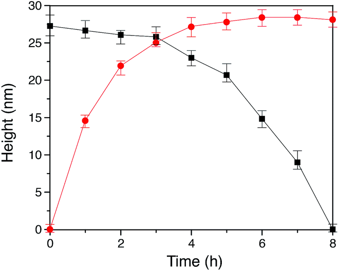 | ||
Fig. 5 Plot of polymer brush height vs. time showing (■) decreased height of the dynamic Np-PEG brushes as a function of Np small molecule contact time and ( ) increased polymer brush height as a function of Np-PEG assembly time on the (Np·MV2+) ⊂ CB[8] surface. ) increased polymer brush height as a function of Np-PEG assembly time on the (Np·MV2+) ⊂ CB[8] surface. | ||
As the guest exchange is a dynamic process, the (Np·MV2+) ⊂ CB[8] surface can be changed back to (Np-PEG·MV2+) ⊂ CB[8] by flushing the substrate with a solution of Np-PEG. As shown in Fig. 4B(ii), in 6 h the brushes were re-assembled on the surface with Np-PEG replacing small molecule Np and complexing with CB[8]-rotaxanes. The corresponding height data (see red dots in Fig. 5) showed a sharp increase in the first 3 h, which resulted from easy access to the CB[8]-rotaxane recognition units on the surface. Between 3 and 6 h, the rate of height increase slowed down, due to the gradual conformational rearrangement of polymer chains from a globular structure in solution to an extended brush stretching away from the surface. The process of changing Np to Np-PEG was quicker than removing Np-PEG with Np, suggesting the steric interactions between adjacent Np-PEG chains boosted the stability of the brush structure.
2.4 Mixed brushes for multiple responsiveness
In order to achieve diverse responsivities to external stimuli, PEG polymers containing an Azo functional end group as shown in Fig. 6A were synthesised. Azo-PEG brushes, prepared using a similar method to that described for the Np-PEG brushes, showed a height of 19 ± 1 nm as indicated by ellipsometry in dry air and a CA value of 61°. A height of 25.8 nm was measured by the force–distance profile in water while only 19.5 nm in toluene (Fig. S4A and D†). The height of the Azo-PEG brushes was reduced to 8.4 nm when the small molecule Azo derivative ([Azo] = 20 mM, [Azo-PEG] = 5 mM, 20%) was added (Fig. S4B†). The addition of unfunctionalised PEG during the preparation of brushes did not show any influence, confirming formation of the brush is through the recognition of the CB[8] rotaxanes on the surface (Fig. S4C†). | ||
| Fig. 6 (A) Optical microscopy images of the patterned Azo-PEG brush surface (i) after UV light irradiation in water (λ = 350 nm, 10 min); (ii) after visible light irradiation (λ = 420 nm, 30 min) or after reoxidation (O2, 30 min), showing an array of 10 μm (dot diameter) × 40 μm (interval length); (iii) after chemical reduction (Na2S2O4, 10 min). (B) Contact angle images of the corresponding states in (A). | ||
Compared to traditional approaches to prepare polymer brushes covalently bonded to the surface, one advantage of our supramolecular method presented in this work is its reversibility enabled by the dynamic binding nature of CB[8] rotaxanes. The reversible assembly of Azo-PEG brushes is explained below in detail as the complex shows both redox-controlled and photoisomerisation-driven responsivity, while the Np-PEG brushes only exhibit redox-controllable reversible formation (schematically illustrated in Fig. 1). In order to examine the assembly of Azo-PEG brushes under different redox conditions, a patterned brush substrate (Fig. 6B(ii)) was firstly soaked in an aqueous solution of Na2S2O4 (5 mM) for 10 min under a nitrogen atmosphere. The patterned Azo-PEG brushes were readily removed from the substrate as MV2+ was reduced to MV+˙, breaking the heteroternary complex of CB[8]-rotaxane (Fig. 6B(iii)). The pattern of brushes could be rewritten onto the substrate by immersing the substrate into the same Azo-PEG aqueous solution again for 30 min with a continuous flow of oxygen purging through the solution, oxidising MV+˙ back to MV2+ and reforming the ternary complex. The patterned Azo-PEG brush substrate was subsequently exposed to UV light (350 nm) for 10 min in water, resulting in the disappearance of the brushes (Fig. 6B(i)). The Azo functional group underwent trans-to-cis isomerisation induced by UV irradiation and dissociated from the CB[8]-rotaxane. The photoisomerisation of Azo is reversible and the cis-to-trans transition occurs upon exposure to visible light. The patterned Azo-PEG brushes were successfully reassembled onto the CB[8]-rotaxane substrate after irradiation under visible light (420 nm) for 30 min, as shown in Fig. 6B(ii). The corresponding changes in CA on an analogous non-patterned substrate are shown in Fig. 6C, with a value of 61° for the brush surface and 43° after removal of brushes. Surprisingly, the brushes prepared in water did not disassemble upon UV light irradiation in toluene, suggesting the dense layer formed by the collapsed brushes prevented the dissociation of CB[8] rotaxanes.
As Np and Azo functionalities exhibit different responses to external stimuli when complexed with CB[8], brushes consisting of mixed second guest moieties could be prepared to offer multiple control over brush properties. As shown in Fig. 7A(i), mixed brushes were designed containing 20% Np-PEG and 80% Azo-PEG (molecular ratio). Upon UV irradiation in water, Azo-PEG brushes were removed from the surface as the Azo moieties underwent trans-to-cis isomerisation, leaving only Np-PEG brushes on the surface as shown in Fig. 7A(ii). The Np-PEG brushes were removed in a second step where the MV2+ unit in the CB[8]-rotaxane was reduced using Na2S2O4, resulting in a reduced substrate as shown in Fig. 7A(iii), which could be reoxidised and reused. The corresponding approach force curves for the three states are shown in Fig. 7B. The mixed brushes showed an initial height of 26.0 nm, which was reduced to 5.9 nm after the removal of Azo-PEG brushes by applying UV light. After the removal of Azo-PEG brushes, chain separation was increased for the Np-PEG brushes and they adopted a more entropically favourable conformation instead of elongation, resulting in a decreased height. After reduction of the sample, no polymers were observed anymore as shown by the black curve in Fig. 7B, indicating the Np-PEG brushes were successfully removed. Comparing the two external stimuli, light is a selective stimulus that only affects brushes containing light-sensitive components such as the Azo moieties, whereas redox acts as a non-selective stimulus that directly addresses the CB[8] rotaxanes. The results suggest that by carefully designing the polymer composition to prepare the brushes, brush properties could be manipulated to a wide variety of desired values by applying external stimuli.
 | ||
| Fig. 7 (A) Schematic illustration of (i) mixed polymer brushes consisting of 20% Np-PEG and 80% Azo-PEG; (ii) after UV light irradiation (λ = 350 nm, 10 min), only Np-PEG remains on the surface; (iii) after chemical reduction (Na2S2O4, 10 min), all polymer brushes have been removed from the surface. (B) Approach force–distance curves taken in water between a Si3N4 AFM tip and the mixed Np-PEG/Azo-PEG brushes (20:80, orange), residual Np-PEG brushes (green) or the reduced CB[8]-rotaxane surface (black). | ||
2.5 Number of functionalities on polymers
As discussed previously, we assume that with only one second guest on the end of a polymer chain, the polymer–surface interaction is minimised to allow polymers to ‘stand up’ while offering enough attachment to the surface. According to this hypothesis, the brush height would be effectively decreased by increasing the number of second guests on a single polymer chain. In order to prove this, [3-(methacryloylamino)propyl]trimethylammonium chloride was copolymerised with Azo methacrylate and fluorescein (FITC) methacrylate (molecular ratio = 1000:25:10) to obtain poly(MPAC-Azo), as shown in Fig. 8A. Azo moieties function as second guests of CB[8] to facilitate the attachment of poly(MPAC-Azo) onto the CB[8]-functionalised Au surface and FITC realises direct imaging of patterned poly(MPAC-Azo) on the surface. μCP patterns as shown in Fig. 8B were prepared by soaking a patterned CB[8]-rotaxane functionalised substrate in an aqueous solution of poly(MPAC-Azo) ([Azo] = 5 mM) for 30 min. As fluorescence is only present on the dotted areas that were pre-functionalised with CB[8], it is indicative that the attachment of poly(MPAC-Azo) onto the substrate is through CB[8]-rotaxane mediated host–guest complexation.
 | ||
| Fig. 8 (A) Structure of an Azo-functionalised fluorescent random copolymer of [3-(methacryloylamino)propyl]trimethylammonium chloride. (B) Fluorescence microscopic image of the azobenzene-containing polymer brushes on a CB[8]-rotaxane functionalised Au substrate in a dotted array (10 μm in diameter, λex = 488 nm). Fluorescent array was prepared by the addition of poly(MPAC-Azo) (5 mM) to a micro-patterned CB[8]-functionalised substrate for 30 min in water. (C) Approach and retract profiles of a force–distance curve obtained in water between a film of poly(MPAC-Azo) on a CB[8]-functionalised Au substrate and a Si3N4 AFM tip. (D) Schematic illustration of multiple binding sites on poly(MPAC-Azo) chains to the CB[8]-rotaxane surface. | ||
Fig. 8C shows the force–distance curve in water between the poly(MPAC-Azo) film on surface and a bare Si tip. The gradient starts to change at a distance of 7.3 nm and this value is regarded as the swollen thickness of the poly(MPAC-Azo) film. After immersing an analogous non-patterned homogeneous CB[8]-functionalised Au substrate in the solution of poly(MPAC-Azo), a film of poly(MPAC-Azo) was formed on the surface with a height of 4 ± 0.6 nm, as indicated by ellipsometry measurements in air. As either the swollen thickness of 7.3 nm in water or the dry thickness of 4 nm in air is much smaller than the length of the polymer chain in poly(MPAC-Azo), the multifunctional polymers had adopted a ‘lying down’ conformation rather than ‘standing up’, as shown in Fig. 8D. The adoption of the ‘lying down’ morphology is probably due to the presence of multiple Azo functional groups as binding sites for the surface-bound CB[8] rotaxanes on a single polymer chain. The steric crowding of CB[8]-rotaxane binding sites on the surface by the already adsorbed ‘lying down’ polymers also makes it more difficult to achieve high grafting densities. The results suggest it is possible to alter brush properties by controlling the density of second guest functional groups on the polymer chains.
3 Conclusion
In conclusion, we have demonstrated a supramolecular approach to prepare ‘grafting to’ polymer brushes on gold surfaces by complexing end-functionalised polymers with surface-bound CB[8] rotaxanes. CB[8] was employed as the linking agent to ‘stick’ soft matter polymers to hard substrates by forming heteroternary complexes in water. The dynamic nature of the CB[8] mediated host–guest complexation facilitates in situ manipulation of brush properties including height and density by reversibly exchanging brush polymers with small guest molecules through dynamic competition. Potentially, more general changes in brush properties can be achieved by exploiting various polymers. Mixed brushes incorporating both Azo- and Np-PEG polymers exhibit a two-step responsivity to external stimuli, firstly disassembling Azo-PEG polymers under UV light and then removing Np-PEG brushes upon reduction. Surprisingly, the CB[8]-mediated polymer brushes do not disassemble in toluene and acetonitrile, even though complexes of CB[8] are known to dissociate in organic solvents. This is probably because the PEG brushes collapse in organic solvents to form a dense layer, covering and protecting the surface-bound CB[8] rotaxanes. This supramolecular method provides a platform to prepare polymer brushes and broaden the scope of attaching soft matter onto solid substrates. Future work will focus on the applications of these smart materials in fluid flow and bioadhesion.Acknowledgements
We thank Dr Ziyi Yu for help with the μCP masks. C. Hu is grateful to BP for supporting this work and Hughes Hall College Cambridge for a student scholarship. Dr F. Tian thanks CSC Cambridge Scholarship and Duke of Edinburgh Scholarship. Dr Y. Zheng is grateful for an ERC starting investigator grant (ASPiRe 240629) for financial support. C. S. Y. Tan thanks Department of Higher Education, Ministry of Education of Malaysia and Universiti Teknologi MARA (UiTM) of Malaysia for student scholarship.References
- O. Azzaroni, A. Brown and W. Huck, Adv. Mater., 2007, 19, 151–154 CrossRef CAS
.
- A. Mizutani, A. Kikuchi, M. Yamato, H. Kanazawa and T. Okano, Biomaterials, 2008, 29, 2073–2081 CrossRef CAS PubMed
- R. Iwata, P. Suk-In, V. P. Hoven, A. Takahara, K. Akiyoshi and Y. Iwasaki, Biomacromolecules, 2004, 5, 2308–2314 CrossRef CAS PubMed
- S. Yuan, S. Pehkonen, B. Liang, Y. Ting, K. Neoh and E. Kang, Corros. Sci., 2011, 53, 2738–2747 CrossRef CAS
- C. Tan and D. Blackwood, Corros. Sci., 2003, 45, 545–557 CrossRef CAS
- U. Raviv, S. Giasson, N. Kampf, J.-F. Gohy, R. Jerome and J. Klein, Nature, 2003, 425, 163–165 CrossRef CAS PubMed
- S. T. Milner, Science, 1991, 251, 905–914 CrossRef CAS PubMed
- S. Edmondson, V. L. Osborne and W. T. S. Huck, Chem. Soc. Rev., 2004, 33, 14–22 RSC
- F. Zhou and W. T. S. Huck, Phys. Chem. Chem. Phys., 2006, 8, 3815–3823 RSC
- M. A. C. Stuart, W. T. S. Huck, J. Genzer, M. Muller, C. Ober, M. Stamm, G. B. Sukhorukov, I. Szleifer, V. V. Tsukruk, M. Urban, F. Winnik, S. Zauscher, I. Luzinov and S. Minko, Nat. Mater., 2010, 9, 101–113 CrossRef PubMed
- F. Liu and M. W. Urban, Prog. Polym. Sci., 2010, 35, 3–23 CrossRef CAS
- D. Y. Ryu, K. Shin, E. Drockenmuller, C. J. Hawker and T. P. Russell, Science, 2005, 308, 236–239 CrossRef CAS PubMed
- P. Mansky, Y. Liu, E. Huang, T. P. Russell and C. Hawker, Science, 1997, 275, 1458–1460 CrossRef CAS
- B. Zhao and W. Brittain, Prog. Polym. Sci., 2000, 25, 677–710 CrossRef CAS
- R. Barbey, L. Lavanant, D. Paripovic, N. Schüwer, C. Sugnaux, S. Tugulu and H.-A. Klok, Chem. Rev., 2009, 109, 5437–5527 CrossRef CAS PubMed
- M. Husseman, E. E. Malmström, M. McNamara, M. Mate, D. Mecerreyes, D. G. Benoit, J. L. Hedrick, P. Mansky, E. Huang, T. P. Russell and C. J. Hawker, Macromolecules, 1999, 32, 1424–1431 CrossRef CAS
- B. Zdyrko and I. Luzinov, Macromol. Rapid Commun., 2011, 32, 859–869 CrossRef CAS PubMed
- R.-V. Ostaci, D. Damiron, S. Capponi, G. Vignaud, L. Léger, Y. Grohens and E. Drockenmuller, Langmuir, 2008, 24, 2732–2739 CrossRef CAS PubMed
- W. Zhao, G. Krausch, M. H. Rafailovich and J. Sokolov, Macromolecules, 1994, 27, 2933–2935 CrossRef CAS
- I. Luzinov, D. Julthongpiput, A. Liebmann-Vinson, T. Cregger, M. D. Foster and V. V. Tsukruk, Langmuir, 2000, 16, 504–516 CrossRef CAS
- I. Luzinov, D. Julthongpiput, H. Malz, J. Pionteck and V. V. Tsukruk, Macromolecules, 2000, 33, 1043–1048 CrossRef CAS
- W. Taylor and R. A. L. Jones, Langmuir, 2010, 26, 13954–13958 CrossRef CAS PubMed
- M. K. Corbierre, N. S. Cameron and R. B. Lennox, Langmuir, 2004, 20, 2867–2873 CrossRef CAS PubMed
- H. Yockell-Lelièvre, J. Desbiens and A. M. Ritcey, Langmuir, 2007, 23, 2843–2850 CrossRef PubMed
- D. Julthongpiput, Y.-H. Lin, J. Teng, E. R. Zubarev and V. V. Tsukruk, J. Am. Chem. Soc., 2003, 125, 15912–15921 CrossRef CAS PubMed
- Y. Tran and P. Auroy, J. Am. Chem. Soc., 2001, 123, 3644–3654 CrossRef CAS PubMed
- D. Julthongpiput, Y.-H. Lin, J. Teng, E. R. Zubarev and V. V. Tsukruk, J. Am. Chem. Soc., 2003, 125, 15912–15921 CrossRef CAS PubMed
- P. Auroy, L. Auvray and L. Léger, Phys. Rev. Lett., 1991, 66, 719–722 CrossRef CAS PubMed
- K. B. Walters and D. E. Hirt, Macromolecules, 2007, 40, 4829–4838 CrossRef CAS
- Q. An, J. Brinkmann, J. Huskens, S. Krabbenborg, J. de Boer and P. Jonkheijm, Angew. Chem., Int. Ed., 2012, 51, 12233–12237 CrossRef CAS PubMed
- Q. Zhao, S. Wang, X. Cheng, R. C. M. Yam, D. Kong and R. K. Y. Li, Biomacromolecules, 2010, 11, 1364–1369 CrossRef CAS PubMed
- J. Huskens, M. A. Deij and D. N. Reinhoudt, Angew. Chem., Int. Ed., 2002, 41, 4467–4471 CrossRef CAS
- C. Hu, Y. Lan, F. Tian, K. R. West and O. A. Scherman, Langmuir, 2014, 30, 10926–10932 CrossRef CAS PubMed
- C. Hu, Y. Zheng, Z. Yu, C. Abell and O. A. Scherman, Chem. Commun., 2015, 51, 4858–4860 RSC
- H. G. Craighead, Science, 2000, 290, 1532–1535 CrossRef CAS PubMed
- I. Luzinov, S. Minko and V. V. Tsukruk, Soft Matter, 2008, 4, 714–725 RSC
- N. I. Abu-Lail, M. Kaholek, B. LaMattina, R. L. Clark and S. Zauscher, Sens. Actuators, B, 2006, 114, 371–378 CrossRef CAS
- N. Nath and A. Chilkoti, Adv. Mater., 2002, 14, 1243–1247 CrossRef CAS
- A. Bajpai, S. K. Shukla, S. Bhanu and S. Kankane, Prog. Polym. Sci., 2008, 33, 1088–1118 CrossRef CAS
- T. K. Tam, M. Ornatska, M. Pita, S. Minko and E. Katz, J. Phys. Chem. C, 2008, 112, 8438–8445 CAS
- F. J. Xu, S. P. Zhong, L. Y. L. Yung, E. T. Kang and K. G. Neoh, Biomacromolecules, 2004, 5, 2392–2403 CrossRef CAS PubMed
- T. P. Russell, Science, 2002, 297, 964–967 CrossRef CAS PubMed
- K. Nishida, M. Yamato, Y. Hayashida, K. Watanabe, N. Maeda, H. Watanabe, K. Yamamoto, S. Nagai, A. Kikuchi and Y. Tano, Transplantation, 2004, 77, 379–385 CrossRef PubMed
- M. A. Cole, N. H. Voelcker, H. Thissen and H. J. Griesser, Biomaterials, 2009, 30, 1827–1850 CrossRef CAS PubMed
- S. Minko, J. Macromol. Sci., Polym. Rev., 2006, 46, 397–420 CrossRef CAS
- N. Backmann, N. Kappeler, T. Braun, F. Huber, H.-P. Lang, C. Gerber and R. Y. H. Lim, Beilstein J. Nanotechnol., 2010, 1, 3–13 CrossRef CAS PubMed
- H. J. Taunton, C. Toprakcioglu, L. J. Fetters and J. Klein, Nature, 1988, 332, 712–714 CrossRef CAS
- D. Jones, J. Smith, W. Huck and C. Alexander, Adv. Mater., 2002, 14, 1130–1134 CrossRef CAS
- D. I. Dimitrov, A. Milchev and K. Binder, J. Chem. Phys., 2007, 127, 084905 CrossRef CAS PubMed
- T. Lee, S. C. Hendy and C. Neto, Macromolecules, 2012, 45, 6241–6252 CrossRef CAS
- J. Huh, C.-H. Ahn, W. H. Jo, J. N. Bright and D. R. M. Williams, Macromolecules, 2005, 38, 2974–2980 CrossRef CAS
Footnote |
| † Electronic supplementary information (ESI) available. See DOI: 10.1039/c5sc01496d |
| This journal is © The Royal Society of Chemistry 2015 |