A solar assisted microbial electrolysis cell for hydrogen production driven by a microbial fuel cell
Li-Li
Wan
,
Xiao-Jing
Li
,
Guo-Long
Zang
*,
Xin
Wang
,
Yue-Yong
Zhang
and
Qi-Xing
Zhou
*
MOE Key Laboratory of Pollution Processes and Environmental Criteria/Tianjin Key Laboratory of Environmental Remediation and Pollution Control/College of Environmental Science and Engineering, Nankai University, Tianjin 300071, China. E-mail: guolongz@mail.ustc.edu.cn; zhouqx@nankai.edu.cn
First published on 23rd September 2015
Abstract
Here, we report a new microbial electrolysis cell (MEC) system for hydrogen generation that was composed of a microbial fuel cell (MFC) and a bio-photoelectrochemical cell (BPEC). The BPEC consisted of a photocathode and a microbially-catalyzed anode. In the new MEC system, hydrogen was produced by the BPEC photocathode when it was illuminated with visible light, with the voltage for electrolysis supplied by the MFC. The electrons produced from the MFC anode were transferred to the BPEC photocathode through an external circuit and then photogenerated holes captured some of the electrons emitted by the MFC anode under visible light. This prevented the recombination of the photogenerated hole and electron pairs, leaving more photogenerated electrons available for hydrogen evolution reactions. This also allowed the remaining electrons from the MFC anode to participate in hydrogen evolution reactions. Under visible light, hydrogen was continuously produced from the new MEC system, with a maximum current density of 0.68 A m−2 and an average hydrogen-production rate of 1.35 ± 0.15 mL h−1.
1. Introduction
Bioelectrochemical systems are emerging as renewable energy technologies that can be used for sustainable wastewater treatment and production of value-added chemicals.1,2 These systems are known as microbial fuel cells (MFC) and microbial electrolysis cells (MEC), respectively. The MEC, a special MFC, can be used for hydrogen generation by applying an external voltage or augmenting the cathode potential.3,4 Compared with alternative hydrogen production technologies such as dark fermentation and photosynthesis, the MEC has shown some advantages, such as requiring lower energy input and having higher hydrogen yield.5 However, there are still some shortages limiting its application: (i) relatively high overpotential is needed because of the kinetically slow cathodic reaction;6 (ii) theoretically, through the microbial electrolysis of acetate, a voltage of 0.6 V or more was used for a high efficiency hydrogen production.7To facilitate the sluggish cathode reaction, electrocatalysts have been applied. Because of high capacity for hydrogen evolution reaction under optimized conditions of mass transport, noble metals such as platinum (Pt) are the most efficient catalyst for hydrogen evolution reaction.8 But the high cost and negative environmental impacts when mines and extracts Pt make this option unattractive, because it is not environmentally sustainable or economically feasible for large scale production.9 Other catalysts, such as nickel foam, stainless steel and molybdenum disulfide, are promising alternatives to noble metal catalysts and have recently attracted attentions.10–12 However, the use of any metal catalyst is costly because they have to be constantly replaced, due to deactivation problems.13,14 Using microorganisms as biocatalyst in the MEC biocathode for hydrogen production has recently been demonstrated to be a viable alternative to metal catalysts.15–18 But the rate of hydrogen production for MEC with biocatalysts was not as high as the MEC with metal catalysts. To promote the performance of biocathode, researchers constructed a graphene modified biocathode, but more energy input was needed in this test and the graphene was costly.19 Therefore, finding a way to improve cathode efficiency and reduce expenditure on cathode is urgent.
Except for kinetically slow cathodic reaction, the needing of extra energy input is another problem that hampers MEC for commercial application. Recently, the extra energy needed for cathodic hydrogen evolution has been supplied by various sources and we briefly describe some of the experimental designs. An acetate-powered microbial electrolysis cell-microbial fuel cell (MEC-MFC) coupled system for hydrogen production was one of the first systems investigated. In this system, hydrogen was produced in an MEC and the extra power was supplied by an MFC. With a hydrogen production rate of 2.2 ± 0.2 mL L−1 d−1, the MEC-MFC coupled system demonstrated an effective means of in situ utilization of the power generated from MFCs.7 In an effort to use renewable solar energy, a dye-sensitized solar cell (DSSC) was used to convert sunlight to electric energy and power the MEC for hydrogen production.20 Different from the last research, a solar-driven microbial photoelectrochemical cell consisted of a p-type Cu2O nanotube array photocathode and a bio-anode was constructed.21 It was the first time that solar energy was implanted into MEC. This device proved synergistic effects between microbial cells and semiconductor nanowire systems, but no hydrogen was detected. Lately, a novel bio-photoelectrochemical cell that consisted of a MoS3 modified p-type Si nanowires photocathode and a bioanode was reported. To overcome the cathode overpotential, this device augmented the cathode potential by maintaining acidic catholyte pH.22
Here we report a new MEC system for hydrogen production, which is a bio-photoelectrochemical cell (BPEC) powered by an MFC. The BPEC consists of p-type Si nanowires (SiNWs), a photocathode and a microbially-catalyzed anode. In the BPEC, to build a no inner bias condition, same electrolyte (pH 7) is used in both cathode chamber and anode chamber. The MFC is used as extra voltage supply to overcome cathode overpotential.
2. Experimental
2.1. Configuration and operation of the MFC
A single-chamber cubic-shaped MFC (4 cm long and 3 cm in diameter) contained an acetone-cleaned carbon fiber brush (25 mm in diameter) anode23 and a rolling activated carbon air-cathode (7 cm2 surface area). The air-cathode was made as described previously.24 The MFCs were inoculated using a pre-acclimated bacterial suspension from an MFC operated for over 1 year.25 The reactors were filled with 28 mL anaerobic medium composed of phosphate buffer nutrient solution (PBS) containing Na2HPO4·12H2O, 10.317 g L−1; NaH2PHO4·2H2O, 3.321 g L−1; NH4Cl, 0.31 g L−1; KCl, 0.13 g L−1, trace minerals (12.5 mL L−1), vitamins (5 mL L−1) and substrate sodium acetate (1.0 g L−1).26 All reactors were operated in a 30 °C temperature controlled room and refilled when the voltage decreased to less than 50 mV. Throughout the acclimation period, the MFCs were connected to an external resistance of 1 kΩ.2.2. Electrode preparation for BPEC
The substrate was built with p-type Silicon (100) wafers (20 × 40 mm, 600 μm thick, 5–20 Ω cm resistivity). SiNWs were fabricated using a chemical etching method.27,28 Si wafers were degreased with ultra-sonication in acetone for 15 min and ethanol for 15 min, and then the degreased Si wafers were ultrasonically immersed in a mixture solution of H2O2 (30%) and H2SO4 (98%) (1![[thin space (1/6-em)]](https://www.rsc.org/images/entities/char_2009.gif) :
:![[thin space (1/6-em)]](https://www.rsc.org/images/entities/char_2009.gif) 3, v
3, v![[thin space (1/6-em)]](https://www.rsc.org/images/entities/char_2009.gif) :
:![[thin space (1/6-em)]](https://www.rsc.org/images/entities/char_2009.gif) v) for 15 min. Hydrofluoric acid (5%) was used to dissolve the oxide layer formed during the previous procedure. The cleaned Si substrates were dipped in a mixture of 20 mM AgNO3 and 4 M HF acid for 1 h at 50 °C. After a rinse with deionized water, the etched wafers were immersed in diluted HNO3 for 30 min to remove residual Ag. The SiNWs were cleaned with 5% HF to remove the oxide layer, and rinsed with deionized water. A field-emission scanning electron microscope was used to characterize the morphology of the cathode samples.
v) for 15 min. Hydrofluoric acid (5%) was used to dissolve the oxide layer formed during the previous procedure. The cleaned Si substrates were dipped in a mixture of 20 mM AgNO3 and 4 M HF acid for 1 h at 50 °C. After a rinse with deionized water, the etched wafers were immersed in diluted HNO3 for 30 min to remove residual Ag. The SiNWs were cleaned with 5% HF to remove the oxide layer, and rinsed with deionized water. A field-emission scanning electron microscope was used to characterize the morphology of the cathode samples.
2.3. Photoelectrochemical measurement of the photocathode
The performance of the photocathode was estimated in a three-electrode configuration with SiNWs photocathode as working electrode, a platinum foil as counter electrode and an Ag/AgCl as reference electrode. A 500 W xenon lamp (CHF-XM-500 W, Beijing Trusttech Co., China) with a visible-light filter (>400 nm)29 was used as visible-light source (light intensity was about 1200 mW cm−2) to illuminate the photocathode. Liner sweep voltammetry were measured from −1.2 to 0.6 V at a scan rate of 10 mV s−1 with a potentiostat (660C, Chenhua Instruments Co., China), and PBS (pH 7) was used as electrolyte. As dark treatment, the three-electrode cell was encased with aluminum foil. To describe the transient current responses to on–off cycles of illumination, under chopped illumination, manual shielding/unshielding light was adopted.2.4. Construction and operation of the new MEC system
The new MEC system was composed of a single-chamber, cubic-shaped MFC and a BPEC. The anode chamber and the cathode chamber of the BPEC were made of glass, and the two chambers were separated by a 4.5 cm2 cation exchange membrane (Ultrex CMI7000, Membranes International Inc., US). There was a quartz glass window (3 × 5 cm) in the front of the BPEC's anode chamber. A microbially-catalyzed anode collected from MFC and a SiNWs photoelectrode were used as the anode and photocathode in the BPEC, respectively. The SiNWs photocathode was hung parallelly with the quartz glass window. The anode chamber of the BPEC was filled with liquid same as the MFC medium (325 mL, pH 7.0) and autoclaved PBS was utilized as the catholyte (200 mL, pH 7.0). The remaining space in the cathode chamber (125 mL) was used for hydrogen collection. Oxygen and hydrogen in the electrolyte was removed with N2 and stirred catholyte with a magnetic stirrer. The MFC, BPEC and a 10 Ω resistor were connected in a circuit, creating a new MEC system.To monitor the photocurrent of the new MEC system, voltage under 10 Ω resistance was collected by a potentiostat under intermittent illumination by manually covering and uncovering the light. As a control, the MFC in the new MEC system was removed, and the photocurrent generated by BPEC was tested.
To prove the hydrogen production performance, the new MEC system was constructed as mentioned above and a 500 W xenon lamp was used as a visible-light source. As a dark treatment, the xenon lamp was turned off, and the cathode and anode chambers were encased in aluminum foil. As a test for the impact of the extra voltage on hydrogen production, the MFC in the new MEC system was removed, leaving the BPEC and resistor intact. All tests were conducted at ambient temperature (25 °C). In this study, the new MEC system was run two cycles to demonstrated its stability. Same SiNWs photocathode was used (the SiNWs photocathode obtained from cycle 1 was washed with deionized water for several times and dipped in 5% HF for 20 seconds, then washed with deionized water again) and electrolyte of the BPEC and MFC was changed into fresh medium in cycle 2.
The hydrogen volume was measured using a gas chromatograph (model SP-6800A, Lunan Co., China) equipped with a thermal conductivity detector and a 1.5 m stainless-steel column with argon as the carrier gas (30 mL min−1). The total amount of hydrogen produced was calculated by multiplying the hydrogen content in a 200 μL gas sample (normalized to per mL) with the headspace volume of the BPEC cathode chamber (125 mL).
3. Results
3.1. MFC performance
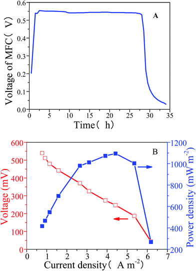
The voltage of the MFC in the new MEC system reached 0.5 V one hour after the chamber was refilled with PBS and plateaued for 26 hours (Fig. 1A). The polarization and power characterization curve of the MFC demonstrated the relationship among voltage, current density and power density (Fig. 1B). When the current density was 4.4 A m−2, the maximum power density was 1094.7 mW m−2. The voltage decreased linearly with increasing current density, suggesting that the ohmic losses were mainly caused by resistance between the electrodes and the electrolyte. Hence, the MFC's output voltage was stable enough and output power density was high enough to be used as an extra power supply.3.2. Photocathode performance
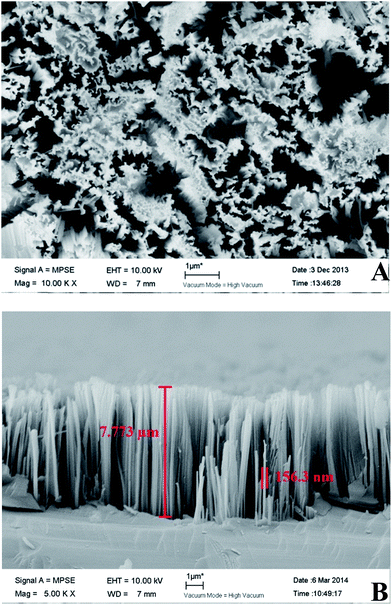
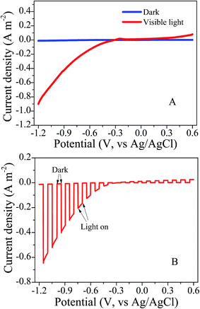
Images from a field-emission scanning electron microscope were collected from Si substrates with silicon nanowires (Fig. 2). Silicon nanowire arrays were successfully synthesized at a length of approximately 7.7 μm and a diameter of approximately 156 nm.We recorded the linear sweep voltammetry at a scanning rate of 10 mV s−1 from the SiNWs photocathode in dark and visible light treatments (Fig. 3A). There was a pronounced photoresponse under visible light in comparison with the dark treatment, and almost no current could be produced in the dark. The onset potential of the photoelectrode reached approximately −0.3 V vs. Ag/AgCl under visible light illumination. This demonstrated that the photoelectric chemical catalytic performance of the photoelectrode was high. When extra voltage across the photoelectrode exceeded −0.3 V, the cathode reaction would happen. With same scanning rate and range, the transient current responses to on–off cycles of illumination on the photocathode were carried out (Fig. 3B). Notably, the photoelectrochemical activity of SiNWs photocathode was considerable.
3.3. Photocurrent of the new MEC system
With voltage collecting from 10 Ω resistor, the circuital current was calculated according to Ohm's law and was normalized by photocathode surface area (8 cm−2). The current density generated by the new MEC system under visible light was 0.65–0.68 A m−2, while the current density was only 0.49–0.52 A m−2 in the absence of light (Fig. 4). Thus the maximum photocurrent density of the new MEC system was about 0.16 A m−2. Furthermore, without the MFC in the series circuit, the current density of the BPEC under visible light was 0.19–0.21 A m−2. Compared with the BPEC, the new MEC system produced a stronger and more stable current density. Based on our results we proposed that, in the new MEC system, electrons released by the MFC anode migrated through the external electrical circuit to the photocathode where they combined with photoexcited holes, avoided recombination of the photogenerated carriers, made it possible for stronger and more stable photocurrent.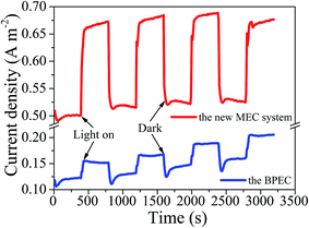 | ||
| Fig. 4 Current density over time with and without visible light irradiation. Red line = the new MEC system. Blue line = the BPEC alone. | ||
3.4. Hydrogen production performance of the new MEC system
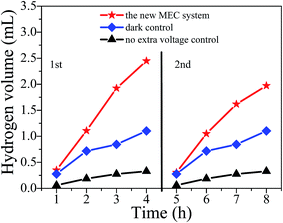
Hydrogen gas was continuously produced in the cathode chamber of the BPEC and no oxygen was detected in any gas samples. Fig. 5 showed the plot of hydrogen production over time. The hydrogen production rate of the new MEC system was 1.46 mL h−1 in the first cycle and was 1.24 mL h−1 in the second cycle (1.35 ± 0.15 mL h−1 in average of the two cycles). In the new MEC system, hydrogen production was almost linear over time. In the dark treatment the hydrogen production rate reached 0.72 mL h−1. Actually, hydrogen was not expected to be detected when this treatment was set. It is possible reason was listed in discussion. In the treatment without MFC as extra voltage, but with visible light, the hydrogen production in the cathode chamber of the BPEC was about 0.21 mL h−1. It seemed that in this treatment, hydrogen was produced by photocorrosion of the SiNWs photocathode.30–324. Discussion
In this study we designed and tested a new MEC system for hydrogen production under visible light. Our innovative design was a hybrid device of a BPEC and a MFC, the BPEC was the hydrogen production cell while the MFC was the energy supply. Compared with a previous study which overcame the overpotential of hydrogen evolution reaction by inner bias,23 the new MEC system adopted neutral solution (PBS, pH 7) as the electrolyte for both BPEC anode chamber and cathode chamber, reached a condition that had no inner bias. The extra electricity for electrolysis was supplied by an MFC.In the system, a series of bioelectrochemical and photoelectrochemical reactions were involved (Fig. 6A). The BPEC and the MFC were connected as shown in the theoretical diagram of the new MEC system (Fig. 6B). In the MFC, acetate were oxidized to protons and electrons by microbial catalysts on the anode. The electrons were continuously transported to the photocathode through an external electrical circuit. Under visible light, photoexcited holes and electrons generated at the photocathode and the photoexcited holes captured the electrons generated on the MFC anode, leading to a reduction in the recombination of photogenerated carriers. Acetate on the BPEC anode were also oxidized to protons and electrons under the catalysis of microbes. The protons were transported to the BPEC catholyte through a cation exchange membrane, while electrons were transported to the MFC air-cathode through an external electrical circuit. Protons from the BPEC anode were reduced by electrons transferred from MFC anode, forming hydrogen gas on the photocathode. On the MFC air-cathode, oxygen as terminal electron acceptor was reduced to H2O by accepting the electrons coming from the BPEC anode. The reactions were sustained in the new MEC system under visible light, greatly improving the photocatalytic efficiency and hydrogen production volume.
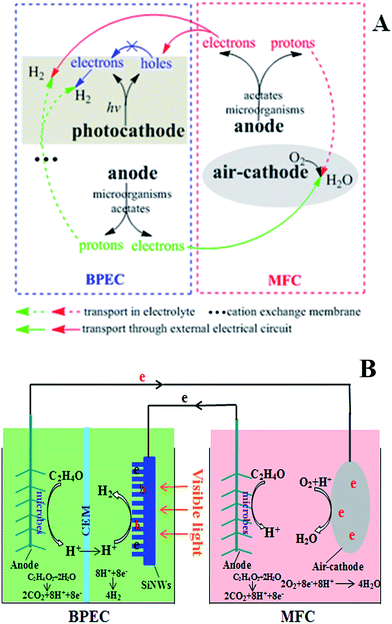 | ||
| Fig. 6 (A) Details of the bioelectrochemical and photoelectrochemical reaction schemes. (B) Schematic of the new MEC system. | ||
In the dark treatment, photoexcited electrons and holes were not present and subsequent reactions did not occur. In theory, hydrogen could not be generated in the dark, but we detected a relatively small amount of hydrogen. We proposed that the SiNWs electrode in this test was similar to an MEC conductor electrode because of its low resistivity (5–20 Ω cm), and the new MEC system operating in the dark was similar to a conventional MEC with the extra power from the MFC. The hydrogen was produced on the photocathode by combining electrons generated on the MFC anode with protons generated by the BPEC anode. This suggests that under visible light, hydrogen was produced in two ways in the new MEC system: protons from the BPEC anode combined with photoexcited electrons and electrons generated on the MFC anode, respectively.
In recent years, several hybrid devices for hydrogen production were constructed, such as MEC-MFC-coupled system,7 photoelectrochemical cell-microbial fuel cell hybrid device33 and self-sustained BPEC.22 In MEC-MFC-coupled system, the average hydrogen-producing rate was about 1.98 mL d−1 during the initial 7 days; in photoelectrochemical cell-microbial fuel cell hybrid device, within the increased rapidly initial 5 h, the total gas volume was less than 1.5 mL and the gas was a mixture of hydrogen and oxygen; while in self-sustained BPEC, the average hydrogen-producing rate was about 1.00 mL h−1. Compared with devices mentioned above, the new MEC system has a great hydrogen production performance (1.35 ± 0.15 mL h−1). To explain this, we proposed that, SiNWs semiconductors had two functions in the BPEC: a photocathode as well as a conductor electrode and hydrogen was generated in two ways. Except for generating tremendous hydrogen gas, the new MEC system is also less costly than those devices and conventional hydrogen-production systems. By applying SiNWs semiconductors as a cathode in BPEC, solar energy was introduced into the MEC system. This avoided high costs and negative environmental impacts caused by metal catalysts used on the MEC cathode. As a promising alternative, the microbially-catalyzed anode was cost-effective in comparison with the noble metal electrode. Moreover, the PBS with acetate in BPEC anode chamber could be changed into wastewater, achieving hydrogen-production and wastewater treatment at the same time.
5. Conclusion
In this report, we describe a new MEC system in which BPEC is a device with no inner bias and an MFC is used to provide extra bias. Using semiconductor and MFC in one device, the new MEC system integrates solar energy and biomass together for hydrogen production. The current density of the new MEC system is approximately 0.68 A m−2 and the hydrogen production rate is 1.35 ± 0.15 mL h−1. Thus, our new MEC system is a clean, non-polluting and environmentally friendly hybrid device for hydrogen production.Acknowledgements
The authors wish to thank the National Hi-Technology Development 863 Program of China (Grant No. 2013AA06A205), the Innovative Research Team (Grant No. IRT13024) supported by the Ministry of Education, People's Republic of China, and the China Postdoctoral Science Foundation (Grant No. 2014M560182) for the partial support of this study.References
- K. Rabaey, Bioelectrochemical Systems: From Extracellular Electron Transfer to Biotechnological Application, IWA Publishing, 2010 Search PubMed.
- X. Wang, Z. Cai, Q. Zhou, Z. Zhang and C. Chen, Biotechnol. Bioeng., 2012, 109, 426–433 CrossRef CAS PubMed.
- H. Liu, S. Grot and B. E. Logan, Environ. Sci. Technol., 2005, 39, 4317–4320 CrossRef CAS.
- H. Ueno, J. Nemoto, K. Ohnuki, M. Horikawa, M. Hoshino and M. Kaneko, J. Appl. Electrochem., 2009, 39, 1897–1905 CrossRef CAS.
- N. Montpart, L. Rago, J. A. Baeza and A. Guisasola, Water Res., 2015, 68, 601–615 CrossRef CAS PubMed.
- H.-S. Lee and B. E. Rittmann, Environ. Sci. Technol., 2009, 44, 948–954 CrossRef PubMed.
- M. Sun, G.-P. Sheng, L. Zhang, C.-R. Xia, Z.-X. Mu, X.-W. Liu, H.-L. Wang, H.-Q. Yu, R. Qi and T. Yu, Environ. Sci. Technol., 2008, 42, 8095–8100 CrossRef CAS.
- A. W. Jeremiasse, H. V. M. Hamelers, J. M. Kleijn and C. J. N. Buisman, Environ. Sci. Technol., 2009, 43, 6882–6887 CrossRef CAS.
- S. Freguia, K. Rabaey, Z. Yuan and J. Keller, Electrochim. Acta, 2007, 53, 598–603 CrossRef CAS PubMed.
- A. W. Jeremiasse, H. V. M. Hamelers, M. Saakes and C. J. N. Buisman, Int. J. Hydrogen Energy, 2010, 35, 12716–12723 CrossRef CAS PubMed.
- D. F. Call, M. D. Merrill and B. E. Logan, Environ. Sci. Technol., 2009, 43, 2179–2183 CrossRef CAS.
- B. Hinnemann, P. G. Moses, J. Bonde, K. P. Jørgensen, J. H. Nielsen, S. Horch, I. Chorkendorff and J. K. Nørskov, J. Am. Chem. Soc., 2005, 127, 5308–5309 CrossRef CAS PubMed.
- P. Batlle-Vilanova, S. Puig, R. Gonzalez-Olmos, A. Vilajeliu-Pons, L. Bañeras, M. D. Balaguer and J. Colprim, Int. J. Hydrogen Energy, 2014, 39, 1297–1305 CrossRef CAS PubMed.
- Q. X. Zhou, Introduction to Resources Recycling Science and Engineering, Chemical Industry Press, Beijing, China, 2013 Search PubMed.
- A. W. Jeremiasse, H. V. M. Hamelers and C. J. N. Buisman, Bioelectrochemistry, 2010, 78, 39–43 CrossRef CAS PubMed.
- R. A. Rozendal, A. W. Jeremiasse, H. V. M. Hamelers and C. J. N. Buisman, Environ. Sci. Technol., 2007, 42, 629–634 CrossRef.
- X. Wang, N. Gao and Q. Zhou, Biosens. Bioelectron., 2013, 43, 264–267 CrossRef CAS PubMed.
- Y. Du, Y. Feng, Y. Qu, J. Liu, N. Ren and H. Liu, Environ. Sci. Technol., 2014, 48, 7634–7641 CrossRef CAS PubMed.
- M. Su, L. Wei, Z. Qiu, Q. Jia and J. Shen, RSC Adv., 2015, 5, 32609–32614 RSC.
- K.-J. Chae, M.-J. Choi, K.-Y. Kim, F. F. Ajayi, I.-S. Chang and I. S. Kim, Environ. Sci. Technol., 2009, 43, 9525–9530 CrossRef CAS PubMed.
- F. Qian, G. Wang and Y. Li, Nano Lett., 2010, 10, 4686–4691 CrossRef CAS PubMed.
- G.-L. Zang, G.-P. Sheng, C. Shi, Y.-K. Wang, W.-W. Li and H.-Q. Yu, Energy Environ. Sci., 2014, 7, 3033–3039 CAS.
- X. Wang, S. Cheng, Y. Feng, M. D. Merrill, T. Saito and B. E. Logan, Environ. Sci. Technol., 2009, 43, 6870–6874 CrossRef CAS.
- X. Li, X. Wang, Y. Zhang, N. Ding and Q. Zhou, Appl. Energy, 2014, 123, 13–18 CrossRef CAS PubMed.
- X. Wang, N. Gao, Q. Zhou, H. Dong, H. Yu and Y. Feng, Bioresour. Technol., 2013, 144, 632–636 CrossRef CAS PubMed.
- D. R. Lovley and E. J. Phillips, Appl. Environ. Microbiol., 1988, 54, 1472–1480 CAS.
- K. Q. Peng, Y. J. Yan, S. P. Gao and J. Zhu, Adv. Mater., 2002, 14, 1164–1167 CrossRef CAS.
- K. Q. Peng, J. J. Hu, Y. J. Yan, Y. Wu, H. Fang, Y. Xu, S. T. Lee and J. Zhu, Adv. Funct. Mater., 2006, 16, 387–394 CrossRef CAS PubMed.
- Q. Zeng, J. Bai, J. Li, Y. Li, X. Li and B. Zhou, Nano Energy, 2014, 9, 152–160 CrossRef CAS PubMed.
- A. Aruchamy, G. Aravamudan and G. V. Subba Rao, Bull. Mater. Sci., 1982, 4, 483–526 CrossRef CAS.
- M. Etman, J. N. Chazalviel and F. Ozanam, Proc.-Indian Acad. Sci., Chem. Sci., 1992, 104, 299–310 CAS.
- M. Lublow and H. J. Lewerenz, Electrochem. Solid-State Lett., 2007, 10, C51 CrossRef CAS PubMed.
- H. Wang, F. Qian, G. Wang, Y. Jiao, Z. He and Y. Li, ACS Nano, 2013, 7, 8728–8735 CrossRef CAS PubMed.
| This journal is © The Royal Society of Chemistry 2015 |

