Ultrathin sandwich-like MoS2@N-doped carbon nanosheets for anodes of lithium ion batteries†
Jae-Min
Jeong
a,
Kyoung G.
Lee
a,
Sung-Jin
Chang
b,
Jung Won
Kim
c,
Young-Kyu
Han
d,
Seok Jae
Lee
a and
Bong Gill
Choi
*c
aCenter for Nanobio Integration & Convergence Engineering (NICE), National Nanofab Center, 291 Daehak-ro, Yuseong-gu, Daejeon 305-806, Republic of Korea
bDepartment of Chemistry, Chung-Ang University, Seoul 156-756, Republic of Korea
cDepartment of Chemical Engineering, Kangwon National University, Samcheok 245-711, Republic of Korea. E-mail: bgchoi@kangwon.ac.kr
dDepartment of Energy and Materials Engineering, Dongguk University-Seoul, Seoul 100-715, Republic of Korea
First published on 19th November 2014
Abstract
In this work, we report on a simple and scalable process to synthesize the core–shell nanostructure of MoS2@N-doped carbon nanosheets (MoS2@C), in which polydopamine is coated on the MoS2 surface and is then carbonized. An intensive investigation using transmission electron microscopy and Raman spectroscopy reveals that the as-synthesized MoS2@C possesses a nanoscopic and ultrathin layer of MoS2 sheets with a thin and conformal coating of carbon layers (∼3 nm). The MoS2@C demonstrates a superior electrochemical performances as an anode material for lithium ion batteries compared to exfoliated MoS2 and bulk MoS2 samples. This unique core–shell structure is capable of delivering an excellent Li+ ion charging–discharging process as follows: a specific capacity as high as 1239 mA h g−1, a high rate capability even at a high current rate of 10 A g−1 while retaining 597 mA h g−1, and a good cycle stability over 200 cycles at a high current rate of 2 A g−1.
Introduction
The development of novel electrodes with high capacity, good cyclability and low cost is of pivotal importance for lithium batteries in applications of further portable electronics, electric vehicles and stationary power backups.1–3 The combination of high capacity, low cost, ease of fabrication and low discharged voltage of the layered metal sulfide (LMS) family (e.g. MoS2, WS2 and SnS2) makes this family an attractive candidate for an anode in lithium ion batteries.4–6 Moreover, recent investigations have demonstrated that these materials, when they are thinner and close to a monolayer, achieved much better electrochemical performance compared to the pristine bulk materials.7–9 However, most LMS-based electrodes suffer from limited cyclability and poor rate capability, which are caused by the intrinsically poor electrical conductivity of the above mentioned LMSs as well as the generation of polysulfides Li2Sx (2 < x < 8) during the Li storage process.10 There have already been extensive attempts to address these challenges including the construction of carbon–LMS composites and the expansion of the interlayer distance of metal sulfides using polymers.11–16 Despite these studies, the electrochemical performance of LMSs is still unsatisfactory. Most of the synthesized or mixed LMSs with carbon supports (e.g. graphene, carbon nanotubes and mesoporous carbons) cause undesirable electronic pathways because of their partial carbon coating and non-exfoliating states of LMSs. Although the incorporation of polymers such as polyethylene oxide is an effective way to exfoliate LMS sheets, additional carbon is essential to increase the electrical conductivity of LMSs.10 Consequently, a fully carbon wrapped and exfoliated LMS with a core–shell structure is capable of delivering a breakthrough to improve electrical conductivity and prevent the dissolution of polysulfides.Inspired by an adhesive protein in mussels, polydopamine (PD) has recently offered great opportunities for the surface modification of organic and inorganic materials in a variety of applications.17,18 Recently, Choi et al. discovered the adhesive potential of PD in lithium ion batteries, including the surface modification of separator and adhesive binders for silicon.19–21 These studies have resulted in the significant enhancement of cell performance. Moreover, Dai et al. reported that PD can serve as an N-doped carbon source with controllable, conformal and ultrathin coatings.22 Although several nanoparticles have been employed to fabricate PD carbon-coated materials,23,24 N-doped carbon-coated MoS2 using PD and its electrochemical behavior for lithium ion batteries have yet to be explored.
Taking full account of PD's versatile adhesion and carbon source, here we synthesized an ultrathin MoS2@C nanostructure by self-polymerizing dopamine followed by a post carbonization process. The outer-shell of N-doped carbon served as rapid and efficient electron transfer pathways while the inner-core of MoS2 sheets effectively performed the Li+ ion charging–discharging process. These unique properties of MoS2@C as electrodes for lithium ion batteries resulted in better performance than the exfoliated MoS2 electrode, showing a high level of specific capacitance, high rate capability and good cycling stability.
Experimental
Synthesis of MoS2@C
Prior to preparing the MoS2@C sample, lithium-intercalated MoS2 (LixMoS2) was first prepared following the process in ref. 25. MoS2 flakes (0.1 g, Sigma-Aldrich) were purged by Ar gas for 2 hours and were then filled with n-butyllithium (1.6 M, 1 mL, Sigma-Aldrich) in a sealed tube. Following an inserting reaction time of 48 hours, the LixMoS2 samples were washed several times with n-hexane and filtered to remove unreacted n-butyllithium. Finally, a solid powder was obtained by drying the sample overnight at room temperature (RT) under vacuum. In order to prepare the PD modified-MoS2 (MoS2@PD) sample, LixMoS2 flakes were dispersed in Tris-buffer aqueous solution (75 mL, 10 mM; pH 8.5) and treated with a bath-sonicator for 20 min to exfoliate the MoS2 sheets. Then, dopamine hydrochloride (150 mg, Sigma-Aldrich) was added and the mixture was stirred at 80 °C for 24 hours. The MoS2@PD powder was washed using water several times and collected by filtration. The resultant sample was heated in a furnace tube to 400 °C for 2 hours at a heating rate of 1 °C min−1 under N2 gas, and then further heated up to 800 °C for 3 hours at a heating rate of 5 °C min−1. The obtained sample was denoted as MoS2@C.Structural characterization
Transmission electron microscopy (TEM), high-angle annular dark-filed scanning TEM (HAADF-STEM) and elemental mapping were performed using a JEM-2200FS microscope at 200 kV. X-ray photoelectron spectroscopy (XPS) data were collected on a Thermo MultiLab 2000 system with an Al Mgα X-ray source. N2 adsorption–desorption was determined by Brunauer–Emmett–Teller (BET) measurements using an ASAP-2010 surface area analyzer. The Raman spectra were obtained using a NTEGRA Spectra spectrometer (NT-MDT, Russia). X-ray diffraction (XRD) data were obtained on a Rigaku D/max lllC (3 kW) with a q/q goniometer equipped with a Cu Kα radiation generator. The diffraction angle of the diffractograms was in the range of 2θ = 5°–30°. Thermogravimetric analysis (TGA) was carried out using a Dupon 2200 thermal analysis station.Electrochemical characterization
Electrochemical measurements were performed using a CR2016 type coin cell with Li metal as the counter/reference electrode, MoS2@C as the working electrode and 1 M LiPF6 dissolved in ethylene carbonate–dimethyl carbonate–diethylcarbonate (1![[thin space (1/6-em)]](https://www.rsc.org/images/entities/char_2009.gif) :
:![[thin space (1/6-em)]](https://www.rsc.org/images/entities/char_2009.gif) 2
2![[thin space (1/6-em)]](https://www.rsc.org/images/entities/char_2009.gif) :
:![[thin space (1/6-em)]](https://www.rsc.org/images/entities/char_2009.gif) 1 v/v) as the electrolyte. Cu foil was used as a current collector. The working electrodes were prepared by mixing 80 wt% active material, 10 wt% conducting carbon black and 10 wt% polyvinylidene fluoride binder in N-methyl-2-pyrrolidone. The active materials were MoS2@C, exfoliated MoS2 (e-MoS2) and bulk MoS2 powders. The cells were assembled in a glove box filled with argon and galvanostatic charge–discharge cycles were tested using a Wonatech automatic battery cycler at various current densities between 3 and 0.01 V vs. Li+/Li at room temperature. The electrochemical impedance spectroscopy measurements were carried out over a frequency range of 105 to 10−2 Hz at an AC voltage of 10 mV amplitude and RT using a Solartron 1260 impedance/gain-phase analyzer.
1 v/v) as the electrolyte. Cu foil was used as a current collector. The working electrodes were prepared by mixing 80 wt% active material, 10 wt% conducting carbon black and 10 wt% polyvinylidene fluoride binder in N-methyl-2-pyrrolidone. The active materials were MoS2@C, exfoliated MoS2 (e-MoS2) and bulk MoS2 powders. The cells were assembled in a glove box filled with argon and galvanostatic charge–discharge cycles were tested using a Wonatech automatic battery cycler at various current densities between 3 and 0.01 V vs. Li+/Li at room temperature. The electrochemical impedance spectroscopy measurements were carried out over a frequency range of 105 to 10−2 Hz at an AC voltage of 10 mV amplitude and RT using a Solartron 1260 impedance/gain-phase analyzer.
Results and discussion
A typical experimental procedure for preparing MoS2@C nanosheets is described in Fig. 1. First, Li-intercalated MoS2 (LixMoS2) was synthesized according to a previous report.25 This powder can be easily exfoliated into monolayers in a water solution through forced hydration and sonication, yielding a stable colloidal suspension. After adding dopamine, MoS2@PD composites were obtained by the oxidative self-polymerization of dopamine onto the surface of MoS2 sheets dispersed in Tris-buffer solution with a pH of 8.5. This coating method enabled us to obtain a highly conformal coating of PD on the surface of MoS2 (Fig. S1†). After washing and collecting the MoS2@PD sample, it can be readily re-dispersed in water with a slightly dark color (Fig. 1). Finally, ultrathin MoS2@C nanosheets were obtained from the carbonization process using MoS2@PD powders. This method offers a versatile route towards the scalable fabrication of the conformal carbon-coated MoS2 sheets.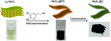 | ||
| Fig. 1 Experimental process for the preparation of MoS2@C using the self-polymerization of dopamine followed by a post carbonization process. | ||
TEM images in Fig. 2a and 2b show a few layers of MoS2@C nanosheets with a lateral size of several hundred nanometers. The carbon coating and core–shell structures are clearly shown in the high-resolution TEM image in Fig. 2c. The carbon coating layer obtained here is ∼3 nm thick on average (Fig. 2c). This core–shell structure was further investigated by the element mapping images of the energy dispersive X-ray (EDX) analysis. The carbon and nitrogen signals uniformly overlapped with the molybdenum signal of MoS2. Based on these results, a nano-sized carbon layer conformally covered the individual MoS2, resulting in ultrathin sandwich-like MoS2@C nanosheets. In addition, the MoS2@C sample was investigated using XPS (Fig. S2†). The newly appearing C 1s, N 1s and O 1s peaks of MoS2@PD indicate the successful polymerization of dopamine on the surface of the MoS2 sheet. After carbonization, the O 1s peak significantly decreased, while the N 1s peak was relatively unchanged. The chemical state of MoS2@C was further investigated by high resolution XPS (Fig. S3†). Observation of Mo 3d spectra showed two prominent peaks at 230.8 and 233.2 eV for Mo4+ 3d5/2 and Mo4+ 3d3/2, respectively.26,27 The C 1s spectrum of MoS2@C exhibited a strong and sharp peak of C–C (284.8 eV) with the weak peaks of C–N (286.2 eV) and C![[double bond, length as m-dash]](https://www.rsc.org/images/entities/char_e001.gif) O (287.8 eV). In the N 1S spectrum, two dominant peaks at 397.8 and 400.8 eV are assigned to pyridinic N and graphitic N, respectively.28 The nitrogen content is 2.6% of the elements on the surface of MoS2@C. In addition, the TGA results show 6.5 wt% of carbon on MoS2@C (Fig. S4†). This N-doped carbon resulting from the carbonization of polydopamine is beneficial for Li+ storage due to the carbon layer's facilitated electrical conductivity and the charge transfer at the interface.29
O (287.8 eV). In the N 1S spectrum, two dominant peaks at 397.8 and 400.8 eV are assigned to pyridinic N and graphitic N, respectively.28 The nitrogen content is 2.6% of the elements on the surface of MoS2@C. In addition, the TGA results show 6.5 wt% of carbon on MoS2@C (Fig. S4†). This N-doped carbon resulting from the carbonization of polydopamine is beneficial for Li+ storage due to the carbon layer's facilitated electrical conductivity and the charge transfer at the interface.29
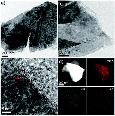 | ||
| Fig. 2 (a) and (b) TEM images of MoS2@C. (c) HR-TEM image of MoS2@C. (d) HAADF-STEM image of MoS2@C with EDX mapping of Mo, N and C. | ||
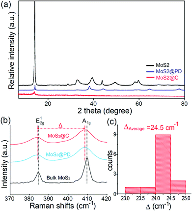
As expected, this thin and conformal coating effectively prevented the aggregation and restacking of MoS2 sheets. This was confirmed by XRD data (Fig. 3a). The prominent and strong intensity of the (002) peak corresponding to a d-spacing of 0.62 nm for pristine MoS2 becomes very weak after PD coating and carbonization.25 When observing Raman spectra (Fig. 3b and 3c), two prominent peaks of bulk MoS2 at 384.6 and 409.9 cm−1 appeared, corresponding to the E12g and A1g modes of the hexagonal MoS2 crystal, respectively.30,31 The E12g mode involves the in-layer displacement of Mo and S atoms, while the A1g mode involves the out-of-layer symmetric displacements of S atoms along the c axis.30,31 In particular, the difference between the frequencies (Δ) of the A1g and E12g modes is known to be an indicator of the number of layers.32 This value was estimated to be ∼24.3 cm−1 for MoS2@PD and ∼24.2 cm−1 for MoS2@C by measuring the Raman spectra of several independent MoS2 nanosheets. This frequency difference indicates that the MoS2@C is less than 4 layers thick.30,31 In addition, two other peaks at ∼1372 and ∼1587 cm−1, which are related to the D and G bands of carbon, were observed in both samples (Fig. S5†).33 The higher intensity ratio of ID/IG for MoS2@C compared to MoS2@PD is attributed to the increase in microcrystalline graphitic carbon through pyrolysis in the inert atmosphere.34
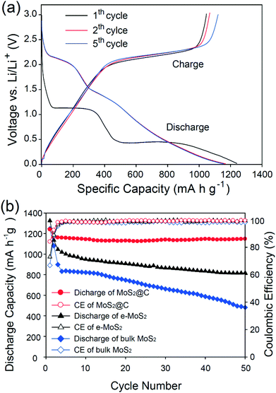
The electrochemical performance of MoS2@C was evaluated by preparing coin-type half cells (Fig. 4). During the first discharge, MoS2@C measured at 100 mA g−1 exhibited two prominent potential plateaus at approximately 1.1 V and 0.45 V, as shown in Fig. 4a. These are attributed to the phase transformation based on the following reactions (eqn (1) and (2)):13
| MoS2 + xLi+ + xe− → LixMoS2 | (1) |
| LixMoS2 + 4Li+ + 4e− → 2Li2S + Mo | (2) |
The first potential profiles are consistent with those of other MoS2 and MoS2–carbon composite anodes previously studied.11,14,32,35 The first discharge and charge capacities are 1239 and 1046 mA h g−1, respectively. Based on these values, the first Coulombic efficiency (CE) was calculated to be 84%, which is higher than those of most of the other reported MoS2-based anodes.14,36,37 This indicates that the carbon coating induces the stable formation of SEI layers during the first cycle.38 After the first cycle, the potential profiles for the 2nd and 3rd processes overlap a great deal and are followed by the reaction:13
| MoS2 + 4Li ↔ Mo + 2Li2S | (3) |
In the following cycles, a new potential plateau at around 2.1 V appeared, which is indicative of the formation of sulfur-containing substances.39,40 The unique structure of MoS2@C enabled it to have a stable cycling performance as an anode for a lithium ion battery. Fig. 4b shows specific capacity as a function of the cycle number over 50 cycles. To demonstrate the superior cycling stability of MoS2@C, exfoliated MoS2 (e-MoS2) alone and bulk MoS2 were also tested under the identical conditions of MoS2@C. When measured at a rate of 100 mA g−1, MoS2@C shows much higher specific capacities than those of e-MoS2 and MoS2 during battery cycling. After 50 cycles, the MoS2@C had a 98% (= 1147 mA h g−1) capacity retention based on a second discharge cycle. In contrast, e-MoS2 and MoS2 had the inferior cycling performances of 72% and 44%, respectively.
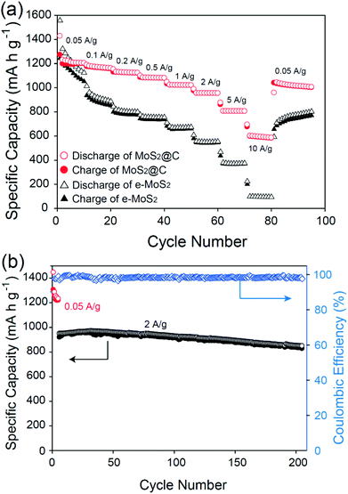
Furthermore, MoS2@C had a better rate capability than e-MoS2 and MoS2 when increasing the charge–discharge rates from 0.05 to 10 A g−1. All of the obtained capacities for MoS2@C and MoS2 were plotted with the applied current densities, as shown in Fig. 5a. MoS2@C exhibits a decent discharge capacity retention that is continuously higher than that of e-MoS2. Even when increasing the cycling rate up to 10 A g−1, 48% of the original capacity was maintained. This remaining capacity of 597 mA h g−1 was still higher than the theoretical capacity of commercial graphite (372 mA h g−1). The retention value is also higher than those of other reported MoS2-based anodes tested at even lower rates, including MoS2–carbon nanotube composites13 and MoS2–polymer–graphene nanocomposites.10 Moreover, when the current rate was finally returned to 0.05 A g−1 after a total of 80 cycles, an 85% retention of the initial capacity was still recoverable. The outstanding cycling performance of MoS2@C was further demonstrated by cycling at a high rate of 2 A g−1. A high retention value (89%) of the original capacity after 200 cycles was still maintained. This value is higher than those of other reported MoS2-based materials tested at even lower rates, including graphene-like MoS2 nanoplates6 and MoS2–grapheme.41
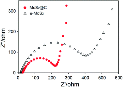
The ultrathin and conformal N-doped carbon coating of MoS2 is responsible for high capacity, high rate capability and good cycling stability. We found clear evidence of an enhanced charge transfer in MoS2@C compared to MoS2 from electrochemical impedance spectroscopy measurements. Fig. 6 shows the Nyquist plots of MoS2@C and e-MoS2. On the basis of a semicircle, MoS2@C had a lower charge transfer resistance (RCT) than that of e-MoS2. The N-doped carbon coating enabled MoS2 to improve the charge transfer at the electrode–electrolyte interface, which is responsible for reversible charge–discharge processes. At the low frequency region, a more vertical straight line was observed for MoS2@C than e-MoS2. A few layer N-doped carbon shell enabled us to improve electron conductivity and ion transfer at the interface of the electrode,23 and thus leading to the enhancement of Li+ diffusion which is responsible for the more vertical line of MoS2@C than e-MoS2. Moreover, the N-doped carbon coating enabled us to maintain the exfoliated MoS2 sheets in an ultrathin carbon shell, thus leading to the high surface area. N2 adsorption–desorption measurements provided a BET surface area of 276.8 m2 g−1 for MoS2@C, which is five-fold higher than that of bulk MoS2 (56.2 m2 g−1) and is also higher than exfoliated MoS2 (198.5 m2 g−1). Therefore, an MoS2 core embedded in an ultrathin carbon shell with a high surface area efficiently opens a reaction area where electrons can reach in all directions and meet with the inserted Li+ ions, thereby enhancing good rate and cycling performances.
Conclusions
We developed a versatile and simple method to prepare an effective core–shell structure of MoS2@C through simultaneous PD coating and carbonization processes. The surface modification of polydopamine enabled the re-stacking of MoS2 to be effectively prevented, thus leading to a high surface area. In addition, N-doped carbon coated on the surface of MoS2@C is beneficial for the transport of electrons over electrode materials, which can improve the electrochemical properties. The resultant MoS2@C was applied to the anodes for lithium ion cells and showed a specific capacitance as high as 1239 mA h g−1, a high rate capability at a high current rate of 10 A g−1 while retaining 597 mA h g−1, and a good cycle stability over 200 cycles at a high current rate of 2 A g−1. This solution-based approach is a simple and scalable method and could thus be readily applicable to other metal sulfide-based energy storage and conversion applications.Acknowledgements
This work was supported by the National Research Foundation of Korea (NRF) grant funded by the Ministry of Science, ICT and Future Planning of Korea (MSIP), No. 2010-C1AAA001-0029018 and No. 2014R1A5A2010008. The authors would also like to acknowledge BioNano Health-Guard Research Center funded by MSIP of Korea as Global Frontier Project (grant number H-GUARD_2013M3A6B2078945).Notes and references
- N.-S. Choi, Z. Chen, S. A. Freunberger, X. Ji, Y.-K. Sun, K. Amine, G. Yushin, L. F. Nazar, J. Cho and P. G. Bruce, Angew. Chem., Int. Ed., 2012, 51, 9994 CrossRef CAS PubMed.
- H. Wu, G. Chan, J. W. Choi, I. Ryu, Y. Yao, M. T. McDowell, S. W. Lee, A. Jackson, Y. Yang, L. Hu and Y. Cui, Nat. Nanotechnol., 2012, 7, 310 CrossRef CAS PubMed.
- F. Cheng, J. Liang, Z. Tao and J. Chen, Adv. Mater., 2011, 23, 1695 CrossRef CAS PubMed.
- M.-R. Gao, Y.-F. Xu, J. Jiang and S.-H. Yu, Chem. Soc. Rev., 2013, 42, 2986 RSC.
- L. Yang, S. Wang, J. Mao, J. Deng, Q. Gao, Y. Tang and O. G. Schmidt, Adv. Mater., 2013, 25, 1180 CrossRef CAS PubMed.
- H. Hwang, H. Kim and J. Cho, Nano Lett., 2011, 11, 4826 CrossRef CAS PubMed.
- H. Liu, D. Su, R. Zhou, B. Sun, G. Wang and S. Z. Qiao, Adv. Energy Mater., 2012, 2, 970 CrossRef CAS.
- R. Dominko, D. Arčon, A. Mrzel, A. Zorko, P. Cevc, P. Venturini, M. Gaberscek, M. Remskar and D. Mihailovic, Adv. Mater., 2002, 14, 1531 CrossRef CAS.
- G. Du, Z. Guo, S. Wang, R. Zeng, Z. Chen and H. Liu, Chem. Commun., 2010, 46, 1106 RSC.
- J. Xiao, X. Wang, X.-Q. Yang, S. Xun, G. Liu, P. K. Koech, J. Liu and J. P. Lemmon, Adv. Funct. Mater., 2011, 21, 2840 CrossRef CAS.
- K. Chang and W. Chen, ACS Nano, 2011, 5, 4720 CrossRef CAS PubMed.
- K. Chang, D. Geng, X. Li, J. Yang, Y. Tang, M. Cai, R. Li and X. Sun, Adv. Energy Mater., 2013, 3, 839 CrossRef CAS.
- J.-Z. Wang, L. Lu, M. Lotya, J. N. Coleman, S.-L. Chou, H.-K. Liu, A. I. Minett and J. Chen, Adv. Energy Mater., 2013, 3, 798 CrossRef CAS.
- X. Zhou, L.-J. Wan and Y.-G. Guo, Nanoscale, 2012, 4, 5868 RSC.
- J. P. Lemmon and M. M. Lerner, Chem. Mater., 1994, 6, 207 CrossRef CAS.
- J. Xiao, D. Choi, L. Cosimbescu, P. Koech, J. Liu and J. P. Lemmon, Chem. Mater., 2010, 22, 4522 CrossRef CAS.
- H. Lee, S. M. Dellatore, W. M. Miller and P. B. Messersmith, Science, 2007, 318, 426 CrossRef CAS PubMed.
- J. H. Waite, Nat. Mater., 2008, 7, 8 CrossRef CAS PubMed.
- M.-H. Ryou, Y. M. Lee, J.-K. Park and J. W. Choi, Adv. Mater., 2011, 23, 3066 CrossRef CAS PubMed.
- M.-H. Ryou, J. Kim, I. Lee, S. Kim, Y. K. Jeong, S. Hong, J. H. Ryu, T.-S. Kim, J.-K. Park, H. Lee and J. W. Choi, Adv. Mater., 2013, 25, 1571 CrossRef CAS PubMed.
- S. M. Kang, M.-H. Ryou, J. W. Choi and H. Lee, Chem. Mater., 2012, 24, 3481 CrossRef CAS.
- R. Liu, S. M. Mahurin, C. Li, R. R. Unocic, J. C. Idrobo, H. Gao, S. J. Pennycook and S. Dai, Angew. Chem., Int. Ed., 2011, 50, 6799 CrossRef CAS PubMed.
- C. Lei, F. Han, D. Li, W.-C. Li, Q. Sun, X.-Q. Zhang and A.-H. Lu, Nanoscale, 2013, 5, 1168 RSC.
- H. Li, L. Shen, K. Yin, J. Ji, J. Wang, X. Wang and X. Zhang, J. Mater. Chem. A, 2013, 1, 7270 CAS.
- G. Cetnarowski and G. W. Leach, Langmuir, 2006, 22, 8995 CrossRef CAS PubMed.
- J. Zheng, H. Zhang, S. Dong, Y. Liu, C. T. Nai, H. S. Shin, H. Y. Jeong, B. Liu and K. P. Loh, Nat. Commun., 2013, 5, 2995 Search PubMed.
- D. H. Youn, J.-W. Jang, J. Y. Kim, J. S. Jang, S. H. Choi and J. S. Lee, Sci. Rep., 2014, 4, 5492 Search PubMed.
- H. Peng, Z. Mo, S. Liao, H. Liang, L. Yang, F. Luo, H. Song, Y. Zhong and B. Zhang, Sci. Rep., 2013, 3, 1765 Search PubMed.
- Z. Ding, L. Zhao, L. Suo, Y. Jiao, S. Meng, Y.-S. Hu, Z. Wang and L. Chen, Phys. Chem. Chem. Phys., 2011, 13, 15127 RSC.
- H. Li, Q. Zhang, C. C. R. Yap, B. K. Tay, T. H. T. Edwin, A. Olivier and D. Baillargeat, Adv. Funct. Mater., 2012, 22, 1385 CrossRef CAS.
- X. Huang, Z. Zeng and H. Zhang, Chem. Soc. Rev., 2013, 42, 1934 RSC.
- K. F. Mak, C. Lee, J. Hone, J. Shan and T. F. Heinz, Phys. Rev. Lett., 2010, 105, 136805 CrossRef.
- H. F. Xiang, Z. D. Li, K. Xie, J. Z. Jiang, J. J. Chen, P. C. Lian, J. S. Wu, Y. Yu and H. H. Wang, RSC Adv., 2012, 2, 6792 RSC.
- Z. Wang, T. Chen, W. Chen, K. Chang, L. Ma, G. Huang, D. Chen and J. Y. Lee, J. Mater. Chem. A, 2013, 1, 2202 CAS.
- K. Chang and W. Chen, Chem. Commun., 2011, 47, 4252 RSC.
- P.-P. Wang, H. Sun, Y. Ji, W. Li and X. Wang, Adv. Mater., 2014, 26, 964 CrossRef CAS PubMed.
- K. Bindumadhavan, S. K. Srivastava and S. Mahanty, Chem. Commun., 2013, 49, 1823 RSC.
- N. Liu, H. Wu, M. T. McDowell, Y. Yao, C. Wang and Y. Cui, Nano Lett., 2012, 12, 3315 CrossRef CAS PubMed.
- J. Wang, J. Yang, C. Wan, K. Du, J. Xie and N. Xu, Adv. Funct. Mater., 2003, 13, 487 CrossRef CAS.
- J. Wang, J. Chen, K. Konstantinov, L. Zhao, S. H. Ng, G. X. Wang, Z. P. Guo and H. K. Liu, Electrochim. Acta, 2006, 51, 4634 CrossRef CAS PubMed.
- G. Huang, T. Chen, W. Chen, Z. Wang, K. Chang, L. Ma, F. Huang, D. Chen and J. Y. Lee, Small, 2013, 21, 3693 CrossRef PubMed.
Footnote |
| † Electronic supplementary information (ESI) available: TEM images, XPS, TGA and Raman spectra. See DOI: 10.1039/c4nr06215a |
| This journal is © The Royal Society of Chemistry 2015 |

