 Open Access Article
Creative Commons Attribution 3.0 Unported Licence
Centrifugal step emulsification applied for absolute quantification of nucleic acids by digital droplet RPA†
Friedrich
Schuler
*ab,
Frank
Schwemmer
b,
Martin
Trotter
a,
Simon
Wadle
b,
Roland
Zengerle
abc,
Felix
von Stetten
ab and
Nils
Paust
ab
aHahn-Schickard, Georges-Koehler-Allee 103, 79110 Freiburg, Germany. E-mail: Friedrich.Schuler@Hahn-Schickard.de
bLaboratory for MEMS Applications, IMTEK – Department of Microsystems Engineering, University of Freiburg, Georges-Koehler-Allee 103, 79110 Freiburg, Germany
cBIOSS – Centre for Biological Signalling Studies, University of Freiburg, Freiburg, Germany
First published on 23rd April 2015
Abstract
Aqueous microdroplets provide miniaturized reaction compartments for numerous chemical, biochemical or pharmaceutical applications. We introduce centrifugal step emulsification for the fast and easy production of monodisperse droplets. Homogenous droplets with pre-selectable diameters in a range from 120 μm to 170 μm were generated with coefficients of variation of 2–4% and zero run-in time or dead volume. The droplet diameter depends on the nozzle geometry (depth, width, and step size) and interfacial tensions only. Droplet size is demonstrated to be independent of the dispersed phase flow rate between 0.01 and 1 μl s−1, proving the robustness of the centrifugal approach. Centrifugal step emulsification can easily be combined with existing centrifugal microfluidic unit operations, is compatible to scalable manufacturing technologies such as thermoforming or injection moulding and enables fast emulsification (>500 droplets per second and nozzle) with minimal handling effort (2–3 pipetting steps). The centrifugal microfluidic droplet generation was used to perform the first digital droplet recombinase polymerase amplification (ddRPA). It was used for absolute quantification of Listeria monocytogenes DNA concentration standards with a total analysis time below 30 min. Compared to digital droplet polymerase chain reaction (ddPCR), with processing times of about 2 hours, the overall processing time of digital analysis was reduced by more than a factor of 4.
Introduction
One of the most important applications of aqueous droplets is the use in digital amplification techniques such as digital PCR (dPCR).1 Digital PCR offers many advantages over the bulk reaction,2 such as absolute quantification without the need for standards and much higher accuracy and sensitivity. To perform digital amplification, the reaction mixture needs to be digitized into a number of compartments that are usually much higher than the expected number of target molecules in the sample. For evaluation of the result, all compartments are assumed to be of the same size. Therefore, a large number of monodisperse droplets are needed for droplet digital amplification.The two most common techniques for production of homogeneous droplets used in these systems are T-junctions3–8 and flow focusing.9–11 T-junction devices consist of 2 inlet channels joined perpendicularly. At the junction, a flow of continuous phase shears off droplets of the dispersed phase. Flow focusing devices consist of 3 inlet channels. The dispersed liquid is flowing through one channel that is intercepted by two other channels delivering the homogeneous phase to the emulsion. The joined flow passes through a constriction at which droplets are generated. The production of droplets using a flow focusing system has also been shown in centrifugal microfluidic setups.12 However, to ensure a homogeneous droplet size distribution, all of these established systems require extremely precise control over the flow rate.13–15 Moreover, homogeneous droplet production can only be ensured after an initial run-in time (seconds to minutes) to equilibrate the flow of dispersed phase and continuous phase in all of the channels.16–18 At the end of each run, substantial amounts of the fluid remain trapped in the tubing to avoid droplet inhomogeneities due to pressure changes in the run-out phase. These significant dead volumes of the dispersed phase waste precious sample material.19
Run-in time and thus dead volume can be reduced by step emulsification. Here, droplet break-up is dominated by the abrupt change in capillary pressure as droplets are formed at a backward facing step.20–25 Only one channel is required for introduction of both the oil phase and the aqueous phase. In addition, this principle is less sensitive to pressure and flow rate fluctuations ensuring a more robust monodispersity. Moreover, the design, production and operation of step emulsification systems are simple and robust since the size of only one microchannel and the flow of only one liquid need to be controlled26,27 as opposed to T-junction and co-flow systems.28 For a wide range of flow rates, the diameter of droplets is independent of pressure and flow rate. However, a disadvantage of step emulsification lies in its limited throughput due to droplet accumulation at the nozzle (i.e. the position at which the reagent introduction channels meets the backward facing step).29 To transport the formed droplets away from the nozzle, an additional flow of continuous phase perpendicular to the nozzle30 has been proposed. Alternatively, tapered channels have been used to produce droplets27 of homogeneous diameter and to transport the droplets away from the nozzle employing the principle of surface tension-driven transport of isolated compartments in multiphase systems.31,32
In this work, we present centrifugal step emulsification featuring dead volume free production of monodisperse droplets combined with adjustable and high droplet generation frequencies and robust and easy handling. Centrifugal step emulsification enables a straightforward transport of the droplets away from the nozzle due to density differences and the centrifugal gravity field. Generation frequencies of monodisperse droplets can be adjusted and tuned up to high frequencies in an easy manner. In contrast to co-flow,29,33 parallelization is simple since only the flow of the dispersed phase needs to be controlled and flow control for all parallel nozzles is achieved by adjusting the rotational speed.
The droplets are used to perform the first digital droplet recombinase polymerase amplification (RPA). RPA is a DNA amplification technique that works at a constant temperature of ~39 °C, needs no thermal cycles and is much faster than PCR taking only 15–30 minutes to complete the reaction. However, no universal strategy for quantitative measurements using RPA has been presented so far. This makes digital droplet RPA an attractive candidate since it allows for absolute quantification of nucleic acids.
For ddPCR, the sample/PCR mix is usually compartmentalized into a number of droplets after which a hot-start is performed to initiate amplification. By doing so, amplification of the targets in the bulk before droplet formation is avoided. In contrast, isothermal methods such as RPA34 cannot be triggered by a hot-start but will start amplification when Mg2+ is added. Therefore, after addition of Mg2+, fast droplet production and handling are mandatory to avoid amplification in the bulk. The high throughput centrifugal step emulsification thus provides an important enabling technology for dead volume free digital droplet RPA (ddRPA), used here for absolute quantification of L. monocytogenes DNA.
Experimental
Microfluidic disks were fabricated by micromilling in polymethyl methacrylate (PMMA) (Maertin, Freiburg, Germany) using a Kern Evo (Kern Micro- und Feinwerktechnik GmbH & Co. KG, Eschenlohe, Germany). Fabrication of the disks was performed by the Lab-on-a-Chip Design & Foundry Service of Hahn-Schickard. After milling, all structures were measured using a Zeiss AX10 microscope equipped with an AxioCam ICc1 and an Imager M2m (Zeiss, Jena, Germany). Channel depth was measured by adjusting the height of the stage, thereby focussing on the bottom of the channel and the top of the substrate, respectively. The difference in height of the stage was measured electronically. Subsequently, the disks were sealed using pressure-sensitive adhesive foil (#900 320, HJ Bioanalytik, Erkelenz, Germany). To ensure reproducible sealing parameters, a modified PCS 30 lamination tool (Jakob Weiß & Söhne, Sinsheim, Germany) was used. All structures with large shallow chambers contained pillars to support the sealing foil. The disks were processed using a “LabDisk player” (for photographic image, see Fig. S1†) which is a centrifugal setup custom built by Qiagen Lake Constance (ESE GmbH, Stockach, Germany). It can spin polymer disks with tight control of spinning frequency and acceleration. Moreover, the LabDisk player can heat and cool the disk while rotating, and microscopic images can be acquired under rotation via a stroboscopic setup.35 For fluorescence imaging, a LaVision Bioanalyzer (4F/4S, LaVision BioTec GmbH, Bielefeld, Germany) with an integration time of 150 ms was used. A mercury-vapor lamp was used as light source, and excitation and emission light was filtered at 482 nm and 536 nm, respectively. Image processing was performed using ImageJ36 and Matlab 2013 (Mathworks, Natick, USA). The images from the stroboscopic setup were used for comparison of droplet diameter. The contrast was increased for the images, and a Matlab routine for automated droplet recognition and diameter measurement was used to avoid manual bias. The coefficient of variation (CV) was calculated as the ratio of standard deviation and average value. For all experiments, Novec7500 (Iolitec, Heilbronn, Germany) which is equivalent to HFE7500 was used as the continuous oil phase. As surfactant, Picosurf-1 (Dolomite, Royston, UK) was used. We want to thank Dolomite for a generous gift of surfactants for our experiments. Different concentrations of surfactant were evaluated with an optimum of 2% w/v used in all experiments. For fluidic evaluation, the aqueous phase was 2× Finnzymes DyNAmo Flash Probe qPCR Kit master mix (Thermo Fisher Scientific, Waltham, USA) diluted 1![[thin space (1/6-em)]](https://www.rsc.org/images/entities/char_2009.gif) :
:![[thin space (1/6-em)]](https://www.rsc.org/images/entities/char_2009.gif) 1 with DNAse/RNAse free water (Thermo Fisher Scientific, Waltham, USA) if not mentioned otherwise. The interfacial tension was measured to be 3.9 ± 0.1 mN m−1 by the inverted pendant drop method using a modified OCA 15 Plus (Dataphysics, Filderstad, Germany) and custom image analysis. All RPA reactions were performed using RPA nfo Kit (TwistDx, Cambridge, UK) according to the manufacturer's protocol with exception of the addition of Mg2+. Mg2+ solution was prepared separately on ice and added to the ice-cold reaction mixture in a last step directly before emulsification. For the digital droplet RPA, L. monocytogenes DNA (Certified Reference Material IRMM-447 (strain 4B, NCTC 11994), Brussels, Belgium) was used in concentrations given. Dilution was performed in LoBind tubes (Eppendorf, Hamburg, Germany) using a dilution buffer containing 10 mM Tris HCl (pH 8.0), 0.1 mM EDTA and 1 ng μl−1 human genomic DNA. The primers and probes used were those from the L. monocytogenes kit from TwistDx (Cambridge, UK). The sequences are given as follows:
1 with DNAse/RNAse free water (Thermo Fisher Scientific, Waltham, USA) if not mentioned otherwise. The interfacial tension was measured to be 3.9 ± 0.1 mN m−1 by the inverted pendant drop method using a modified OCA 15 Plus (Dataphysics, Filderstad, Germany) and custom image analysis. All RPA reactions were performed using RPA nfo Kit (TwistDx, Cambridge, UK) according to the manufacturer's protocol with exception of the addition of Mg2+. Mg2+ solution was prepared separately on ice and added to the ice-cold reaction mixture in a last step directly before emulsification. For the digital droplet RPA, L. monocytogenes DNA (Certified Reference Material IRMM-447 (strain 4B, NCTC 11994), Brussels, Belgium) was used in concentrations given. Dilution was performed in LoBind tubes (Eppendorf, Hamburg, Germany) using a dilution buffer containing 10 mM Tris HCl (pH 8.0), 0.1 mM EDTA and 1 ng μl−1 human genomic DNA. The primers and probes used were those from the L. monocytogenes kit from TwistDx (Cambridge, UK). The sequences are given as follows:
Forward primer (all in 5′ → 3′ direction): CGCCTGCAAGTCCTAAGACGCCAATCGAAAAGAAAC
Reverse primer: CTGCATCTCCGTGGTATACTAATACATTGTTTTTA
Probe: CGAAAAGAAACACGCGGATGAAATCGATAAG[FAM][THF][BHQ-1]ATACAAGGATTGGA
After emulsification, the droplets were heated to 39 °C for 25 min using the LabDisk player.
As a reference for absolute quantification, digital droplet PCR experiments were performed according to Bio-Rad protocols using Bio-Rad reagents (oil and master mix) (Bio-Rad, Munich, Germany). The primers and probes used are given as follows:
Forward primer: TTCAATTTCATCCATGGCAC at 300 nM final concentration
Reverse primer: CTTTGTAACCTTTTCTTGGC at 300 nM final concentration
Probe: [FAM]ACGCCAATCGAAAAGAAACACGC[BHQ-1] at 200 nM final concentration
The cycling protocol consisted of 95 °C for 10 min and 40 cycles of 30 s at 95 °C and 60 s at 60 °C followed by 98 °C for 10 min conducted using a Bio-Rad C1000 Touch Thermal Cycler (Bio-Rad, Munich, Germany).
Results and discussion
Droplet generation
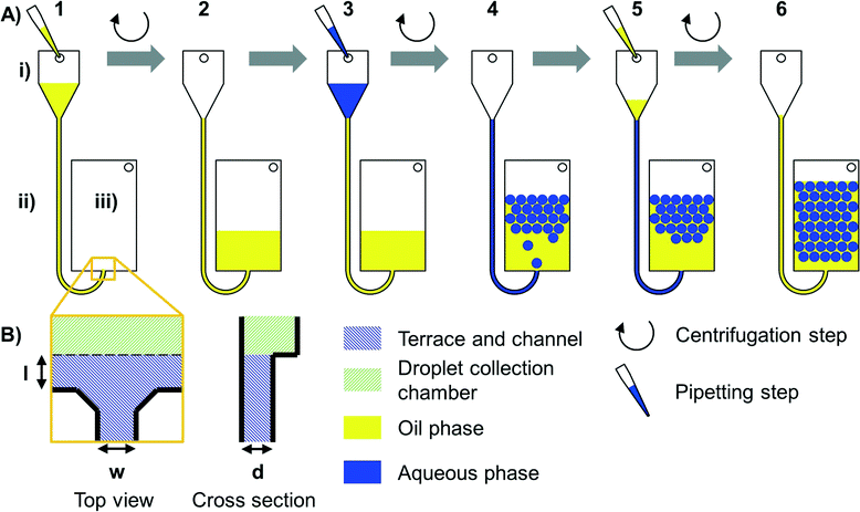
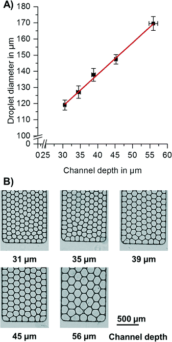
Centrifugal forces were used to control the liquid flow (see Fig. 1) in the step emulsification process (for details, see Fig. S2†). When the aqueous phase reaches the nozzle, a hydrostatic pressure of the aqueous medium and the previously introduced oil at the nozzle can be calculated from the spinning frequency, radii and liquid densities. The overpressure of the aqueous medium compared to oil (Δp = paqueous phase − poil phase) is the driving force for the step emulsification-based droplet generation.To provide droplets of different diameters, the channel depth was varied (for variation of terrace length, see ESI† “Process of step emulsification and influence of terrace length” and Fig. S3 and S4†). Since the channels had a cross section with aspect ratios <1, the depth is the droplet diameter limiting factor. For quantification of droplet diameters, pictures of the droplets were taken directly after break-up. As can be seen in Fig. 2, the droplet diameter linearly increases with the depth of the channel. This finding is in good accordance with the basic theory of step emulsification in the absence of centrifugal forces.37 It thus indicates that for the studied configuration, droplet size is exclusively determined by nozzle geometries and not influenced by the artificial centrifugal gravity field. The diameter of the produced droplets had a coefficient of variation (CV) of 2–4%, independent of the diameters generated by the different channel depths.
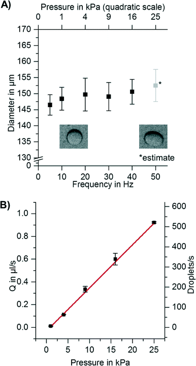
Since a short time (0.5–5 s) is needed to accelerate the disk, some droplets might already be formed before the final spinning frequency is reached and thus are formed at lower overpressures Δp at the nozzle. This might lead to inhomogeneity in droplet diameter. In addition to that, levels of liquids in the channel and/or chamber change during the experiment and also lead to varying hydrostatic overpressures. It is therefore important to measure the dependency of droplet diameter on spinning frequency and on overpressure Δp. As illustrated in Fig. 3A, the droplet diameter does not depend on the overpressure Δp over nearly two orders of magnitude. Thus, the acceleration phase or changes in the filling level of the inlet chamber will not affect the droplet diameters.
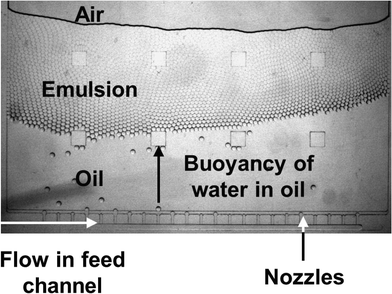
To increase the throughput of the system, the spinning frequency was increased while droplet generation frequency was measured. As expected, the droplet generation frequency increased linearly with the overpressure at the nozzle (Δp) (see Fig. 3B). It was thereby possible to increase the droplet production rate from <1 droplet s−1 to >500 droplets s−1 per nozzle, while maintaining monodispersity. All of these experiments were performed using one nozzle per setup. However, for centrifugal step emulsification, it is straightforward to increase the number of nozzles (as can be seen from Fig. S5 and in the ESI† “Parallelization and high throughput”). The flow of dispersed phase in all channels can be easily controlled by the spinning frequency. In addition, the formed droplets are quickly removed from the nozzle by buoyancy within the centrifugal gravity field.
To increase throughput, multiple nozzles branching off from a shared feed channel were designed in a way that the fluidic resistance of the feed channel was much lower than that of the nozzles (i.e. the cross section of the feed channel was larger than that of a single nozzle, see Table S1†). Homogeneous droplet production (CV = 2–4%) could be achieved (see Fig. 4 and S6A†). For a video of droplet production in real time, see Movie S1.†
At high rotational frequencies of 20 Hz, the droplets are transported away from the nozzle very fast, while the continuous phase remains at the nozzle. Emulsification with very high volume fractions of dispersed phase of up to 97.2% could be performed exceeding already high literature values of up to 96%.3,38 This enables the production of gel emulsions with extremely low consumption of surrounding phase.
Digital droplet RPA for absolute quantification of L. monocytogenes
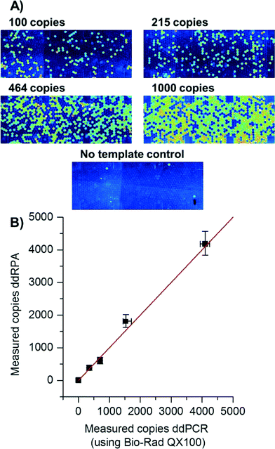
Recently, digital experiments with isothermal amplification have been shown,39–43 some mentioning RPA in droplets.44 Many isothermal amplification techniques cannot be simply triggered using a “hot-start” which is established in PCR. Instead, the reaction mixture is prepared without the addition of co-factors (e.g. Mg2+) so that the reaction cannot start. Upon addition of the co-factor, the reaction begins to proceed, sometimes even at room temperature. In order to disable amplification between addition of Mg2+ solution to the Mg2+-deprived RPA reaction mixture and droplet generation, reagents were pre-cooled to 0 °C during preparation. After the Mg2+ solution was added to the RPA reaction mixture, droplet production was completed in less than 15 seconds, allowing very little time for the solution to warm up or start amplification.In contrast to previously performed digital RPA reactions on the SlipChip in distinct cavities that are brought together by a sliding motion41 here the fast production of droplets enabled by centrifugal step emulsification (<15 s for the whole process) was used to perform the first digital droplet RPA (ddRPA). The number of copies measured with ddRPA was concordant to the number of copies measured with digital droplet PCR (ddPCR), as can be seen in Fig. 5. Thus, it was possible to count the number of individual copies of L. monocytogenes DNA with ddRPA. This is an interesting technique for monitoring of possible contaminations in foodstuffs.45 The signal increase during the reaction was good (5.5-fold) providing a clear distinguishability between positive and negative droplets. Overall processing was less than 30 min which is a 4-fold decrease compared to ddPCR.
Conclusion
We presented centrifugal step emulsification for dead volume free emulsification. The structure used here is easy to use (2–3 pipetting steps required) and works without any pumps or tubing. It consists of only one inlet chamber and one channel connected to a chamber by a nozzle. The droplet production proceeds with low CV (2–4%), and droplet diameters do not change over ~100-fold increase in pressure. For this reason, neither flow rate nor pressure needs to be tightly controlled. Compared to other droplet generation systems,33,46 the throughput of the system per nozzle (500 droplets s−1) was high and parallelization straightforward. Fabrication from thermoplastic polymers without any surface coatings renders the structure an attractive candidate for low cost mass production by injection moulding.The microfluidic structure presented here was used for digital droplet RPA (ddRPA) of L. monocytogenes. The absolute quantification of L. monocytogenes in food production is important to monitor compliance of L. monocytogenes concentration with current regulation.45 For the processing of real food samples, additional steps such as homogenization/liquefaction, filtering and/or DNA extraction would be needed. In contrast to commonly used digital droplet PCR (ddPCR) systems, the time-to-result was reduced by a factor of 4 from 2 h to 30 min. The reduced time-to-result is especially important for critical clinical applications such as sepsis. No thermal cycling is needed to perform RPA, thus offering the potential for very easy and cheap digital amplification. Currently available droplet digital systems take considerable time to produce the droplets which leads to amplification in the bulk. Thus, they offer no possibility to perform ddRPA. In contrast, the platform presented here is open to many DNA amplification techniques such as RPA, PCR, rolling circle amplification (RCA) and loop-mediated isothermal amplification (LAMP). The dense packing of droplets saves space compared to digital RPA in cavities separated by solid matter. Since droplet production, amplification of DNA and readout all take place in the same chamber, the microfluidic structure is easy to design and adapt and requires little space.
In future, the centrifugal step emulsification enables the integration of digital droplet amplification techniques into centrifugal microfluidic analysis systems. By combining the emulsification with DNA purification,47–49 fully integrated sample-to-digital-answer disposables may be realized. Fluids such as oil and reaction buffers can be pre-stored on the disk using, e.g., stick packs.50 The sample preparation and reagent pre-storage could then be integrated with structures for pumping51–53 and structures for (timed) valving54–56 to provide the DNA mixture at the centre of the disk as a starting point for emulsification. Readout may be performed with cheap fluorescence measurement systems such as smartphone-based devices.57 Altogether, highly integrated centrifugal systems for digital nucleic acid analysis may be realized.
Other applications for the droplet generation include the production of monodisperse particles for controlled release of medical compounds58,59 and the digital counting of colony forming units (CFUs).60
Acknowledgements
We gratefully acknowledge financial support from EU Framework 7 project “ANGELab” (#317635). We want to thank Michael Lehnert and Marcel Geltman for helpful discussions. We furthermore want to thank the Lab-on-a-Chip Design & Foundry Service of Hahn-Schickard for manufacturing the readout chips, as well as Oliver Barth and Benjamin Rutschinski for helpful discussion. We like to thank Matthew Forrest from TwistDx for helpful discussion and providing the sequences of the RPA oligos. We like to thank Marie Follo and her team at Core Facility of University Hospital of Freiburg for performing digital droplet PCR experiments.References
- B. Vogelstein and K. W. Kinzler, Proc. Natl. Acad. Sci. U. S. A., 1999, 96, 9236–9241 CrossRef CAS.
- M. T. Guo, A. Rotem, J. A. Heyman and D. A. Weitz, Lab Chip, 2012, 12, 2146–2155 RSC.
- R. Seemann, M. Brinkmann, T. Pfohl and S. Herminghaus, Reports on progress in physics. Physical Society (Great Britain), 2012, vol. 75, p. 016601 Search PubMed.
- G. F. Christopher and S. L. Anna, J. Phys. D: Appl. Phys., 2007, 40, R319 CrossRef CAS.
- P. Guillot and A. Colin, Phys. Rev. E: Stat., Nonlinear, Soft Matter Phys., 2005, 72 Search PubMed.
- J. H. Xu, S. W. Li, J. Tan and G. S. Luo, Microfluid. Nanofluid., 2008, 5, 711–717 CrossRef CAS.
- D. Malsch, N. Gleichmann, M. Kielpinski, G. Mayer, T. Henkel, D. Mueller, V. van Steijn, C. R. Kleijn and M. T. Kreutzer, Microfluid. Nanofluid., 2010, 8, 497–507 CrossRef CAS.
- T. Thorsen, R. W. Roberts, F. H. Arnold and S. R. Quake, Phys. Rev. Lett., 2001, 86, 4163–4166 CrossRef CAS.
- A. Gañán-Calvo, Phys. Rev. Lett., 1998, 80, 285–288 CrossRef.
- P. B. Umbanhowar, V. Prasad and D. A. Weitz, Langmuir, 2000, 16, 347–351 CrossRef CAS.
- S. L. Anna, N. Bontoux and H. A. Stone, Appl. Phys. Lett., 2003, 82, 364 CrossRef CAS PubMed.
- S. Haeberle, R. Zengerle and J. Ducrée, Microfluid. Nanofluid., 2007, 3, 65–75 CrossRef.
- W. Li, E. W. K. Young, M. Seo, Z. Nie, P. Garstecki, C. A. Simmons and E. Kumacheva, Soft Matter, 2008, 4, 258 RSC.
- W. Zeng, I. Jacobi, D. J. Beck, S. Li and H. A. Stone, Lab Chip, 2015, 15(4), 1110–1115 RSC.
- P. M. Korczyk, O. Cybulski, S. Makulska and P. Garstecki, Lab Chip, 2011, 11, 173–175 RSC.
- P. Garstecki, M. J. Fuerstman, H. A. Stone and G. M. Whitesides, Lab Chip, 2006, 6, 437–446 RSC.
- Y. Ding, X. C. Solvas and A. deMello, Analyst, 2015, 140, 414–421 RSC.
- Bio-Rad, Droplet Digital PCR Applications Guide, available at: http://www.bio-rad.com/webroot/web/pdf/lsr/literature/Bulletin_6407.pdf, accessed 23 February 2015 Search PubMed.
- M. Baker, Nat. Methods, 2012, 9, 541–544 CrossRef CAS PubMed.
- S. Sugiura, M. Nakajima, N. Kumazawa, S. Iwamoto and M. Seki, J. Phys. Chem. B, 2002, 106, 9405–9409 CrossRef CAS.
- S. Sugiura, M. Nakajima and M. Seki, Langmuir, 2002, 18, 5708–5712 CrossRef CAS.
- S. Sugiura, M. Nakajima, T. Oda, M. Satake and M. Seki, J. Colloid Interface Sci., 2004, 269, 178–185 CrossRef CAS PubMed.
- S. Sugiura, M. Nakajima and M. Seki, Langmuir, 2002, 18, 3854–3859 CrossRef CAS.
- S. Sugiura, M. Nakajima and M. Seki, Ind. Eng. Chem. Res., 2004, 43, 8233–8238 CrossRef CAS.
- S. Sugiura, M. Nakajima, K. Yamamoto, S. Iwamoto, T. Oda, M. Satake and M. Seki, J. Colloid Interface Sci., 2004, 270, 221–228 CrossRef CAS PubMed.
- R. Dangla, E. Fradet, Y. Lopez and C. N. Baroud, J. Phys. D: Appl. Phys., 2013, 46, 114003 CrossRef.
- R. Dangla, S. C. Kayi and C. N. Baroud, Proc. Natl. Acad. Sci. U. S. A., 2013, 110, 853–858 CrossRef CAS PubMed.
- A. Abate, A. Poitzsch, Y. Hwang, J. Lee, J. Czerwinska and D. Weitz, Phys. Rev. E: Stat., Nonlinear, Soft Matter Phys., 2009, 80 Search PubMed.
- K. C. van Dijke, G. Veldhuis, K. Schroën and R. M. Boom, AIChE J., 2009 Search PubMed , NA.
- S. Sugiura, M. Nakajima, S. Iwamoto and M. Seki, Langmuir, 2001, 17, 5562–5566 CrossRef CAS.
- N. Paust, C. Litterst, T. Metz, M. Eck, C. Ziegler, R. Zengerle and P. Koltay, Microfluid. Nanofluid., 2009, 7, 531–543 CrossRef CAS.
- D. Chakraborty and S. Chakraborty, Appl. Phys. Lett., 2010, 97, 234103 CrossRef PubMed.
- T. Nisisako and T. Torii, Lab Chip, 2008, 8, 287–293 RSC.
- O. Piepenburg, C. H. Williams, D. L. Stemple and N. A. Armes, PLoS Biol., 2006, 4, e204 Search PubMed.
- M. Grumann, T. Brenner, C. Beer, R. Zengerle and J. Ducrée, Rev. Sci. Instrum., 2005, 76, 025101 CrossRef PubMed.
- M. D. Abramoff, P. J. Magalhães and S. J. Ram, Biophotonics International, 2004, 11, 36–42 Search PubMed.
- E. van der Zwan, K. Schroën and R. Boom, Langmuir, 2009, 25, 7320–7327 CrossRef CAS PubMed.
- C. Priest, S. Herminghaus and R. Seemann, Appl. Phys. Lett., 2006, 88, 024106 CrossRef PubMed.
- A. Gansen, A. M. Herrick, I. K. Dimov, L. P. Lee and D. T. Chiu, Lab Chip, 2012, 12, 2247–2254 RSC.
- L. Mazutis, A. F. Araghi, O. J. Miller, J.-C. Baret, L. Frenz, A. Janoshazi, V. Taly, B. J. Miller, J. B. Hutchison, D. Link, A. D. Griffiths and M. Ryckelynck, Anal. Chem., 2009, 81, 4813–4821 CrossRef CAS PubMed.
- F. Shen, E. K. Davydova, W. Du, J. E. Kreutz, O. Piepenburg and R. F. Ismagilov, Anal. Chem., 2011, 83, 3533–3540 CrossRef CAS PubMed.
- B. Sun, F. Shen, S. E. McCalla, J. E. Kreutz, M. A. Karymov and R. F. Ismagilov, Anal. Chem., 2013, 85, 1540–1546 CrossRef CAS PubMed.
- T. D. Rane, L. Chen, H. C. Zec and T.-H. Wang, Lab Chip, 2015, 15, 776–782 RSC.
- C. J. DeJournette, J. Kim, H. Medlen, X. Li, L. J. Vincent and C. J. Easley, Anal. Chem., 2013, 85, 10556–10564 CrossRef CAS PubMed.
- European Commission, COMMISSION REGULATION (EC) No. 2073/2005 of 15 November 2005 on microbiological criteria for foodstuffs, 2005, vol. 2005 Search PubMed.
- A. C. Hatch, J. S. Fisher, A. R. Tovar, A. T. Hsieh, R. Lin, S. L. Pentoney, D. L. Yang and A. P. Lee, Lab Chip, 2011, 11, 3838–3845 RSC.
- S. Hugo, K. Land, M. Madou and H. Kido, S. Afr. J. Sci., 2014, 110, 1–7 CrossRef PubMed.
- T.-H. Kim, J. Park, C.-J. Kim and Y.-K. Cho, Anal. Chem., 2014, 86, 3841–3848 CrossRef CAS PubMed.
- B. S. Lee, Y. U. Lee, H.-S. Kim, T.-H. Kim, J. Park, J.-G. Lee, J. Kim, H. Kim, W. G. Lee and Y.-K. Cho, Lab Chip, 2011, 11, 70–78 RSC.
- T. van Oordt, Y. Barb, J. Smetana, R. Zengerle and F. von Stetten, Lab Chip, 2013, 13, 2888–2892 RSC.
- S. Zehnle, F. Schwemmer, G. Roth, F. von Stetten, R. Zengerle and N. Paust, Lab Chip, 2012, 12, 5142–5145 RSC.
- M. C. R. Kong and E. D. Salin, Anal. Chem., 2010, 82, 8039–8041 CrossRef CAS PubMed.
- M. C. R. Kong, A. P. Bouchard and E. D. Salin, Micromachines, 2012, 3, 1–9 CrossRef PubMed.
- A. LaCroix-Fralish, E. J. Templeton, E. D. Salin and C. D. Skinner, Lab Chip, 2009, 9, 3151–3154 RSC.
- H. Hwang, H.-H. Kim and Y.-K. Cho, Lab Chip, 2011, 11, 1434–1436 RSC.
- F. Schwemmer, S. Zehnle, D. Mark, F. von Stetten, R. Zengerle and N. Paust, Lab Chip, 2015, 15, 1545–1553 RSC.
- Q. Wei, H. Qi, W. Luo, D. Tseng, S. J. Ki, Z. Wan, Z. Göröcs, L. A. Bentolila, T.-T. Wu, R. Sun and A. Ozcan, ACS Nano, 2013, 7, 9147–9155 CrossRef CAS PubMed.
- Q. Xu, M. Hashimoto, T. T. Dang, T. Hoare, D. S. Kohane, G. M. Whitesides, R. Langer and D. G. Anderson, Small, 2009, 5, 1575–1581 CrossRef CAS PubMed.
- D. Ogończyk, M. Siek and P. Garstecki, Biomicrofluidics, 2011, 5, 13405 CrossRef PubMed.
- K. F. Tjhung, S. Burnham, H. Anany, M. W. Griffiths and R. Derda, Anal. Chem., 2014, 86, 5642–5648 CrossRef CAS PubMed.
Footnote |
| † Electronic supplementary information (ESI) available. See DOI: 10.1039/c5lc00291e |
| This journal is © The Royal Society of Chemistry 2015 |

