 Open Access Article
A shape-deformable and thermally stable solid-state electrolyte based on a plastic crystal composite polymer electrolyte for flexible/safer lithium-ion batteries†
Se-Hee
Kim
a,
Keun-Ho
Choi
a,
Sung-Ju
Cho
a,
Joo-Sung
Park
a,
Kuk Young
Cho
b,
Chang Kee
Lee
c,
Sang Bong
Lee
c,
Jin Kie
Shim
c and
Sang-Young
Lee
*a
aInterdisciplinary School of Green Energy, Ulsan National Institute of Science and Technology (UNIST), Ulsan, 689-798, Korea. E-mail: syleek@unist.ac.kr; Fax: +82-52-217-2019; Tel: +82-52-217-2948
bDivision of Advanced Materials Engineering, Kongju National University, Chungnam 331-717, Korea
cKorea Packaging Center, Korea Institute of Industrial Technology, Bucheon, Gyeonggido 421-742, Korea
First published on 5th March 2014
Abstract
A solid-state electrolyte with reliable electrochemical performance, mechanical robustness and safety features is strongly pursued to facilitate the progress of flexible batteries. Here, we demonstrate a shape-deformable and thermally stable plastic crystal composite polymer electrolyte (denoted as “PC-CPE”) as a new class of solid-state electrolyte to achieve this challenging goal. The PC-CPE is composed of UV (ultraviolet)-cured ethoxylated trimethylolpropane triacrylate (ETPTA) macromer/close-packed Al2O3 nanoparticles (acting as the mechanical framework) and succinonitrile-mediated plastic crystal electrolyte (serving as the ionic transport channel). This chemical/structural uniqueness of the PC-CPE brings remarkable improvement in mechanical flexibility and thermal stability, as compared to conventional carbonate-based liquid electrolytes that are fluidic and volatile. In addition, the PC-CPE precursor mixture (i.e., prior to UV irradiation) with well-adjusted rheological properties, via collaboration with a UV-assisted imprint lithography technique, produces the micropatterned PC-CPE with tunable dimensions. Notably, the cell incorporating the self-standing PC-CPE, which acts as a thermally stable electrolyte and also a separator membrane, maintains stable charge/discharge behavior even after exposure to thermal shock condition (=130 °C/0.5 h), while a control cell assembled with a carbonate-based liquid electrolyte and a polyethylene separator membrane loses electrochemical activity.
Introduction
Wearable electronic devices such as bendable smart phones, roll-up displays and patchable/implantable sensors have recently garnered a great deal of attention due to their aesthetic versatility/mobile usability that lies far beyond those accessible with conventional approaches.1–5 Lithium-ion rechargeable batteries (hereinafter, referred to as “batteries”), the most widespread portable energy storage system, are recommended as a promising power source to fulfill stringent requirements for wearable electronics. To date, most research activities on flexible batteries have focused on design and fabrication of new functional electrodes, including nanostructured electrode active materials, low-dimensional carbon nanotubes/graphene-based electrodes and non-metallic current collectors adopting conductive paper/textiles.6–14In comparison, little attention has been devoted to developing advanced electrolytes for flexible batteries. Currently commercially available liquid electrolytes ensure good electrochemical performance and benign interfacial contact with electrodes, however, their fluidic attributes cause critical limitation in battery design because separator membranes and packaging canisters with fixed dimension are essentially needed for cell assembly. In addition, the potential leakage problem of liquid electrolytes is another thorny issue that impairs electrochemical performance and also safety of cells. As a result, the use of liquid electrolytes poses a big obstacle to the realization of flexible/safe batteries with shape diversity.15–17 These challenges arising from the use of liquid electrolytes strongly push us to search for alternative solid-state electrolytes with full-fledged characteristics suitable for flexible battery applications.
Recently, our group reported the bendable and shape-conformable composite gel polymer electrolyte consisting of a UV-crosslinked polymer, carbonate-based liquid electrolyte and nanoparticles.18,19 The composite gel polymer electrolyte showed the unusual electrochemical/physical features, including imprintability, integration with three-dimensional (3D) Si anodes and suppression of lithium dendrite growth.
Here, as part of a continuing effort to develop advanced solid-state electrolytes for use in flexible batteries, we demonstrate a new class of shape-deformable and thermally stable solid-state electrolyte based on PC-CPE. The plastic crystal electrolyte is composed of lithium salts and a plastic crystal matrix. In this study, as a non-ionic type plastic crystal matrix, succinonitrile (SN, NC–CH2–CH2–CN) is chosen. The SN-mediated PCE (referred to as “PCE”) is known to provide excellent thermal stability and ionic transport owing to the high boiling point (above 200 °C) and structural defects (i.e., trans–gauche isomerism) of the plastic crystal phase that exists between the crystalline phase and the molten state.20–24 The PCE is combined with UV-cured ETPTA macromer/close-packed Al2O3 nanoparticles, thus leading to the PC-CPE.
The PC-CPE, due to the presence of thermally stable PCE (providing ion transport channels) and also an elaborately structured ETPTA/Al2O3 composite (acting as the mechanical framework), shows significant improvement in mechanical flexibility and high-temperature stability. Meanwhile, the PC-CPE precursor mixture (i.e., prior to UV curing) with well-tailored rheological properties, through collaboration with the UV-assisted imprint lithography (UV-IL) technique,18,25 produces the micropatterned PC-CPE with tunable dimensions. Based on the structural and physicochemical characterization of the PC-CPE, its feasibility as a new solid-state electrolyte for flexible/safer batteries is explored by scrutinizing the charge/discharge behavior of cells, with a particular focus on cell performance under thermal shock condition (=130 °C/0.5 h).
Experimental section
Fabrication of the plastic crystal composite polymer electrolyte (PC-CPE)
SN, LiTFSI, ETPTA, and 2-hydroxy-2-methyl-1-phenyl-1-propanone (HMPP, photo-initiator) were purchased from Aldrich and Al2O3 nanoparticles (average powder size ∼ 300 nm) were obtained from Sumitomo Chemical. The PCE was prepared by adding 1 M LiTFSI into SN melted at 60 °C.20,21 The weight-based composition ratio of the PC-CPE precursor mixture was (ETPTA/PCE = 15/85 w/w)/Al2O3 = 34/66 w/w, wherein the concentration of HMPP was fixed at 1.0 wt% of ETPTA. The precursor mixture was subjected to bead-milling for 0.5 h, in order to attain a uniform dispersion of Al2O3 nanoparticles. Subsequently, the precursor mixture was cast onto a polyethylene terephthalate (PET) sheet and then exposed to UV irradiation for 20 s, leading to the self-standing PC-CPE film. The UV curing was performed using a Hg UV-lamp (Lichtzen), with an irradiation peak intensity of approximately 2000 mW cm−2 on the sample surface. The thickness of the resulting PC-CPE film was approximately 110 μm. PDMS stamps with microscale maze-patterns were obtained by thermally curing a commercially available liquid prepolymer mixture composed of a silicon elastomer base and a curing agent (Sylgard 184, Dow Corning) on a photoresist master at 80 °C for 5 h.18 A schematic representation depicting the UV curing-assisted fabrication process, along with chemical structures and photographs depicting the mechanical bendability of the PC-CPE, is provided in Scheme 1.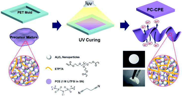 | ||
| Scheme 1 A schematic representation of the UV curing-assisted fabrication process for PC-CPE, wherein chemical structures and photographs depicting mechanical bendability of PC-CPE are also provided. | ||
Characterization of the microstructure, physical properties and electrochemical performance of the plastic crystal composite polymer electrolyte (PC-CPE)
The thermal characteristics of the PC-CPE, particularly focusing on plastic crystal behavior of SN in the PC-CPE, were evaluated by differential scanning calorimetry (DSC, DuPont Q2000) at a heating rate of 20 °C min−1. The UV curing reaction of the PC-CPE was examined using a FT-IR spectrometer (FT-3000, Excalibur) with a spectral resolution of 4 cm−1. The morphology (in particular, dispersion state of Al2O3 nanoparticles) of the PC-CPE was investigated using a field emission scanning electron microscope (FE-SEM, S-4800, Hitachi). The mechanical bendability of the PC-CPE was estimated via a bending test using a universal tensile tester (LR 10K, Lloyd), where samples were subjected to repeated bending cycle (under longitudinal strain ranging from 10 to 30 mm) at a strain rate of 10 mm min−1, where the number of bending cycles before breakdown of the samples represents their bendability.19,23,24 In addition, the mechanical deformability of the PC-CPE was further characterized after being wound around cylindrical glass rods (diameter = 2.5 and 5.0 mm). The maze-patterned PC-CPE was characterized with an optical microscope (BX41, Olympus), in addition to FE-SEM measurement. The viscosity of the PC-CPE precursor mixture was measured with a viscometer (Haake MARS 3, Thermo Electron GmbH). A conventional carbonate-based liquid electrolyte (here, 1 M LiPF6 in ethylene carbonate (EC)/dimethyl carbonate (DMC) = 1/1 v/v) was chosen as a control sample of the PC-CPE. The electrochemical stability window of the PC-CPE was measured by linear sweep voltammetry (LSV) performed on a working electrode of stainless-steel and a counter and reference electrode of lithium metal at a scan rate of 1.0 mV s−1. The ionic conductivity of the PC-CPE was obtained using an impedance analyzer (VSP classic, Bio-Logic) over a frequency range of 1 to 106 Hz under a temperature range of 30 to 70 °C. To evaluate cell performance, a unit cell (2032 coin) was assembled by sandwiching the self-standing PC-CPE between the PCE-soaked LiCoO2 cathode (LiCoO2 (average particle size (D50) = 10 μm)/PVdF binder/Super-P = 95/3/2 w/w/w) and the PCE-soaked Li4Ti5O12 anode (Li4Ti5O12 (average particle size (D50) = 10 μm)/PVdF binder/Super-P = 88/10/2 w/w/w). A control cell was fabricated by assembling the same LiCoO2 cathode and Li4Ti5O12 anode with a polyethylene (PE) separator (thickness = 20 μm, Tonen), followed by being filled with the carbonate-based liquid electrolyte (1 M LiPF6 in EC/DMC = 1/1 v/v). The cells were cycled at a constant charge/discharge current density of 0.2 C (=0.40 mA cm−2)/0.2 C under a voltage range of 1.5–2.7 V. The AC impedance of the cells was measured using the impedance analyzer over a frequency range from 10−3 to 106 Hz. To explore high-temperature stability of cells incorporating PC-CPE, aluminum (Al) pouch-type cells (width × length × thickness = 55 × 70 × 0.8 mm/mm/mm) were fabricated and subjected to a thermal shock test. After exposure to the thermal shock condition (=130 °C/0.5 h), the charge/discharge behavior of cells was monitored at room temperature.Results and discussion
Structural/electrochemical uniqueness of plastic crystal composite polymer electrolytes (PC-CPEs)
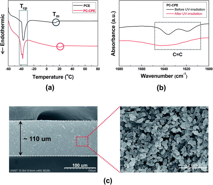
The structural/electrochemical properties of PC-CPEs were characterized, with a focus on its plastic crystal behavior, chemical structure of the UV-cured ETPTA macromer and dispersion state of Al2O3 nanoparticles.The DSC thermograms (Fig. 1a) show that two endothermic peaks assigned to characteristic transition temperatures of SN (TCP (from crystalline to plastic phase) ∼ −39 °C and Tm (from plastic crystalline phase to melted state) ∼13 °C)20–22 are observed in the PC-CPE. Comparison with the thermogram of PCE itself reveals no appreciable difference in the phase transition behavior, which indicates that the introduction of the UV-cured ETPTA/Al2O3 framework does not disrupt the thermal characteristics of PCE. More details about plastic crystal behavior of PCE upon addition of lithium salts and variation of the polymer matrix were described in previous publications.20–24
Another key component of the PC-CPE is the UV-cured ETPTA macromer. Fig. 1b exhibits that the characteristic FT-IR peaks assigned to acrylic C![[double bond, length as m-dash]](https://www.rsc.org/images/entities/char_e001.gif) C bonds18,19 of the ETPTA monomer disappeared after exposure to UV irradiation. This result demonstrates that the ETPTA monomer is photo-polymerized under the presence of PCE and Al2O3 nanoparticles. In addition to this FT-IR result, the gel content (i.e., insoluble polymer fraction after solvent (DMC followed by acetone) extraction) of the PC-CPE was measured. Above 99% of gel by weight (here, Al2O3 nanoparticles are excluded)23,24 was observed, which is another evidence to confirm the successful UV curing reaction of the ETPTA monomer.
C bonds18,19 of the ETPTA monomer disappeared after exposure to UV irradiation. This result demonstrates that the ETPTA monomer is photo-polymerized under the presence of PCE and Al2O3 nanoparticles. In addition to this FT-IR result, the gel content (i.e., insoluble polymer fraction after solvent (DMC followed by acetone) extraction) of the PC-CPE was measured. Above 99% of gel by weight (here, Al2O3 nanoparticles are excluded)23,24 was observed, which is another evidence to confirm the successful UV curing reaction of the ETPTA monomer.
A cross-sectional FE-SEM image of the PC-CPE (Fig. 1c) shows that the Al2O3 nanoparticles are densely packed without serious agglomeration in the through-thickness direction. It is noteworthy that the highly reticulated nanoscale interstitial voids formed between the Al2O3 nanoparticles, corresponding to the space originally occupied with PCE that was removed using DMC (as an etching solvent) prior to the SEM measurement, represent the formation of well-networked ion-conductive pathways in the PC-CPE. The larger content of Al2O3 nanoparticles (Al2O3/(PCE + ETPTA) = 66/34 w/w) and their good compatibility with other components are expected to enable the development of such a unique porous morphology (i.e., highly-interconnected PCE phase in combination with the UV-cured ETPTA/Al2O3 framework). The PCE-based, well-developed ion conductive channels in the PC-CPE are expected to play a crucial role in providing satisfactory level of cell performance, which will be further discussed in the following section.
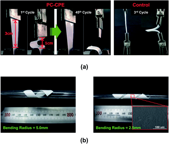
The mechanical flexibility of the PC-CPE was quantitatively examined using a bending test (Fig. 2a). The PC-CPE shows strong resistance to mechanical rupture upon repeated bending cycle (under longitudinal strain ranging from 1 to 3 cm). Comparison with the result of a control sample incorporating no Al2O3 nanoparticles verifies that the UV-cured ETPTA/Al2O3 framework effectively contributes to the mechanical bendability of the PC-CPE. While the control sample is broken down just after the 3rd bending cycle, the dimensional stability of the PC-CPE is preserved until the 45th bending cycle. This superior flexibility of the PC-CPE is ascribed to the presence of close-packed Al2O3 nanoparticles, which could serve as a mechanical buffer to mitigate stress localization occurring during the repeated bending cycle. It has already been reported that the advantageous effect of well-dispersed nanoparticles on the mechanical toughness of nanocomposites is mainly due to the creation of micro-voids that dissipate external stress.26,27 To further underline the excellent mechanical flexibility, the PC-CPE was wound around a glass rod. Fig. 2b shows that no mechanical fracture is observed at the PC-CPE even after being wound around a narrow-diameter rod (=2.5 and 5.0 mm). Moreover, neither micro-scale cracks nor physical defects were found in the PC-CPE (inset of Fig. 2b).
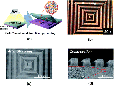
Another noteworthy achievement of the PC-CPE is the provision of a wide range of form factors. The PC-CPE precursor mixture (i.e., prior to UV irradiation) exhibits unique rheological characteristics, in comparison to a conventional carbonate-based liquid electrolyte (here, 1 M LiPF6 in EC/DMC = 1/1 v/v) showing low viscosity and Newtonian fluid behavior (Fig. S1, ESI†). Specifically, the viscosity of the PC-CPE precursor mixture is substantially high and also decreases with increasing shear rate, representing a kind of shear-thinning behavior. Details on the rheological behavior of the electrolyte precursor mixture and its influence on the imprinting process were reported in the previous study.18 A schematic illustration (Fig. 3a) depicts the UV-IL technique-driven micropatterning procedure exploited herein, where pressing maze-patterned PDMS stamp onto the cast slurry of the PC-CPE precursor mixture and subsequent UV irradiation through the transparent PDMS stamp yield self-standing PC-CPE with replica of the maze-pattern. Fig. 3b shows an OM image of the PC-CPE precursor mixture before UV exposure, verifying the formation of the imprinted morphology with an inversely replicated maze pattern. Morphological characterization based on FE-SEM images (Fig. 3c and d) exhibits that the maze-patterned PC-CPE with finely-defined vertical edges is successfully formed, underlying the fabrication of the solid-state electrolyte with tunable dimensions down to micrometer scale. A high-magnification view (inset of Fig. 3d) demonstrates that Al2O3 nanoparticles are closely packed in the micropatterned PC-CPE.
Electrochemical performance of cells assembled with plastic crystal composite polymer electrolytes
The electrochemical performance of cells incorporating PC-CPE was characterized. It should be noted that the cell assembled with the PC-CPE does not incorporate a polyolefin separator membrane, implying that the PC-CPE acts as an electrolyte and also a separator membrane that keeps electrical isolation between electrodes.The temperature-dependent ionic conductivity of the PC-CPE was measured and compared with that of the carbonate-based liquid electrolyte (1 M LiPF6 in EC/DMC = 1/1 v/v) (Fig. 4). Although the ionic conductivity of the PC-CPE was found to be slightly lower than that of the carbonate-based liquid electrolyte, the PC-CPE delivers a satisfactory level of ionic conductivity (for example, 1.02 × 10⁻³ S cm−1 at room temperature), which is attributed to the well-interconnected ion-conductive channels in the PC-CPE (shown in Fig. 1c). Meanwhile, the electrochemical stability window of PC-CPE was estimated from LSV curves (Fig. S2, ESI†). No electrochemical decomposition of any component in the PC-CPE takes place below 5.0 V vs. Li+/Li, indicating potential application to high-voltage batteries. In addition, owing to the UV-cured ETPTA/Al2O3 framework, the PC-CPE shows the slight improvement in the anodic stability compared to the PCE. Further analysis of the electrochemical stability of the PC-CPE will be conducted in future studies.
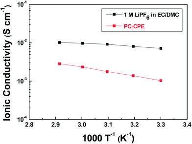 | ||
| Fig. 4 Temperature-dependent ionic conductivity (temperature range = 30– 70 °C) of PC-CPE and carbonate-based liquid electrolyte (1 M LiPF6 in EC/DMC = 1/1 v/v). | ||
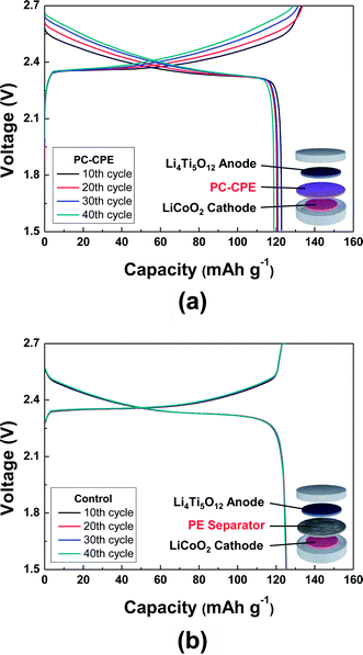
Fig. 5 shows charge/discharge profiles of cells as a function of cycle number at a constant charge/discharge current density (=0.2 C/0.2 C) under a voltage range of 1.5–2.7 V. Here, a cell incorporating the carbonate-based liquid electrolyte (1 M LiPF6 in EC/DMC = 1/1 v/v) and a PE separator was compared as a control system. The cell assembled with the PC-CPE presents an initial discharge capacity of 123 mA h g−1 and also stable charge/discharge behavior up to the 40th cycle, although the capacity retention (=96.9%) appears to be slightly lower than that (=99.6%) of the control cell. This good cycling performance of the PC-CPE was verified by analyzing the AC impedance spectra of cells after the 1st and the 40th cycle (Fig. S3, ESI†). The increase in cell impedance during the cycling is found to be negligibly small (ZRe (40th cycle) − ZRe (1st cycle) = ΔZRe < 10 ohm).
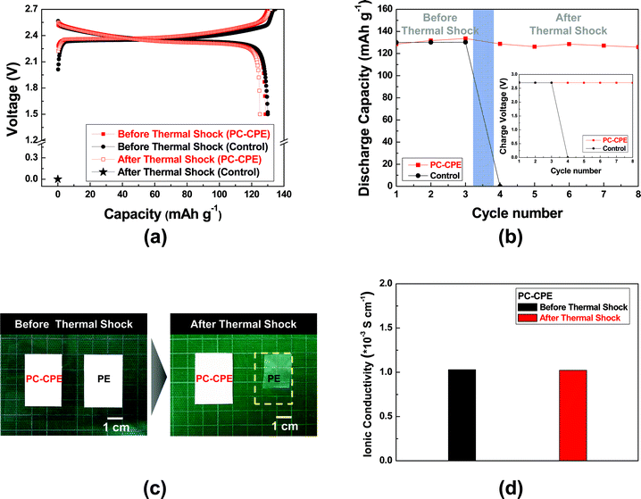
To elucidate the effect of PC-CPE on the thermal stability of a cell, Al pouch-type cells were fabricated. The cells were subjected to the thermal shock condition (=130 °C/0.5 h) and then their cell performance was monitored at room temperature. Fig. 6a shows that the control cell assembled with the carbonate-based electrolyte and the PE separator loses its electrochemical activity after exposure to the thermal shock. Specifically, the cell voltage is down to 0 V and does not return to an initial charge state, indicating the occurrence of internal-short circuit between the anode and the cathode. This internal-short circuit failure may result from thermal shrinkage of the PE separator and also the presence of a volatile carbonate-based electrolyte. In contrast, the cell incorporating the PC-CPE shows stable charge/discharge profiles after the thermal shock. This superior thermal stability of the PC-CPE was further confirmed by observing the inappreciable growth in cell impedance (Fig. S4, ESI†). Fig. 6b summarizes the variation in discharge capacity and charge voltage (inset of Fig. 6b) of the cells before/after the thermal shock.
To attain in-depth understanding of the influence of separators on internal short-circuit failure of cells, dimensional change of the PC-CPE and the PE separator was examined after exposure to the same thermal shock condition (Fig. 6c). The area-based dimensional shrinkage (ΔA) of the PC-CPE was found to be negligibly small, as compared to the PE separator (ΔA ∼ 43%). This result demonstrates that the PC-CPE could act as a self-standing solid-state electrolyte outperforming the PE separator membrane in terms of thermal shrinkage. Commercial PE separators are known to suffer from large thermal shrinkage upon exposure to high-temperature, because of their low melting temperature (below 140 °C) and stretching process essentially used for separator manufacturing.28,29 This poor thermal stability of PE separators is considered as a major cause of the internal short-circuit failures. Meanwhile, the ionic conductivity of the PC-CPE was compared before/after the same thermal shock (Fig. 6d). No decrease in the ionic conductivity was observed, demonstrating the excellent thermal tolerance of the PC-CPE.
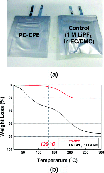
As another piece of evidence to prove the superior thermal stability of the PC-CPE, the change in cell dimension after the thermal shock test was examined. Fig. 7a shows that the cell incorporating the PC-CPE remains intact without dimensional distortion, in comparison to the control cell that was greatly swollen up. The dynamic mode TGA measurement (Fig. 7b) of the PC-CPE and carbonate-based electrolyte delivers meaningful data to explain this intriguing behavior of cell swelling. Negligible loss in weight was observed at the PC-CPE up to approximately 130 °C, verifying the excellent thermal stability of the PC-CPE. On the other hand, the carbonate-based electrolyte shows the rapid weight loss mainly due to the presence of volatile DMC component (boiling temperature ∼ 90 °C).15,16
Conclusion
We have presented the PC-CPE as a new class of shape-deformable and thermally stable solid-state electrolyte for flexible/safer lithium-ion batteries. The in-depth structural characterization exhibited that the PCE was successfully combined with the UV-cured ETPTA macromer/close-packed Al2O3 nanoparticle framework, leading to the PC-CPE. In comparison to the conventional carbonate-based liquid electrolyte, the PC-CPE provided the remarkable improvement in mechanical properties and thermal stability. The PC-CPE precursor mixture with well-tailored rheological characteristics, in collaboration with the UV-IL process, allowed the development of the PC-CPE featuring microscale maze-pattern. Even after exposure to the thermal shock (=130 °C/0.5 h), the cell incorporating the PC-CPE delivered the stable charge/discharge behavior without suffering from safety problems such as cell swelling and internal short-circuit failure. We believe that the material/structure concept used for fabrication of PC-CPE is simple and versatile, which thus can be readily applicable to a wide variety of next-generation flexible energy storage systems as a platform strategy enabling advanced solid-state electrolytes.Acknowledgements
This work was supported by the Energy Efficiency and Resources R&D program (20112010100150) under the Ministry of Knowledge Economy, Republic of Korea, Research Fund of the UNIST (Ulsan National Institute of Science and Technology) in 2012, a grant from the R&D Program (Industrial Strategic Technology Development) funded by the Ministry of Knowledge Economy (MKE), Republic of Korea, and the BK21 Plus funded by the Ministry of Education, Korea (10Z20130011057).References
- M. Armand and J. M. Tarascon, Nature, 2008, 451, 652–657 CrossRef CAS PubMed.
- K. Jost, C. R. Perez, J. K. McDonough, V. Presser, M. Heon, G. Dion and Y. Gogotsi, Energy Environ. Sci., 2011, 4, 5060–5067 CAS.
- S. Y. Lee, K. H. Choi, W. S. Choi, Y. H. Kwon, H. R. Jung, H. C. Shin and J. Y. Kim, Energy Environ. Sci., 2013, 6, 2414–2423 CAS.
- G. Zhou, F. Li and H. M. Cheng, Energy Environ. Sci., 2014, 7, 1307–1338 CAS.
- Y. H. Lee, J. S. Kim, J. Noh, I. Lee, H. J. Kim, S. Choi, J. Seo, S. Jeon, T. S. Kim, J. Y. Lee and J. W. Choi, Nano Lett., 2013, 13, 5753–5761 CrossRef CAS PubMed.
- M. R. Palacin, Chem. Soc. Rev., 2009, 38, 2565–2575 RSC.
- G. Jeong, Y. U. Kim, H. Kim, Y. J. Kim and H. J. Sohn, Energy Environ. Sci., 2011, 4, 1986–2002 CAS.
- K. T. Nam, D. W. Kim, P. J. Yoo, C. Y. Chiang, N. Meethong, P. T. Hammond, Y. M. Chiang and A. M. Belcher, Science, 2006, 312, 885–888 CrossRef CAS PubMed.
- N. Li, G. Zhou, F. Li, L. Wen and H. M. Cheng, Adv. Funct. Mater., 2013, 23, 5429–5435 CrossRef CAS PubMed.
- X. Jia, Z. Chen, X. Cui, Y. Peng, X. Wang, G. Wang, F. Wei and Y. Lu, ACS Nano, 2012, 6, 9911–9919 CrossRef CAS PubMed.
- A. Vlad, A. L. M. Reddy, A. Ajayan, N. Singh, J. Gohy, S. Melinte and P. M. Ajayan, Proc. Natl. Acad. Sci. U. S. A., 2012, 109, 15168–15173 CrossRef CAS PubMed.
- N. Li, Z. Chen, W. Ren, F. Li and H. M. Cheng, Proc. Natl. Acad. Sci. U. S. A., 2012, 109, 17360–17365 CrossRef CAS PubMed.
- H. Gwon, H. S. Kim, K. U. Lee, D. H. Seo, Y. C. Park, Y. S. Lee, B. T. Ahn and K. Kang, Energy Environ. Sci., 2011, 4, 1277–1283 CAS.
- L. Hu and Y. Cui, Energy Environ. Sci., 2012, 5, 6423–6435 Search PubMed.
- K. Xu, Chem. Rev., 2004, 104, 4303–4417 CrossRef CAS.
- E. Quartarone and P. Mustarelli, Chem. Soc. Rev., 2011, 40, 2525–2540 RSC.
- J. Hassoun, S. Panero, P. Reale and B. Scrosati, Adv. Mater., 2009, 21, 4807–4810 CrossRef CAS PubMed.
- E. H. Kil, K. H. Choi, H. J. Ha, S. Xu, J. A. Rogers, M. R. Kim, Y. G. Lee, K. M. Kim, K. Y. Cho and S. Y. Lee, Adv. Mater., 2013, 25, 1395–1400 CrossRef CAS PubMed.
- S. H. Kim, K. H. Choi, S. J. Cho, E. H. Kil and S. Y. Lee, J. Mater. Chem. A, 2013, 1, 4949–4955 CAS.
- P. J. Alarco, Y. Abu-Lebdeh, A. Abouimrane and M. Armand, Nat. Mater., 2004, 3, 476–481 CrossRef CAS PubMed.
- S. Das, S. J. Prathapa, P. V. Menezes, T. N. Row and A. J. Bhattacharyya, J. Phys. Chem. B, 2009, 113, 5025–5031 CrossRef CAS PubMed.
- L. Z. Fan, Y. S. Hu, A. J. Bhattacharyya and J. Maier, Adv. Funct. Mater., 2007, 17, 2800–2807 CrossRef CAS PubMed.
- H. J. Ha, E. H. Kil, Y. H. Kwon, J. Y. Kim, C. K. Lee and S. Y. Lee, Energy Environ. Sci., 2012, 5, 6491–6499 CAS.
- K. H. Choi, S. J. Cho, S. H. Kim, Y. H. Kwon, J. Y. Kim and S. Y. Lee, Adv. Funct. Mater., 2014, 24, 44–52 CrossRef CAS PubMed.
- J. Yao, A. P. Le, M. V. Schulmerich, J. Maria, T. W. Lee, S. K. Gray, R. Bhargava, J. A. Rogers and R. G. Nuzzo, ACS Nano, 2011, 5, 5763–5774 CrossRef CAS PubMed.
- H. E. H. Meijer and L. E. Govaert, Prog. Polym. Sci., 2005, 30, 915–938 CrossRef CAS PubMed.
- B. Cotterell, J. Y. H. Chia and K. Hbaieb, Eng. Fract. Mech., 2007, 74, 1054–1078 CrossRef PubMed.
- P. Arora and Z. Zhang, Chem. Rev., 2004, 104, 4419–4462 CrossRef CAS.
- E. S. Choi and S. Y. Lee, J. Mater. Chem., 2011, 21, 14747–14754 RSC.
Footnote |
| † Electronic supplementary information (ESI) available. See DOI: 10.1039/c4ta00494a |
| This journal is © The Royal Society of Chemistry 2014 |

