
 Open Access Article
 This Open Access Article is licensed under a
 Creative Commons Attribution 3.0 Unported Licence
Experimental and molecular dynamics characterization of dense microemulsion systems: morphology, conductivity and SAXS†
E.
Negro
a,
R.
Latsuzbaia
a,
A. H.
de Vries
b and
G. J. M.
Koper
*a
aDepartment of Chemical Engineering, Delft University of Technology, Julianalaan 136, 2628 BL Delft, Netherlands. E-mail: g.j.m.koper@tudelft.nl
bMolecular Dynamics Group, Groningen Biomolecular Sciences and Biotechnology Institute and Zernike Institute for Advanced Materials, University of Groningen, Nijenborgh 7, 9747 AG Groningen, Netherlands
First published on 12th September 2014
Abstract
Microemulsions are exciting systems that are promising as tuneable self-assembling templating reaction vessels at the nanoscale. Determination of the nano-structure of microemulsions is, however, not trivial, and there are fundamental questions regarding their design. We were able to reproduce experimental data for an important microemulsion system, sodium-AOT–n-heptane–water, using coarse-grained simulations involving relatively limited computational costs. The simulation allows visualization and deeper investigation of controversial phenomena such as bicontinuity and ion mobility. Simulations were performed using the Martini coarse-grained force field. AOT bonded parameters were fine-tuned by matching the geometry obtained from atomistic simulations. We investigated several compositions with a constant ratio of surfactant to oil while the water content was varied from 10 to 60% in weight. From mean square displacement calculation of all species, it was possible to quantify caging effects and ion mobility. Average diffusion coefficients were calculated for all charged species and trends in the diffusion coefficients were used to rationalize experimental conductivity data. Especially, the diffusion coefficient of charged species qualitatively matched the variation in conductivity as a function of water content. The scattering function was calculated for the hydrophilic species and up to 40% water content quantitatively matched the experimental data obtained from small angle X-ray scattering measurements. For higher water contents, discrepancies were observed and attributed to a nearby phase separation. In particular, bicontinuity of water and oil was computationally visualized by plotting the coordinates of hydrophilic beads. Equilibrated coarse-grained simulations were reversed to atomistic models in order both to compare ion mobility and to catch finer simulation details. Especially, it was possible to capture the intimate ion pair interaction between the sodium ion and the surfactant head group.
Introduction
Bicontinuous microemulsions (BMEs) are a special class of thermodynamically stable, single phase emulsions, type IV in the Winsor classification,1 where surfactant is mixed with almost equal amounts of oil and water in such a way that both water and oil form continuous channels. Such a structure is stabilized by a large amount of surfactant (∼50% in weight with respect to the final mixture). The concept of BMEs was introduced in 19762 and since then, these colloidal structures have been extensively studied using various techniques. However, their potential for application has been largely overlooked in comparison to that of reverse micelles (RMs).BMEs recently resulted in an optimal template for synthesis of metallic nanoparticles3–6 and Metal Organic Framework (MOF) nanocrystals,7 for enzymatic catalysis,8 and for assembly of mesoporous nanocomposites.9 Additionally, they recently attract again great interest for surfactant “Enhanced Oil Recovery” applications having oil scarcity as the main driving force.10 BMEs provide a sponge-like mesoporous nanostructure with a large interfacial area between polar and apolar domains. They allow the confinement of species in the water phase as do RMs but they have the advantage that the template motion is itself constrained. For example, these structures are believed to be crucial for the synthesis of stable nanoparticles since they allow the metal precursor ions to diffuse freely but they do not allow the diffusion of nanoparticles.5 In that way, the reaction timescale is much faster than the growth timescale, resulting in the formation of monodisperse nanoparticles. Additionally, higher yields can be achieved because of the higher water content (up to 40% in weight) compared to conventional RM synthesis.4,5 Understanding how ME structure depends on composition is crucial for providing a molecular basis for interpreting experimental results and investigating the effects on for example nanoparticles synthetized in them.
Molecular Dynamics (MD) simulations have been widely used to investigate microemulsion systems, especially concerning RM size, shape and shape transitions,11–13 water behaviour as a function of the distance from the interface14–19 and head-group–solute interactions.18,20,21 However, simulations of ternary systems were limited to low surfactant concentrations and deal mainly with RM systems. One of the reasons is that most of the simulations were atomistic, or all atoms (AA), whose computational costs are in general too high to capture timescales and length scales necessary to characterize microemulsion systems containing large amount of surfactant, in which diffusion is slowed down by higher viscosity of the system and characteristic dimensions are on the order of tens of nanometers.22
Coarse-grained (CG) simulations allow significant computational cost reduction compared to AA simulations and are suitable to simulate systems requiring microseconds and micrometres. Hybrid systems, using AA for interfacial regions and CG for the rest, have also been adopted to reduce computational costs.22,23 The Martini CG force-field (FF), a fast, easy and efficient simulation tool, was developed in 2003 by Marrink et al.24 for biomolecular applications, becoming in less than a decade one of the most widely used CG force field for a broad range of applications. In particular it appears well suited to study formation of micelles, allowing simulation times long enough to equilibrate this kind of systems.13,25–27
In this work, we aim to investigate dense microemulsion systems formed with dioctyl sodium sulfosuccinate or docusate sodium, known as Na-AOT, because of its widespread use in many applications and long standing investigation in our group as template for metal nanoparticles synthesis. This molecule has been widely investigated by AA MD simulations12,16,18,19,28 and more recently by a few CG models.10,29
The goal of this work is to provide a Martini CG model for the system water–Na-AOT–n-heptane, to map out an important part of the ternary phase diagram and to compare the resulting structures/morphologies to geometrical models available in the literature30 and to experimental characterizations such as conductivity and small angle X-ray scattering (SAXS) data. First, Na-AOT and n-heptane bonded interaction parameters are fine tuned in Martini according to AA MD simulations and part of the phase diagram is mapped out and compared to a theoretical model. Bicontinuity is computationally visualized. Secondly, diffusion coefficients of charged species are compared to experimental conductivity data. Mean square displacements (MSDs) of charged species are used to investigate caging effects. Thirdly, scattering functions calculated from radial distribution functions of hydrophilic species are compared to SAXS data. Finally, after back mapping equilibrium structures to the AA model of three CG simulations, further AA MD simulations are performed to evaluate effects due to CG loss of detail compared to AA.
Methods
Phase diagram calculation – the geometrical model
A phase diagram of the ternary system employed in this study was calculated using a simplistic geometrical model developed by Andre et al.,30 that predicts structural transitions and supra-aggregation processes which are imposed by geometrical constraints. The model is solely based on a geometry of surfactant and related curvature of the oil–water interface and therefore requires calculations of the: (i) composition of the system, here expressed as the water weight fraction,![[w with combining macron]](https://www.rsc.org/images/entities/i_char_0077_0304.gif) ; (ii) surfactant parameter, s, which is given by the ratio v/(lsa0) where v is the molecular volume of the surfactant, ls is the effective chain length of the surfactant tail, and a0 is the optimal head group surface area;31,32 and (iii) packing parameter, which is the ratio between the volume actually occupied by the cylinders/spheres and that of the unit cells.30 During all calculations it is assumed that all the surfactant is located in the oil–water interface.30 Based on the geometrical model, radii of spherical, Rw_s, and cylindrical, Rw_c, aggregates can be deduced according to eqn (1) and (2), respectively:
; (ii) surfactant parameter, s, which is given by the ratio v/(lsa0) where v is the molecular volume of the surfactant, ls is the effective chain length of the surfactant tail, and a0 is the optimal head group surface area;31,32 and (iii) packing parameter, which is the ratio between the volume actually occupied by the cylinders/spheres and that of the unit cells.30 During all calculations it is assumed that all the surfactant is located in the oil–water interface.30 Based on the geometrical model, radii of spherical, Rw_s, and cylindrical, Rw_c, aggregates can be deduced according to eqn (1) and (2), respectively:| Rw_s = 3sls | (1) |
| Rw_c = 2sls | (2) |
Materials and experimental methods
The surfactant, sodium bis(2-ethylhexyl)sulphosuccinate, also known as Na-AOT (C20H37NaO7S, 99%), and the oil, n-heptane (99.9%), were purchased from Sigma-Aldrich BV and used as received. Water produced by Milli-Q Ultra-Pure-Water purification system of Millipore BV was used in all sample formulations. All preparations and analysis were carried out at room temperature and atmospheric pressure. Surfactant and oil were mixed in the ratio 2![[thin space (1/6-em)]](https://www.rsc.org/images/entities/char_2009.gif) :1 in weight and sonicated for one hour to speed up dissolution of the surfactant. Subsequently, water was added to the mixture of oil and surfactant in different ratio in weight. After circa 1 hour, the microemulsions were found to be clear and were considered homogeneous and ready for further experiment or analysis. Conductivity measurements were carried out using a conductivity meter model 712 from Metrohm AG. Small angle X-ray scattering (SAXS) was conducted using an AXS D8 Discover instrument from Bruker AG. Microemulsion samples where filled in a 1 mm thick quartz capillary set at a distance of 30 cm from the detector. The X-ray source was a tube operated at 40 kV and 40 mA and produced predominantly copper Kα radiation of wavelength 0.154 nm. The scattering data from the experiments were radially integrated obtaining the intensity as a function of d-spacing obtained by applying Bragg's law. Dynamic light scattering (DLS) measurements were performed on the Zetasizer Nano ZS from Malvern Instruments Limited using the 173° angle non-invasive back-scatter mode and the M3-phase analysis light scattering mode, respectively. The instrument had a red 4.0 mW 633 nm He–Ne laser. The multiple peak high-resolution fitting procedure was used to obtain the particle size distribution from the auto-correlation function.
:1 in weight and sonicated for one hour to speed up dissolution of the surfactant. Subsequently, water was added to the mixture of oil and surfactant in different ratio in weight. After circa 1 hour, the microemulsions were found to be clear and were considered homogeneous and ready for further experiment or analysis. Conductivity measurements were carried out using a conductivity meter model 712 from Metrohm AG. Small angle X-ray scattering (SAXS) was conducted using an AXS D8 Discover instrument from Bruker AG. Microemulsion samples where filled in a 1 mm thick quartz capillary set at a distance of 30 cm from the detector. The X-ray source was a tube operated at 40 kV and 40 mA and produced predominantly copper Kα radiation of wavelength 0.154 nm. The scattering data from the experiments were radially integrated obtaining the intensity as a function of d-spacing obtained by applying Bragg's law. Dynamic light scattering (DLS) measurements were performed on the Zetasizer Nano ZS from Malvern Instruments Limited using the 173° angle non-invasive back-scatter mode and the M3-phase analysis light scattering mode, respectively. The instrument had a red 4.0 mW 633 nm He–Ne laser. The multiple peak high-resolution fitting procedure was used to obtain the particle size distribution from the auto-correlation function.
Computational methods
All simulations were performed with the GROMACS simulation package version 4 (ref. 33) using periodic boundary conditions in all directions. | ||
| Fig. 1 The coarse-grained model for Na-AOT surfactant and n-heptane. Circles include the atoms that are grouped into beads and are coloured to indicate their nature: red-Q, blue-N, green-C. The numbers reflect the order in which the model is represented in the topology. | ||
CG systems were prepared by first randomly placing 100 AOT molecules in a cubic simulation box of dimensions xyz nm; values are specified for each simulation in Table 2 and S1–S3.† Next, 222 n-heptane molecules were added randomly to the same volume, and finally, the volume was filled with randomly placed ion and water beads. Each system was energy minimized using the steepest descent method for 500 steps. These systems were then replicated once in each dimension, creating a simulation volume 8 times larger than the initial set-up. After a short MD relaxation run, simulations of 1 μs were performed, allowing the system to self-assemble and equilibrate. Analysis of morphology, diffusion, and structural characterization was performed on the final 500 ns of the simulation. All simulation times reported here are unscaled (see also discussion of diffusion results). The initial velocities were randomly assigned from a Maxwell distribution at the reference temperature. The equations of motion were integrated numerically using a 20 fs time step. Water, surfactant molecules, ions and oil were separately coupled to a Berendsen thermostat at 298 K with a common coupling time of 1 ps.34 For CG simulations containing 10, 15 and 60% water, the pressure was isotropically controlled at 1 bar using a Berendsen barostat with a coupling time of 3 ps with an isothermal compressibility of 3 × 10⁻⁵ bar−1. For simulations containing 10, 25, 30, 35, 40, 45, 50 and 55% water, the pressure was anisotropically controlled at 1 bar using a Berendsen barostat with a coupling time of 3 ps and with an isothermal compressibility of 3 × 10⁻⁵ bar−1 in x, y, z directions and off-diagonal compressibility set to 0 in order to keep the box rectangular.
Analysis
| MSDk(t) = 〈(kτ+t − kτ)2〉τ,N | (3) |
The total MSD is the sum of the contributions in different directions according to eqn (4):
| MSD(t) = MSDx(t) + MSDy(t) + MSDz(t) | (4) |
From the total MSD, an average diffusion coefficient is calculated from the Einstein relation, eqn (5):
 | (5) |
The combined plots showing the single MSD curves in direction x,y,z provide a rapid insight into the connectedness of the component of interest, discriminating caging effects and free diffusion. Most of these plots are shown in ESI.†
 | (6) |
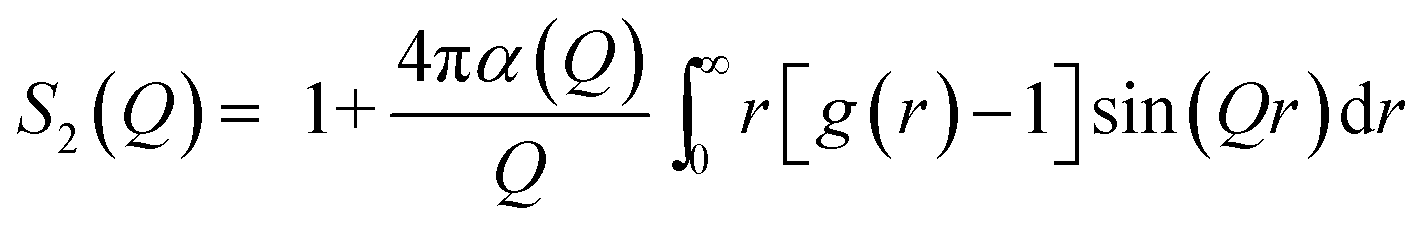
Neglecting inelastic scattering, the scattered intensity, I, is proportional to the differential cross section, a measure of the fraction of incident particles that emerge in various directions, that is proportional to the sum of two factors according to eqn (7):
 | (7) |
 | (8) |
The built-in GROMACS tools are capable to calculate a scattering function h(q) that is very similar to S2, according to eqn (9):
 | (9) |
h(q) was calculated using two approaches: simplified and exact. For the simplified approach, RDF was calculated for hydrophilic species (H) only, being water, Na+ and head-group beads, according to eqn (10):
 | (10) |
For the exact approach, all contributions have been taken into account. In general, for a material consisting of different types of atoms, g(r) can be decomposed into a linear combination of M(M + 1)/2 partial correlation functions, gJK(r) according to eqn (11)
 | (11) |
| γJK ∝ (2 − δJK)cJcK〈bJ〉〈bk〉 | (12) |
 | (13) |
Results and discussion
Phase diagram investigation
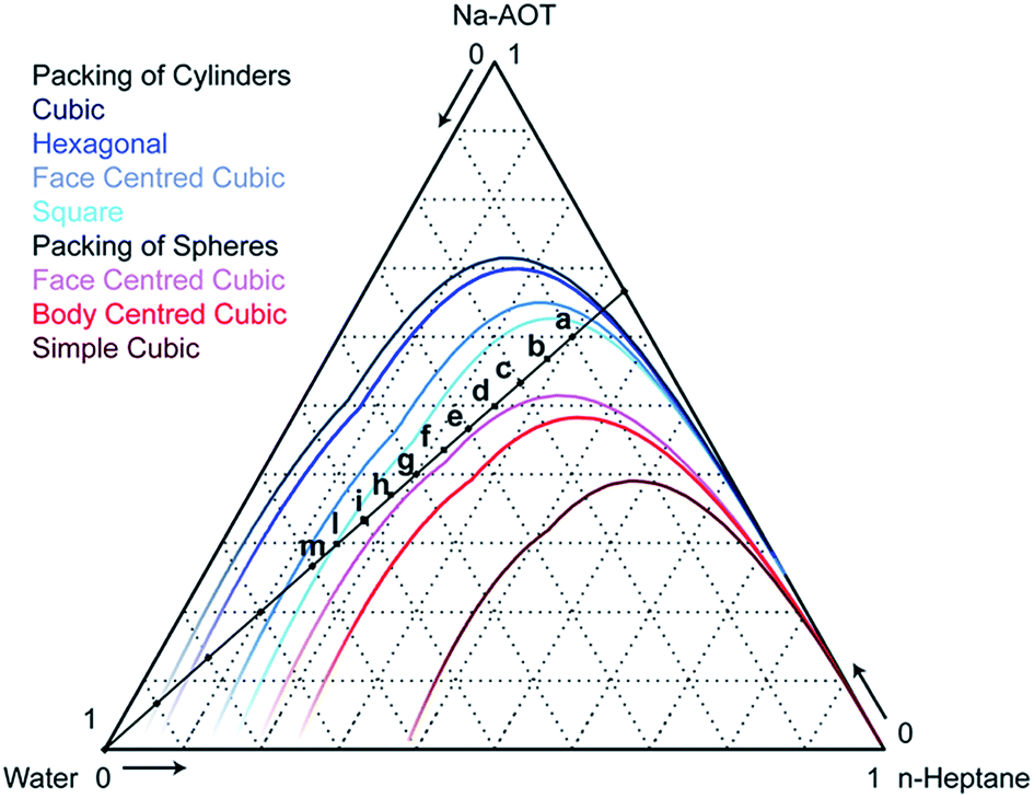 | ||
| Fig. 2 Phase diagram of water–Na-AOT–n-heptane systems calculated according to the geometrical model of Andre.29 The coloured lines are the upper boundaries of the region in which the indicated morphology is geometrically allowed. Compositions are expressed in weight fractions. The compositions a through m are studied experimentally and by modelling. | ||
Refining bonded parameters. The AOT molecule can be coarse-grained using a Martini model 4-to-1 mapping scheme as shown in Fig. 1, where the assignment of the beads is straightforward when comparing the chemical entities sulfonic anion head group, ester linker, and aliphatic tails to those found in the phospholipids for which the model was originally developed.24,48 Our initial model employed standard bonded parameters taken from the lipids that are given in Table 1. Also, heptane was modelled using the standard model for octane, a 2-bead hydrocarbon. The Na+ bead in the Martini model represents a hydrated ion, with 3 or 4 water molecules included in the bead. Here, in calculating the mass ratios of the mixtures, we take the Na+-bead to be associated with three water molecules.
| AOT | ||||
|---|---|---|---|---|
| Bond | Standard CG | Refined CG | ||
| b 0 nm−1 | k b kJ−1 mol−1 nm−2 | b 0 nm−1 | k b kJ−1 mol−1 nm−2 | |
| 1–2 | 0.47 | 1250 | 0.28 | 1250 |
| 2–3 | 0.37 | 1250 | 0.39 | 1250 |
| 2–4 | 0.47 | 1250 | 0.39 | 1250 |
| 4–5 | 0.47 | 1250 | 0.39 | 1250 |
| 3–6 | 0.47 | 1250 | 0.39 | 1250 |
| 6–7 | 0.47 | 1250 | 0.39 | 1250 |
| Angle | φ 0/° | k φ kJ−1 mol−1 nm−2 | φ 0/° | k φ kJ−1 mol−1 nm−2 |
|---|---|---|---|---|
| 1–2–3 | 120 | 25 | 60 | 45 |
| 1–2–4 | 180 | 25 | 120 | 25 |
| 3–2–4 | — | — | 150 | 25 |
| 2–3–6 | — | — | 130 | 45 |
| 2–4–5 | 180 | 25 | 100 | 45 |
| 3–6–7 | 180 | 25 | 100 | 65 |
| HEP | ||||
|---|---|---|---|---|
| Bond | Standard CG | Refined CG | ||
| b 0 nm−1 | k b kJ−1 mol−1 nm−2 | b 0 nm−1 | k b kJ−1 mol−1 nm−2 | |
| 1–2 | 0.47 | 1250 | 0.35 | 1250 |
Using spontaneous aggregation from a starting structure containing 80 weight percent Na-AOT and n-heptane in 2:1 w/w ratio (800 Na-AOT and 1776 n-heptane molecules) and 20 weight percent water, a predominantly lamellar structure formed within 100 ns, as shown in Fig. 3a. Cell size and number of molecules are reported in Table S1,† and further analysis of the structural organization in Fig. S1.† It can be clearly seen from Fig. S1† that hydrophobic beads are continuous in the x and y directions but they are not in the z direction. Based on experimental data and the theoretical hard-sphere model, a lamellar morphology is unlikely, and we sought to refine the CG model to better and more specifically represent the AOT and n-heptane molecules. Note that the 4-to-1 mapping scheme necessarily makes the model somewhat generic in the sense that using two beads for the lipid tail may represent anything between a 6- and 10-carbon aliphatic chain. In fact, given the parameterization to linear alkanes, the standard CG model may be more representative of a straight-chain Na-di(C8:0)phosphatidic acid–octane–water mixture. Short-chain phosphatidic acids are known to form micelles in water,49 and the general effect of adding alkanes to lipids is to promote more inverse curvature assemblies;50 the lamellar structure is consistent with these data.
 | ||
| Fig. 3 Final snapshot for the system containing 20% water for (a) standard CG, 1 μs, (b) AA, 400 ns, (c) refined CG, 1 μs. Water – light blue, n-heptane – yellow, Na+ – blue, AOT head group – purple, AOT tail – orange. The simulated cell has been replicated once in each dimension, creating a simulation volume 8 times larger, in order to allow a better visualization of the structure. | ||
Refinement of the AOT and n-heptane models was based on AA simulations using an in-house version of the GROMOS53A6 FF, parameter files available upon request. The same 20/80 water/surfactant + oil w/w mixture as discussed above, containing 800 Na-AOT molecules, formed a BME spontaneously from a random starting structure using this atomistic model, see Fig. 3b. Bond length and angle distributions were measured for the surfactant and n-heptane molecules after applying the mapping scheme shown in Fig. 1 to the AA trajectory. We changed reference bond lengths and angles in the CG model according to the peaks of the mapped model distributions, and increased selected force constants for the angles to better reflect the width of the distributions. The parameters are given in Table 1. Although bond distributions tended to be narrower in the mapped model than in the Martini model, we chose to keep the standard bond force constants. An example comparing the distributions found in the mapped AA simulations, in the standard model, and in the refined model is shown in Fig. 4. All comparisons of bond angles, bond lengths and dihedral angles distributions are shown in Fig. S2–S4,† respectively, while two examples are shown in Fig. 4. Note that in some cases, the mapped distributions are bimodal, e.g.Fig. 4a; these cannot be reproduced using simple harmonic potentials. The main effect of the refined bonded parameters is a better representation of the shape of the AOT molecule, doing justice to the branching of the aliphatic tails and the position of the charged head group. Since it was our aim to stay close to the original Martini model, no further refinements were made, but it is clear that a closer match could be achieved.
 | ||
| Fig. 4 (a) Bond angle 1–2–3 distribution and (b) bond length 2–4 distribution for CG standard, CG refined and mapped AA. The indices refer to AOT beads depicted in Fig. 1. | ||
Spontaneous assembly simulations using the refined CG model, in which the bonded parameters represent the shape and size of the Na-AOT and n-heptane molecules more specifically, does lead to BME for the 20/80 mixture, see Fig. 3c. Fig. 5 and S5† show that hydrophilic beads form continuous domains in all directions for refined CG and AA simulations, respectively. Thus, at this composition, the AA and CG models are in mutual agreement and consistent with previous interpretations of experimental data and the hard-sphere model.
 | ||
| Fig. 5 Slices of the final frame of system c, containing 20% water, CG refined simulation of planes perpendicular to (a) x axis, (b) y axis, (c) z axis. Only hydrophilic beads are represented, being water, Na+ and AOT head-group. Beads are coloured according to the layer they are in. The layers are 1 nm thick. Distribution profile across Cartesian direction for (d) hydrophilic beads, water, Na+ and AOT head group, (e) hydrophobic beads, AOT apolar tail and n-heptane. | ||
Phase diagram investigation. We next investigated the behaviour of the CG model along the dilution line shown in Fig. 2, varying the water content from 10 to 60 weight percent, keeping the surfactant–oil weight ratio constant at 2
:1, corresponding to systems a–m. Systems were formed using spontaneous aggregation simulations starting from random mixtures of surfactant, oil, and water. The compositions, unit cell dimensions, and morphological classifications of the systems are given in Table 2. Fig. 6 shows the final structures of our simulations for the systems.
| Water% | Box size nm−3 | n w | n s | n o | Continuityc | Structure | |
|---|---|---|---|---|---|---|---|
| a Isotropic pressure coupling. b Anisotropic pressure coupling, and started after adding 5% water to the 55% system (multiplied 8 times and relaxed). c Directions in which water is continuous. | |||||||
| a | 10 | 14 × 8 × 9 | 3296 | 800 | 1776 | XYZ | IW |
| b | 15a | 10 × 10 × 10 | 5216 | 800 | 1776 | XYZ | BME |
| c | 20a | 10 × 10 × 10 | 7424 | 800 | 1776 | XYZ | BME |
| d | 25 | 11 × 9 × 12 | 9888 | 800 | 1776 | Z | HC |
| e | 30 | 11 × 10 × 11 | 12704 |
800 | 1776 | YZ | IW |
| f | 35 | 8 × 10 × 16 | 15968 |
800 | 1776 | X | IM/BCC |
| g | 40 | 10 × 10 × 16 | 19744 |
800 | 1776 | — | FCC |
| h | 45 | 12 × 11 × 12 | 24256 |
800 | 1776 | — | W |
| i | 50 | 12 × 12 × 12 | 29632 |
800 | 1776 | Y | C |
| l | 55 | 14 × 9 × 15 | 36224 |
800 | 1776 | Y | BC |
| m | 60a | 26 × 26 × 26 | 355584 |
6400 | 14208 |
— | BCC |
| m* | 60b | 34 × 15 × 35 | 355584 |
6400 | 14208 |
Y | BC |
 | ||
| Fig. 6 Snapshot at the end of 1 μs simulations for the system water–Na-AOT–n-heptane using the refined CG model. Water – light blue, n-heptane – yellow, Na+ – blue, AOT head group – purple, AOT tail – orange. Compositions corresponding to the points depicted in Fig. 2. Simulation details are reported in Table 2. | ||
The morphology of some structures is clearly recognizable. Fig. 6a–c corresponding to 10, 15 and 20% water content, respectively, show percolating water in a continuous oil phase. According to the phase diagram in Fig. 2, we are below the lines of cylinders that can be packed in all different ways. Due to the large amount of surfactant that can stabilize large water–oil interfaces, the most favourable configuration is the formation of continuous nano-channels of one into the other. Fig. S6, S7† and 5 show that hydrophilic beads form a continuous domain in all directions, and the probability distribution plots show that both hydrophobic and hydrophilic beads are continuous in all directions. In contrast, Fig. 6d (25% water content) shows cylinders packed in a hexagonal manner, Fig. 6f (35%) spherical micelles packed in a BCC configuration, while Fig. 6e (30%) a transition between the two. Fig. 6g (40%) shows spheres arranged in a FCC configuration, Fig. 6h (45%) worms and Fig. 6i (50%) cylinders. In Fig. 6l (55%), the coexistence of cylinders of two different sizes can be observed, while in Fig. 6m (60%) spheres are arranged in a BCC configuration. According to phase diagram of Fig. 2, this composition should correspond to cylinders. Experimentally, we observed that this system was tremendously viscous (more than 10 cP) as discussed in more detail later on when discussing SAXS results. All simulations were started from randomly distributed molecules, to avoid hysteresis phenomena. However, for the system containing 60% water, due to the high viscosity, we carried out an additional simulation, m* in Table 2, starting from the final snapshot of the simulation containing 55% water and adding 5% water. The system was then enlarged 8 times and simulations were run for 1 μs. Fig. 6m* shows that in that case, cylinders of two dimensions are obtained. This is likely to be the more realistic configuration, as described later in the conductivity experiments. Additionally, small simulation systems are incapable to simulate proper phase separation, and 60% water content is at the boundary with phase separation occurring at 65% water content. Continuity investigations for all simulated systems are reported Fig. S6–S16;† their interpretation in terms of the morphology, and corresponding qualification are reported in Table 2.
It must be observed than when using the standard CG model, see Table S2† for simulations details, completely different structures were obtained and no BME was found, Fig. S17.† This is due to a bigger volume of the Na-AOT and n-heptane molecule and thus of the apolar phase, as proven by the bigger box dimensions, Table S2.† Also the AOT surfactant parameter can be slightly different before and after refinement.
To further characterize the relation with the morphology and macroscopic measurements, a number of further analyses have been carried out. Results are presented in the following sections.
Conductivity
| k = Λmc | (14) |
 | ||
| Fig. 7 (a) Conductivity as a function of water content measured experimentally by a conductivity meter (pink), and theoretically calculated assuming Na+ as the only diffusing species contributing (green). (b) Diffusion coefficient for water, Na+, AOT and n-heptane calculated from the average MSD at 250 ns. | ||
For the microemulsion of water content below 10%, the conductivity is very low and does not vary much. At these very low water contents microemulsion structures are formed in which the continuous phase is constituted by oil, the conductivity of which is nearly zero. All the water (“bound water”) is immobilized in the core of the nanosized reverse micelles/worms and participates in hydration of the surfactant head group associating with Na+ ions and the head groups forming relatively rigid structures.51,52 Therefore, in this system charge is transported by charged micelles and not by ions, resulting in a very low conductivity.51 When the water content is higher than required for the surfactant hydration, “free” water is available in the micelles. Upon addition of water, micelles grow in size and conductivity is slightly increased because of the higher mobility of the counter ions due to the charge hopping mechanism from one micelle to another.53 However, the conductivity is still below 10−4 mS cm−1.
With further increase of water content (10–30%) the micelles increase in size, elongate and form cylindrical continuous structures which cause a significant jump in the conductivity due to better mobility of the ions in the continuous water channels compared to one in reverse micelles. When reverse micelles are formed again (35–50%), the conductivity drops again. However, above 50% water content conductivity increases again due to continuous channel formation and above 70% water content significant increase of conductivity is observed due to phase inversion/separation. The increase in microemulsion conductivity observed when the water content is raised above the percolation threshold might result from a progressive aqueous droplet interlinking and clustering process. The results agree with the prediction of the geometrical model.
MSD and diffusion coefficient investigation. We calculated MSDx, MSDy and MSDz for a representative sample of 100 beads for water, Na+, n-heptane and the AOT. Some examples of MSD curves calculated for Na+ beads over 250 ns are reported in Fig. 8; all MSD curves for the other systems are reported in Fig. S18 and S19.† From the analysis of the curves and their behaviour as a function of time, it is possible to gain a deeper insight in the structure and continuity of the microemulsion. For example, Fig. 8a shows the MSD curves for the BME system c containing 20% water. MSD curves are similar in the three directions, implying it is an isotropic system. Additionally, part of the beads have a relatively limited mobility, being probably found in the neighbourhood of the surfactant head groups, as previously reported in systems with low water content.16 Some beads can however freely diffuse, as MSD curves keep growing as a function of time, corresponding to beads translating more than 10 nm, basically all over the domain of the simulation cell, a cube of 10 nm side, Table 2. Fig. 8b instead shows the MSD curves for the system g containing 40% water. The system is isotropic as the curves are similar in the three directions. However, the MSD levels off very quickly. Na+ beads are “caged” in spherical water pockets of a dimension corresponding to roughly 4 nm in inner diameter. Finally, Fig. 8c shows MSD curves for the system i containing 50% water.
 | ||
| Fig. 8 MSD curves for 100 Na+ beads for the system containing (a) 20% (b) 40% (c) 50% water. The water structure is shown on the left. | ||
The curves are different in the three directions. Ions can freely diffuse in the y direction while they are “caged” in x and z directions. This is clearly shown also by the different scales, showing MSD up to 1500 nm2 in the y direction and limited to 40 nm2 in x and z directions. In the x and z directions two populations are visible. This scenario corresponds to the coexistence of cylinders/worms of two different sizes, respectively roughly 4 and 1 nm in inner diameter.
Total MSD curves for all the species are reported in Fig. S20.† From the MSD curves, average diffusion coefficients were calculated according to the Einstein eqn (5) and these are plotted as a function of the water content in Fig. 7b. The oil diffusion coefficient does not significantly change as a function of water content. The diffusion coefficients of water, Na+ and AOT beads instead undergo strong variations. As the water content varies, the hydrophilic species' diffusion is strongly influenced by the structure. Different structures can allow (essentially) free diffusion or induce caging effects as shown in Fig. 8. Diffusion is then higher for continuous structures and much lower for “caged” structures, such as the spherical micelles in system g. Since conductivity is due to diffusion of charged species, it is not surprising that Na+ diffusion coefficient and conductivity behaviour as a function of water content are very similar, Fig. 7. However, Na+ diffusion is much faster at higher water contents, e.g. 60%, than at lower, e.g. 25%, while for conductivity the trend is the opposite. This is due to the fact that at higher water contents, the concentrations of ions, even if more mobile, is significantly lower. The conductivity decreases then due to dilution, Fig. 7a. Conductivity strongly depends on the structure. This is also clear from the 60% simulations, systems m and m*. Two different structures were obtained, spherical micelles arranged in a FCC manner and cylinders, respectively. This might be due to a (i) long equilibration time required for the structure to stabilize, longer than 1 μs, (ii) kinetic trapping of the structure obtained in m, and/or (iii) instability of the system. Indeed, in the section regarding SAXS experimental data, it will be shown that the 60% water content microemulsion structure varies over a time of 4 hours. This is mainly due to the much higher viscosity of the system, which has the appearance of a gel. MSD curves of the species for the two simulations are reported in Fig. S21.† AOT and n-heptane MSD only vary slightly for the two simulations, water and Na+ show instead a much higher mobility for the system m*, roughly 10 and 5 times higher on the 500 ns timescale, respectively. The diffusion coefficients were calculated in the same manner for the standard CG simulations. Fig. S22† compares the diffusion coefficients to the ones obtained for CG refined simulations. The results are very different and qualitatively in disagreement with experimental results.
The calculated values of diffusion coefficients cannot be used for quantitative analysis. It is well documented that time scales of dynamical processes in CG simulations need careful comparison to experimental data.25 It was observed in several studies that species in Martini CG simulations diffuse on average 4 times faster than in reality.25 AA simulations provide in this case a much more reliable quantification of time-dependent phenomena. In order to further investigate differences between CG and AA simulations, four equilibrated CG simulations were back mapped to AA and simulated for at least 50 ns.
AA vs. CG: morphology and MSD. The final snapshots of four CG simulations, corresponding to systems a, c, d, and g in Fig. 2, were back mapped to AA. Simulations were run for at least 50 ns in order to observe the stability of the structure. Table S3† summarizes the compositions, simulation time and size of the cell for the AA simulations. Fig. 9 reports the final structures obtained with AA simulations. Fig. 10a compares the MSD of the CG with the corresponding AA simulations.
 | ||
| Fig. 9 AA simulation, final snapshot for system containing (a) 10%, (b) 20%, (c) 25% and (d) 40% water. | ||
 | ||
| Fig. 10 Comparison of (a) the average MSD curves calculated for 100 Na+ beads, and (b) Na+–S and Na–SO3 RDFs for 10, 20, 25 and 40% water content with AA (dashed lines) and CG (full lines) methods. | ||
For systems a and c, corresponding to 10 and 20% water content, respectively, structures obtained with AA and CG simulations are very similar, compare Fig. 6a and c to Fig. 9a and b, respectively. For the system d, containing 25% water, AA simulations resulted in partially interconnected structures, Fig. 9c, rather than cylinders obtained with CG simulations, Fig. 6d. According to the geometrical model, this composition lies at the boundary between two phases, BMEs and spherical micelles. It is possible that phase transitions might happen at slightly different concentrations in the CG and AA models, possibly due to different penetration abilities of water. Single water molecules in AA simulation can better penetrate in the surfactant film at the interface. Experimentally, it is difficult to discriminate between the two phases and thus assess which of AA or CG models better represents the system. The shape of water compartments could in principle be determined by angle resolved SAXS, but due to the macroscopic disorder of the phases (the structures are locally oriented but macroscopically they are isotropic) this measurement is not practicable. However, it is clear that both CG and AA structures are not bicontinuous. This means that the peak in the conductivity, Fig. 7a, that is commonly attributed to bicontinuous structures6 is obtained for structures that are not. Conductivity depends on how fast charges can travel in response to an electrical field. Most likely in cylindrical structures charges can travel faster in the straight channels than along a more tortuous route, such as the channels in BMEs. For system g (40% water), both AA and CG simulations resulted in spherical micelles arranged in a FCC manner, Fig. 9d and 6g, respectively. In AA simulations however, interconnections between micelles can be observed.
Discrepancy between AA and CG simulation time-related quantities is a well known problem.25 Motions in CG simulations tend to be generally faster, due to the lower amount of degrees of freedom resulting in reduced friction. However, different trends can be observed especially when simulating polar species.
Mobility can be compared only on very short time scales because AA simulations are prohibitively expensive to run for hundreds of ns for many systems. Average MSD curves for Na+ ions were calculated with AA simulations over 50 ns, and compared to MSD curves for Na+ beads calculated with CG simulations, Fig. 10a. AA MSD for the system containing 10% water is much lower than the one calculated by CG. In CG simulations, Na+ is assumed to be fully hydrated, thus its motion is simultaneous with three associated water molecules. In reality, especially at low water content, Na+ might not be fully hydrated, and especially can be in an intimate contact with the surfactant head group. In order to verify this, we calculate the RDF between Na+ and surfactant head group (sulphur in atomistic) for both AA and CG simulations, Fig. 10b. In AA simulations, there is an additional peak at 0.36 nm, much more pronounced for the 10% water content simulation than for any other system. This corresponds to Na+-ions that are in close contact with the surfactant head group. Obviously this distance cannot be captured by CG simulations, since the shorter distance is determined by the bead size, allowing closest approach to circa 0.5 nm. For the system containing 20% water, very similar MSD curves are obtained: AA and CG structures are the same and the Na+ is relatively often fully hydrated; thus in AA simulations Na+ is more likely moving with its hydration water molecules. For the system containing 25% water, faster diffusion is obtained for AA, because of the occurrence of interconnected structures compared to cylindrical in CG. For the 40% simulations, slightly faster diffusion is obtained for AA simulations for the same reason, the presence of interconnections between water structures.
Scattering
 | ||
| Fig. 11 (a) SAXS measurements performed for different water content microemulsions, (b) scattering function calculated from the end-configuration of CG simulations, for the systems corresponding to the compositions a, c, e, g, i, and m depicted in Fig. 2, (c) DLS measurements as a function of water content (d) SAXS peaks compared to peak from the scattering function of simulations performed and theoretical values. | ||
Dynamic light scattering measurements were also performed, and they are reported in Fig. 11c. It can be seen from Fig. 11c that upon increasing the water content, the size associated with the diffusion mode increases, and that from 20% on, two diffusion modes corresponding to two different sizes appear. The first one, around 1 nm, was already found to correspond to the diffusion of the surfactant molecules, as found from SAXS measurements. As a demonstration of that, it can be seen from Fig. 11c that the intensity of it decreases as the water content and thus the “water aggregate” characteristic size increases. Additionally, the peak is already present when there is no water in the system, Fig. 11c. The second peak can be related to the dimension of water channels or micelles. However, the measured size is much bigger compared to the theoretical prediction, Fig. 11c. This can be due to the surfactant layer surrounding the water structure that contributes to the diffusion modes. Also, DLS may measure the motion of the interconnected channels, which is expected to be much lower than the single channel one.
We investigated the effect of the box size on the scattering function calculated. We replicated the final equilibrated structure once in each direction, obtaining a final volume 8 times larger that the initial one. Compositions, size and details on this simulation are reported in Table S4.† For systems g and i, containing 40% and 50% water respectively, the system was also enlarged 8 times more, obtaining a final volume 64 larger than the initial one. Compositions, size and details on this simulation are reported in Table S5.† The size of the simulation box affected the calculated scattering function when the size of the box was similar to the size of the hydrophilic structure measured. For simulations containing more than 30% water, the smallest simulated system (800 AOT molecules) did not give a correct scattering response. No size could be detected, an example is reported in Fig. S25† for system g containing 40% water. When enlarging these systems 8 times by replicating the original system once in each direction, a d-spacing could be detected, which did not change when enlarging the volume to 64 times that of the original system, Fig. S24b and S25.† A summary of the scattering dimensions measured is reported in Fig. S24b† with different box sizes. Details of enlarged simulations are reported in Table S3 and S4.† Scattering functions calculated are reported in Fig. 11b. It must be noticed how both in the experimental and computational data, the system containing 50% water, i, shows two dimensions, 6 and 9 nm for the experimental and 6 and 13 nm for the simulation. This bimodality can be explained by the coexistence of water pockets of two different dimensions, as observed in Fig. 6i and 8c.
In general, computational and theoretical values obtained are in good agreement with experimental data for systems up to 40% water content. For systems containing more water, experimental values are a bit lower. This might be due to the fact that compositions approach phase separation, taking place at 65% water content. Because of their limited size, MD models have difficulties in correctly representing phase separation. The system might indeed rearrange in order to minimize the interfacial surface area to obtain the highest amount of “bulk water”. In this case larger sizes would be obtained. Another possibility is that the real system has more “defects” and sizes are more polydisperse than in ideal conditions. This would lead to broader peaks, that we indeed observe, Fig. 11a.
Conclusions
We showed that CG Martini simulations, if correctly fine-tuned on the basis of atomistic structural data, can be used to map out phase diagrams of multiple-component systems. Phases simulated for Na-AOT–n-heptane–water systems are in agreement with theoretical studies and with experimental investigations. We showed that simple analysis tools can be used to better investigate the continuity of the phases. Bicontinuity was computationally visualized. In order to investigate the reliability of our model, we compared the diffusivity of Na+ to experimental conductivity data and we show an exceptionally good agreement between the two. We back-mapped the equilibrium CG simulations to AA models and we were able to capture intimate ion-pair interactions between the Na+-ions and AOT anionic head group. Additionally, we calculated scattering functions that were found in good qualitative agreement with SAXS data, and quantitative agreement up to 40% water content. Disagreement at higher water contents was attributed to the fact that the systems were approaching phase separation that can not be simulated properly in such a small system.CG modelling allows a tremendous reduction in amount of simulation time compared to atomistic models, e.g. for system g corresponding to 40% water content, CG simulation rate was of 622.5 ns per day while for AA simulation rate was 0.9 ns per day, more than 600 times slower. Similar time differences occur for equilibration of the simulation.
This work not only provides a full investigation of an important microemulsion system, but also is the basis for a “method” to simulate and compare this kind of systems to experimental data. We demonstrated that coarse graining allows for a reliable method to study realistic complex systems. It allows for a tremendous reduction of (atomistic) simulation and experimental time in particular when different compositions have to be screened in order to identify the optimal phase, for example for synthesis of nanoparticles or enhanced oil recovery.
Acknowledgements
We thank Ben Norder for SAXS measurements and discussions. We acknowledge financial support from the Advanced Dutch Energy Materials (ADEM) Program, the Ministry of Economic Affairs in the Netherlands in the framework of IOP-Self Healing Materials (SHM) Program and the COST CM1101 Action.Notes and references
- P. Winsor, Trans. Faraday Soc., 1948, 44, 376–398 RSC.
- L. E. Scriven, Nature, 1976, 263, 123–125 CrossRef CAS.
- K. Kowlgi, U. Lafont, M. Rappolt and G. Koper, J. Colloid Interface Sci., 2012, 372, 16–23 CrossRef CAS PubMed.
- P. A. Reyes, J. A. Espinoza, M. E. Treviño, H. Saade and R. G. López, J. Nanomater., 2010, 948941 Search PubMed.
- E. Negro, R. Latsuzbaia and G. J. M. Koper, Langmuir, 2014, 30, 8300–8307 CrossRef CAS PubMed.
- A. Serrà, E. Gómez, G. Calderó, J. Esquena, C. Solans and E. Vallés, J. Electroanal. Chem., 2014, 720–721, 101–106 CrossRef PubMed.
- W. Shang, X. Kang, H. Ning, J. Zhang, X. Zhang, Z. Wu, G. Mo, X. Xing and B. Han, Langmuir, 2013, 29, 13168–13174 CrossRef CAS PubMed.
- M. Subinya, A. K. Steudle, B. Nestl, B. Nebel, B. Hauer, C. Stubenrauch and S. Engelskirchen, Langmuir, 2014, 30, 2993–3000 CrossRef CAS PubMed.
- I. Moriguchi, R. Hidaka, H. Yamada, T. Kudo, H. Murakami and N. Nakashima, Adv. Mater., 2006, 18, 69–73 CrossRef CAS.
- J. G. E. M. Fraaije, K. Tandon, S. Jain, J.-W. Handgraaf and M. Buijse, Langmuir, 2013, 29, 2136–2151 CrossRef CAS PubMed.
- G. V. Mudzhikova and E. N. Brodskaya, Colloid J., 2006, 68, 729–737 CrossRef CAS.
- A. V. Nevidimov and V. F. Razumov, Mol. Phys., 2009, 107, 2169–2180 CrossRef CAS.
- A. V. Sangwai and R. Sureshkumar, Langmuir, 2011, 27, 6628–6638 CrossRef CAS PubMed.
- S. Abel, F. Sterpone, S. Bandyopadhyay and M. Marchi, J. Phys. Chem. B, 2004, 108, 19458–19466 CrossRef CAS.
- A. A. Bakulin, D. Cringus, P. A. Pieniazek, J. L. Skinner, T. L. C. Jansen and M. S. Pshenichnikov, J. Phys. Chem. B, 2013, 117, 15545–15558 CrossRef CAS PubMed.
- J. Chowdhary and B. M. Ladanyi, J. Phys. Chem. A, 2011, 115, 6306–6316 CrossRef CAS PubMed.
- D. De, M. Sajjan, J. Narayanan, J. R. Bellare and A. Datta, J. Phys. Chem. B, 2013, 117, 2106–2112 CrossRef CAS PubMed.
- J. Chowdhary and B. M. Ladanyi, J. Phys. Chem. B, 2009, 113, 15029–15039 CrossRef CAS PubMed.
- D. E. Moilanen, E. E. Fenn, D. Wong and M. D. Fayer, J. Am. Chem. Soc., 2009, 131, 8318–8328 CrossRef CAS PubMed.
- J. Faeder and B. M. Ladanyi, J. Phys. Chem. B, 2005, 109, 6732–6740 CrossRef CAS PubMed.
- J. Faeder and B. M. Ladanyi, J. Phys. Chem. B, 2000, 104, 1033–1046 CrossRef CAS.
- S. O. Nielsen, R. E. Bulo, P. B. Moore and B. Ensing, Phys. Chem. Chem. Phys., 2010, 12, 12401–12414 RSC.
- P. Brocos, P. Mendoza-Espinosa, R. Castillo, J. Mas-Oliva and A. Pineiro, Soft Matter, 2012, 8, 9005–9014 RSC.
- S. J. Marrink, A. H. de Vries and A. E. Mark, J. Phys. Chem. B, 2003, 108, 750–760 CrossRef.
- S. J. Marrink and D. P. Tieleman, Chem. Soc. Rev., 2013, 42, 6801–6822 RSC.
- W. Shinoda, D. E. Discher, M. L. Klein and S. M. Loverde, Soft Matter, 2013, 9, 11549–11556 RSC.
- H. Lee and R. W. Pastor, J. Phys. Chem. B, 2011, 115, 7830–7837 CrossRef CAS PubMed.
- A. V. Martinez, L. Dominguez, E. Malolepsza, A. Moser, Z. Ziegler and J. E. Straub, J. Phys. Chem. B, 2013, 117, 7345–7351 CrossRef CAS PubMed.
- E. N. Brodskaya and G. V. Mudzhikova, Mol. Phys., 2006, 104, 3635–3643 CrossRef CAS.
- P. Andre, B. W. Ninham and M. P. Pileni, New J. Chem., 2001, 25, 563–571 RSC.
- J. N. Israelachvili, in Intermolecular and Surface Forces, ed. J. N. Israelachvili, Academic Press, Boston, Third edn, 2011, pp. 535–576 Search PubMed.
- W. Kunz, F. Testard and T. Zemb, Langmuir, 2008, 25, 112–115 CrossRef PubMed.
- B. Hess, C. Kutzner, D. van der Spoel and E. Lindahl, J. Chem. Theory Comput., 2008, 4, 435–447 CrossRef CAS.
- H. J. C. Berendsen, J. P. M. Postma, W. F. van Gunsteren, A. DiNola and J. R. Haak, J. Chem. Phys., 1984, 81, 3684–3690 CrossRef CAS PubMed.
- C. A. López, Z. Sovova, F. J. van Eerden, A. H. de Vries and S. J. Marrink, J. Chem. Theory Comput., 2013, 9, 1694–1708 CrossRef.
- H. Lee, A. H. de Vries, S.-J. Marrink and R. W. Pastor, J. Phys. Chem. B, 2009, 113, 13186–13194 CrossRef CAS PubMed.
- C. Oostenbrink, A. Villa, A. E. Mark and W. F. Van Gunsteren, J. Comput. Chem., 2004, 25, 1656–1676 CrossRef CAS PubMed.
- H. J. C. Berendsen, J. P. M. Postma, W. F. van Gunsteren and J. Hermans, Intermol. Forces, 1981, 331–342 CAS.
- B. Hess, H. Bekker, H. J. C. Berendsen and J. G. E. M. Fraaije, J. Comput. Chem., 1997, 18, 1463–1472 CrossRef CAS.
- S. Miyamoto and P. A. Kollman, J. Comput. Chem., 1992, 13, 952–962 CrossRef CAS.
- I. G. Tironi, R. Sperb, P. E. Smith and W. F. van Gunsteren, J. Chem. Phys., 1995, 102, 5451–5459 CrossRef CAS PubMed.
- A. J. Rzepiela, L. V. Schäfer, N. Goga, H. J. Risselada, A. H. De Vries and S. J. Marrink, J. Comput. Chem., 2010, 31, 1333–1343 CAS.
- T. A. Wassenaar, K. Pluhackova, R. A. Böckmann, S. J. Marrink and D. P. Tieleman, J. Chem. Theory Comput., 2013, 10, 676–690 CrossRef.
- W. Humphrey, A. Dalke and K. Schulten, J. Mol. Graphics, 1996, 14, 33–38 CrossRef CAS , plates, 27–28.
- D. S. Sivia, Elementary Scattering Theory: For X-ray and Neutron Users, OUP Oxford, 2011 Search PubMed.
- I. Lisiecki, P. André, A. Filankembo, C. Petit, J. Tanori, T. Gulik-Krzywicki, B. W. Ninham and M. P. Pileni, J. Phys. Chem. B, 1999, 103, 9176–9189 CrossRef CAS.
- R. Tanaka and T. Shiromizu, Langmuir, 2001, 17, 7995–8000 CrossRef CAS.
- S. J. Marrink, H. J. Risselada, S. Yefimov, D. P. Tieleman and A. H. de Vries, J. Phys. Chem. B, 2007, 111, 7812–7824 CrossRef CAS PubMed.
- V. R. Garigapati, J. Bian and M. F. Roberts, J. Colloid Interface Sci., 1995, 169, 486–492 CrossRef CAS.
- G. C. Shearman, O. Ces, R. H. Templer and J. M. Seddon, J. Phys.: Condens. Matter, 2006, 18, S1105 CrossRef CAS PubMed.
- Q. Li, T. Li and J. Wu, J. Colloid Interface Sci., 2001, 239, 522–527 CrossRef CAS PubMed.
- G. X. Cheng, F. Shen, L. F. Yang, L. R. Ma, Y. Tang, K. D. Yao and P. C. Sun, Mater. Chem. Phys., 1998, 56, 97–101 CrossRef CAS.
- V. Arcoleo, M. Goffredi and V. T. Liveri, J. Solution Chem., 1995, 24, 1135–1142 CrossRef CAS.
Footnote |
| † Electronic supplementary information (ESI) available: Simulations details, final snapshots, continuity, morphology, MSD and SAXS analysis additional images. See DOI: 10.1039/c4sm01763c |
| This journal is © The Royal Society of Chemistry 2014 |