 Open Access Article
Creative Commons Attribution 3.0 Unported Licence
A hydrazone-based covalent organic framework for photocatalytic hydrogen production†
Linus
Stegbauer
abc,
Katharina
Schwinghammer
abc and
Bettina V.
Lotsch
*abc
aMax Planck Institute for Solid State Research, Heisenbergstr. 1, 70569 Stuttgart, Germany. E-mail: b.lotsch@fkf.mpg.de
bDepartment of Chemistry, University of Munich (LMU), Butenandtstr. 5-13, 81377 München, Germany
cNanosystems Initiative Munich (NIM) & Center for Nanoscience, Schellingstr. 4, 80799 München, Germany
First published on 17th March 2014
Abstract
Covalent organic frameworks (COFs) have recently emerged as a new generation of porous polymers combining molecular functionality with the robustness and structural definition of crystalline solids. Drawing on the recent development of tailor-made semiconducting COFs, we report here on a new COF capable of visible-light driven hydrogen generation in the presence of Pt as a proton reduction catalyst (PRC). The COF is based on hydrazone-linked functionalized triazine and phenyl building blocks and adopts a layered structure with a honeycomb-type lattice featuring mesopores of 3.8 nm and the highest surface area among all hydrazone-based COFs reported to date. When illuminated with visible light, the Pt-doped COF continuously produces hydrogen from water without signs of degradation. With their precise molecular organization and modular structure combined with high porosity, photoactive COFs represent well-defined model systems to study and adjust the molecular entities central to the photocatalytic process.
Introduction
The last decade has seen a continuous rise in activity revolving around the development of potent photocatalytic systems which are capable of transforming solar energy into chemical fuels.1 Whilst most photocatalysts are based on inorganic semiconductors,2 there are a few examples of materials composed solely of light elements.3 These systems, prominently represented by carbon nitride polymers, are moderately active in hydrogen generation from water,4 however their performance can be significantly enhanced by morphology tuning and structural modifications, including doping.5,6 The major downside of these polymers, however, is their lack of crystallinity and generally low surface areas, which are inherently hard to control. In addition, carbon nitrides are invariably composed of heptazine or triazine units, thus offering only limited chemical variety and they are not very susceptible to systematic post-modification. A closely related class of organic polymers, dubbed covalent organic frameworks (COFs), is apt to overcome these inherent weaknesses of carbon nitrides by combining chemical versatility and modularity with potentially high crystallinity and porosity.7–11 Recently, unique 2D COFs with interesting optoelectronic properties have emerged, representing ideal scaffolds for exciton separation and charge percolation within self-sorted, nanoscale phase-separated architectures. Whereas most COFs rely on the formation of water-labile boronate ester linkages,12 a few other examples based on imine13–17 and hydrazone18 linkages have been synthesized recently. For example, the imine-based COF-LZU1 in combination with Pd has been used as catalyst in Suzuki couplings.19 Surprisingly, after the pioneering work by Yaghi, hydrazone formation has not been used again for the synthesis of COFs, although hydrazones are typically much less prone to hydrolysis than imines.20 This chemoselective type of bond formation between a substituted acyl hydrazine and an aldehyde is highlighted by its use in labeling modified proteins21 and for drug delivery purposes.22Although big strides towards photoactive COFs with light-harvesting and charge separation capabilities have already been made,15,23–27 COFs have not yet been explored as photosensitizers in photocatalytic systems for the production of solar fuels. A first indication of the underlying potential of COFs as a photoactive material was the light-induced activation of oxygen by a squaraine-based COF reported recently by Jiang and co-workers.13
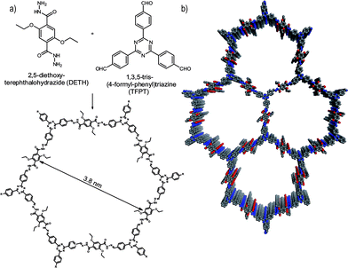
Herein, we report the first COF which is active in visible light induced hydrogen evolution in the presence of Pt as the proton reduction catalyst (PRC). Our hydrazone-based COF (TFPT–COF) is constructed from 1,3,5-tris-(4-formyl-phenyl)triazine (TFPT) and 2,5-diethoxy-terephthalohydrazide (DETH) building blocks (Fig. 1), featuring mesopores of 3.8 nm in diameter and the highest surface area among all hydrazone-based COFs reported so far.
Results and discussion
TFPT–COF: Synthesis and characterization
Triazine-based molecules offer high electron mobilities, electron withdrawing character28 and are hence widely used in synthetic chemistry29 and optoelectronics.28 TFPT has a much smaller dihedral angle between the phenyl and triazine unit (∼7.7°) compared to its benzene centered analogue (38.3°) (Fig. S1, ESI†).30 As a consequence, the use of TFPT should facilitate the formation of a planar COF with an extended π-system compared to the monomers and enhanced crystallinity. Indeed, the TFPT–COF turns out to be crystalline and at the same time stable in methanol and other solvents (Fig. S15, ESI†).TFPT–COF was synthesized by the acetic acid catalysed reversible condensation of the building blocks in dioxane–mesitylene (1![[thin space (1/6-em)]](https://www.rsc.org/images/entities/char_2009.gif) :
:![[thin space (1/6-em)]](https://www.rsc.org/images/entities/char_2009.gif) 2 v/v) at 120 °C in a sealed pressure vial under an argon atmosphere for 72 hours. The product was obtained as a fluffy pale-yellow nanocrystalline solid. To remove any starting material or solvent contained in the pores, TFPT–COF was centrifuged, washed with DMF and THF, soaked in DCM for 3 hours, and subsequently heated to 120 °C under a high dynamic vacuum for 12 h (10−7 mbar).
2 v/v) at 120 °C in a sealed pressure vial under an argon atmosphere for 72 hours. The product was obtained as a fluffy pale-yellow nanocrystalline solid. To remove any starting material or solvent contained in the pores, TFPT–COF was centrifuged, washed with DMF and THF, soaked in DCM for 3 hours, and subsequently heated to 120 °C under a high dynamic vacuum for 12 h (10−7 mbar).
It is worth mentioning that TFPT–COF could also be synthesized by in situ deprotection and subsequent condensation in a one-pot procedure (see Scheme S6, ESI†). Using this reaction scheme, the acetal protected TFPT is deprotected by treatment with a catalytic amount of camphorsulfonic acid in the solvent mixture. The COF formation is then started by adding the corresponding catalytic amount of sodium acetate to the reaction mixture. After 72 h, we obtained a material chemically and structurally identical to TFPT–COF (Fig. S2, ESI†). This protocol opens the door to a new variety of acetal-protected building blocks and at the same time enhances the solubility of otherwise insoluble building blocks due to the aliphatic protection group.
ATR-IR data of TFTP-COF show stretching modes in the range 1670–1660 cm−1 and 1201–1210 cm−1, which are characteristic of C![[double bond, length as m-dash]](https://www.rsc.org/images/entities/char_e001.gif) N moieties. The lack of the aldehyde Fermi double resonance at 2824 and 2721 cm−1, as well as the aldehyde carbonyl stretching vibration at 1700 cm−1 of the TFPT monomer clearly suggests the absence of any starting material. Furthermore, the triazine moiety is still present in the TFTP-COF as ascertained by the triazine semicircle stretch vibration at 806 cm−1 (Fig. S3†).
N moieties. The lack of the aldehyde Fermi double resonance at 2824 and 2721 cm−1, as well as the aldehyde carbonyl stretching vibration at 1700 cm−1 of the TFPT monomer clearly suggests the absence of any starting material. Furthermore, the triazine moiety is still present in the TFTP-COF as ascertained by the triazine semicircle stretch vibration at 806 cm−1 (Fig. S3†).
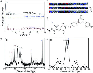
1H solid-state NMR MAS spectroscopy shows the presence of the ethoxy group through signals at 1.39 ppm (CH3–CH2–O) and 3.29 ppm (CH3–CH2–O) (Fig. 2e). The aromatic region is represented by a broadened signal at 6.5 ppm. Furthermore, the 13C CP-MAS spectrum clearly supports the formation of a hydrazone bond corresponding to the signal at 148.9 ppm, and confirms the presence of the triazine ring (167.9 ppm) (Fig. 2d). All other signals were also unambiguously assigned to the corresponding carbon atoms (Fig. 2c).18
Powder X-ray diffraction (PXRD) measurements confirm the formation of a crystalline framework with metrics being consistent with the structure model shown in Fig. 1. Comparison of the experimental data with the simulation31 reveal a hexagonal structure with P6/m symmetry and an eclipsed AA layer stacking, which is in line with most COF structures reported to date (Fig. 2a).7–11 Nevertheless, we assume that slight offsets with respect to the ideal cofacial layer stacking have to be taken into account as recently delineated by Heine,32 Dichtel and co-workers.33 Subtle layer offsets which are not resolvable by XRD result in the minimization of repulsive electrostatic forces between the layers with respect to the energetically less favorable, fully eclipsed structures. Nevertheless, whether the same situation also holds true for hydrazone COFs has yet to be demonstrated.
Pawley refinement (including peak broadening) of the experimental powder pattern gave lattice parameters of a = b = 41.90 Å (Fig. 2a and S5, ESI†). The theoretical powder pattern of the related staggered conformation derived from the gra net with P63/m symmetry does not reproduce the observed intensity distribution and was therefore discarded (Fig. 2a and S8, ESI†). The 001 diffraction peak at 2θ = 26.6 corresponds to an interlayer distance of 3.37 Å (Fig. 2b), suggesting a typical van der Waals contact between the aromatic layers. Interestingly, the presence of the ethoxy groups protruding into the pores does not notably increase the interlayer distance, thus indicating a predominantly coplanar arrangement with the plane of the honeycomb lattice.
According to the above theoretical studies and other predictions for the stacking of triazines by Gamez et al.,34 we have also simulated a parallel displaced structure (displacement vector 1.4 Å) with an AA′A-type stacking sequence (Fig. S9 and S10, ESI†). As expected, the simulated PXRD is very similar to both the experimental PXRD as well as the PXRD calculated for the perfectly eclipsed structure (Fig. S11, ESI†).
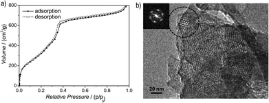
Argon sorption measurements at 87 K clearly show the formation of mesopores as indicated by a typical type IV adsorption isotherm (Fig. 3a). The Brunauer–Emmett–Teller (BET) surface area was calculated to be 1603 m2 g−1 (total pore volume is 1.03 cm3 g−1, Fig. S12, ESI†), which is the highest measured surface area among all hydrazone COFs reported to date.13–18,35 Comparing these values with those of COF-43, derived from a benzene-centered trigonal building block with the same pore size,18 the surface area has more than doubled, probably as a consequence of the smaller dihedral angle of the triazine-centered TFPT and the resulting more favorable stacking interactions, or due to the more complete activation of the material. The pore size distribution (PSD) was evaluated with non-local density functional theory (NLDFT). The experimental PSD exhibits a maximum at 3.8 nm, thereby verifying the theoretical pore diameter of 3.8 nm (Fig. S13, ESI†) which is the same pore size found by Yaghi and co-workers for their benzene-centered COF.18 Transmission electron microscopy images confirm the data derived from PXRD and sorption measurements. The hexagonal pore arrangement with pore distances of ≈3.4 nm is clearly visible, as well as the layered nanomorphology (Fig. 3b).
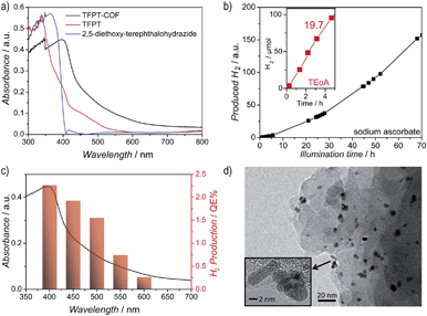
The diffuse reflectance UV/Vis spectrum of the yellow powder exhibits an absorption edge around 400 nm (the spike at 380 nm is due to a change of the light source), with the absorption tail extending well beyond 600 nm (Fig. 4a). We estimate an optical band gap of roughly 2.8 eV from the absorption edge, based on the Kubelka–Munk function (Fig. S14, ESI†). The TFPT–COF shows a pronounced red-shift of the absorption edge by 33 nm in comparison with the individual building blocks. A similar broadened and red-shifted absorption of the COF with respect to the monomers has been found by Jiang and co-workers for several COF systems.13,23–27 In principle, the observed HOMO–LUMO gap of the TFPT–COF is large enough to enable water splitting through band gap excitation and at the same time small enough to harvest a significant portion of the visible light spectrum.
To investigate this possibility, we studied the light-induced hydrogen evolution mediated by Pt-modified TFPT–COF in the presence of a sacrificial electron donor as the photocatalytic system under visible light irradiation. While TFPT–COF primarily acts as a photosensitizer for exciton generation, Pt functions as PRC. We previously demonstrated that the Pt-modified triazine-based carbon nitride poly(triazine imide) (PTI) shows substantial photocatalytic activity, despite its amorphous character.6 Therefore, the presence of triazine moieties in the TFPT–COF, along with a moderate band gap, renders this crystalline COF an excellent candidate to study hydrogen-evolution and possible structure–property relationships.
Photocatalytic hydrogen evolution
Hydrogen evolution was studied under standardized conditions and measured in the presence of the PRC Pt, using sodium ascorbate as sacrificial electron donor (see ESI† for details). In fact, TFPT–COF/Pt is a potent photocatalytic system, showing continuous and stable hydrogen production of 230 μmol h−1 g−1 (Fig. 4b and S22, ESI†). The total amount of hydrogen produced after 52 h (with sodium ascorbate) exceeds the total amount of hydrogen incorporated in the material (97.6 μmol), which adds evidence that hydrogen evolution is in fact catalytic and does not result from stoichiometric decomposition of the COF itself. Measurements in the dark (Fig. S22, ESI†) show no hydrogen evolution, confirming that the evolution of hydrogen is a photoinduced effect. The monomer TFPT alone does not show photocatalytic activity under these conditions either. The long-time stability was tested by catalyst cycling, i.e. centrifugation of the reaction mixture, washing of the precipitate and addition of fresh sodium ascorbate solution. Even after three cycles the hydrogen evolution does not decrease (Fig. S23, ESI†). Small fluctuations are due to small concentration differences of the COF/aqueous sodium ascorbate suspensions.Using a 10 vol% aqueous triethanolamine (TEOA) solution as sacrificial donor, an even higher hydrogen evolution rate was detected, with the amount of hydrogen evolved in the first five hours being as high as 1970 μmol h−1 g−1, corresponding to a quantum efficiency of 2.2%, while maximum QEs of up to 3.9% were obtained for individual batches (Fig. 4b). However, this high rate comes along with a quicker deactivation of the photocatalytic system. By reducing the amount of triethanolamine (1 vol%) and adjusting the suspension to pH = 7, stable hydrogen evolution for a longer time range (24 hours) was detected.
The observed high amount of hydrogen evolved under standard basic conditions (1970 μmol h−1 g−1) suggests that TFPT–COF/Pt is superior to Pt-modified amorphous melon, g-C3N4 (which was synthesized according to Zhang et al.5 at 600 °C) and crystalline poly(triazine imide) (720 μmol h−1 g−1, 840 μmol h−1 g−1 and 864 μmol h−1 g−1, respectively),6 which were tested under similar conditions for three hours with TEOA as sacrificial donor. We also studied oxygen evolution to probe whether full water splitting is possible with the TFPT–COF. However, no O2 could be detected under the conditions used (see ESI†).
Reconversion of TFPT–COF
After photocatalysis, the amorphous material was coated with dispersed Pt nanoparticles, formed in situ (Fig. 4d). The TEM images suggest that the material loses its long-range order during photocatalysis (Fig. 4d), which is supported by XRD measurements (Fig. 5 and S16, ESI†). This loss of long-range order has also been observed by Dichtel and co-workers and has been assigned to exfoliation of the COF in water.20 To test this hypothesis, we carried out sorption measurements and PXRD after photocatalysis (95 h of irradiation in sodium ascorbate solution). TFPT–COF/Pt was filtered off as a greenish solid (Fig. 5, inset picture, see ESI† for more images). A DCM extract of the solid catalyst did not contain any molecular material, which suggests that the as-obtained powder did not decompose and no monomers were released. At the same time, however, crystallinity was lost (Fig. S16, ESI†) and the BET surface area was reduced to 410 m2 g−1 (Fig. S18, ESI†). Nevertheless, we found that the amorphous product can easily be reconverted into the crystalline and porous TFPT–COF with a BET surface area of 1185 m2 g−1 (Fig. 5 and ESI†) by subjecting it to the initial synthesis conditions. Further experiments revealed that the TFPT–COF loses its long-range order during sonication in water. Overall, this observation strengthens the hypothesis that the COF is exfoliated in water,20 thereby losing its long-range order, while the connectivity and photoactivity is retained. | ||
| Fig. 5 Transformation of TFPT–COF during photocatalysis and subsequent recovery by reconversion (see ESI† for details). Inset photographs show colour change from yellow (TFPT–COF) to green (TFPT–COF/Pt). | ||
Conclusion
In conclusion, we have developed a new crystalline hydrazone-based TFPT–COF, which is the first COF to show photocatalytic hydrogen evolution under visible light irradiation in the presence of Pt as PRC. This framework is competitive with the best non-metal photocatalysts for hydrogen production and represents a lightweight, well-ordered model system, which in principle can be readily tuned – by replacement, expansion or chemical modification of its building blocks – to further study and optimize the underlying mechanism of hydrogen evolution mediated by the framework and to enhance its light harvesting capability. The triazine moieties in the TFPT–COF, which are likewise present in the recently developed triazine-based carbon nitride photocatalytic system PTI/Pt, may point to an active role of the triazine unit in the photocatalytic process.The development of COFs as tunable scaffolds for photocatalytic hydrogen evolution enables a general bottom-up approach toward designing tailor-made photosensitizers and photocatalysts with tunable optical and electronic properties, a goal we are currently pursuing in our lab. We expect this new application of COFs in photocatalysis to open new avenues to custom-made heterogeneous photocatalysts, and to direct and diversify the ongoing development of COFs for optoelectronic applications.
Acknowledgements
We thank S. Hug for sorption measurements, C. Stefani for PXRDs, V. Duppel for TEM measurements, D. Weber for general assistance, C. Minke for ssNMR measurements and M.-L. Schreiber for syntheses. Financial support by the Fonds the Chemischen Industrie (scholarship for L.S.), the cluster of excellence “Nanosystems Initiative Munich” (NIM) and the Center for NanoScience (CeNS) is gratefully acknowledged.Notes and references
- X. Chen, S. Shen, L. Guo and S. S. Mao, Chem. Rev., 2010, 110, 6503–6570 CrossRef CAS PubMed.
- H. Tong, S. Ouyang, Y. Bi, N. Umezawa, M. Oshikiri and J. Ye, Adv. Mater., 2012, 24, 229–251 CrossRef CAS PubMed.
- (a) S. Yanagida, A. Kabumoto, K. Mizumoto, C. Pac and K. Yoshino, J. Chem. Soc., Chem. Commun., 1985, 474–475 RSC; (b) J. Liu, S. Wen, Y. Hou, F. Zuo, G. J. O. Beran and P. Feng, Angew. Chem., Int. Ed., 2013, 52, 3241–3245 CrossRef CAS PubMed; (c) X. Wang, K. Maeda, A. Thomas, K. Takanabe, G. Xin, J. M. Carlsson, K. Domen and M. Antonietti, Nat. Mater., 2009, 8, 76–80 CrossRef CAS PubMed.
- K. Maeda, X. Wang, Y. Nishihara, D. Lu, M. Antonietti and K. Domen, J. Phys. Chem. C, 2009, 113, 4940–4947 CAS.
- J. Zhang, X. Chen, K. Takanabe, K. Maeda, K. Domen, J. D. Epping, X. Fu, M. Antonietti and X. Wang, Angew. Chem., Int. Ed., 2010, 49, 441–444 CrossRef CAS PubMed.
- K. Schwinghammer, B. Tuffy, M. B. Mesch, E. Wirnhier, C. Martineau, F. Taulelle, W. Schnick, J. Senker and B. V. Lotsch, Angew. Chem., Int. Ed., 2013, 52, 2435–2439 CrossRef CAS PubMed.
- A. P. Côté, A. I. Benin, N. W. Ockwig, M. O'Keeffe, A. J. Matzger and O. M. Yaghi, Science, 2005, 310, 1166–1170 CrossRef PubMed.
- H. M. El-Kaderi, J. R. Hunt, J. L. Mendoza-Cortes, A. P. Côté, R. E. Taylor, M. O'Keeffe and O. M. Yaghi, Science, 2007, 316, 268–272 CrossRef CAS PubMed.
- A. P. Côté, H. M. El-Kaderi, H. Furukawa, J. R. Hunt and O. M. Yaghi, J. Am. Chem. Soc., 2007, 129, 12914–12915 CrossRef PubMed.
- S.-Y. Ding and W. Wang, Chem. Soc. Rev., 2013, 42, 548–568 RSC.
- X. Feng, X. Ding and D. Jiang, Chem. Soc. Rev., 2012, 41, 6010–6022 RSC.
- Y. Du, K. Mao, P. Kamakoti, P. Ravikovitch, C. Paur, S. Cundy, Q. Li and D. Calabro, Chem. Commun., 2012, 48, 4606–4608 RSC.
- A. Nagai, X. Chen, X. Feng, X. Ding, Z. Guo and D. Jiang, Angew. Chem., Int. Ed., 2013, 52, 3770–3774 CrossRef CAS PubMed.
- X. Chen, M. Addicoat, S. Irle, A. Nagai and D. Jiang, J. Am. Chem. Soc., 2012, 135, 546–549 CrossRef PubMed.
- S. Wan, F. Gándara, A. Asano, H. Furukawa, A. Saeki, S. K. Dey, L. Liao, M. W. Ambrogio, Y. Y. Botros, X. Duan, S. Seki, J. F. Stoddart and O. M. Yaghi, Chem. Mater., 2011, 23, 4094–4097 CrossRef CAS.
- F. J. Uribe-Romo, J. R. Hunt, H. Furukawa, C. Klöck, M. O'Keeffe and O. M. Yaghi, J. Am. Chem. Soc., 2009, 131, 4570–4571 CrossRef CAS PubMed.
- M. G. Rabbani, A. K. Sekizkardes, Z. Kahveci, T. E. Reich, R. Ding and H. M. El-Kaderi, Chem.–Eur. J., 2013, 19, 3324–3328 CrossRef CAS PubMed.
- F. J. Uribe-Romo, C. J. Doonan, H. Furukawa, K. Oisaki and O. M. Yaghi, J. Am. Chem. Soc., 2011, 133, 11478–11481 CrossRef CAS PubMed.
- S.-Y. Ding, J. Gao, Q. Wang, Y. Zhang, W.-G. Song, C.-Y. Su and W. Wang, J. Am. Chem. Soc., 2011, 133, 19816–19822 CrossRef CAS PubMed.
- D. N. Bunck and W. R. Dichtel, J. Am. Chem. Soc., 2013, 135, 14952–14955 CrossRef CAS PubMed.
- T. P. King, S. W. Zhao and T. Lam, Biochemistry, 1986, 25, 5774–5779 CrossRef CAS.
- C. C. Lee, E. R. Gillies, M. E. Fox, S. J. Guillaudeu, J. M. J. Fréchet, E. E. Dy and F. C. Szoka, Proc. Natl. Acad. Sci. U. S. A., 2006, 103, 16649–16654 CrossRef CAS PubMed.
- S. Jin, X. Ding, X. Feng, M. Supur, K. Furukawa, S. Takahashi, M. Addicoat, M. E. El-Khouly, T. Nakamura, S. Irle, S. Fukuzumi, A. Nagai and D. Jiang, Angew. Chem., Int. Ed., 2013, 52, 2017–2021 CrossRef CAS PubMed.
- E. L. Spitler and W. R. Dichtel, Nat. Chem., 2010, 2, 672–677 CrossRef CAS PubMed.
- X. Ding, X. Feng, A. Saeki, S. Seki, A. Nagai and D. Jiang, Chem. Commun., 2012, 48, 8952–8954 RSC.
- X. Ding, J. Guo, X. Feng, Y. Honsho, J. Guo, S. Seki, P. Maitarad, A. Saeki, S. Nagase and D. Jiang, Angew. Chem., Int. Ed., 2011, 50, 1289–1293 CrossRef CAS PubMed.
- X. Ding, L. Chen, Y. Honsho, X. Feng, O. Saengsawang, J. Guo, A. Saeki, S. Seki, S. Irle, S. Nagase, V. Parasuk and D. Jiang, J. Am. Chem. Soc., 2011, 133, 14510–14513 CrossRef CAS PubMed.
- T. Ishi-i, K. Yaguma, T. Thiemann, M. Yashima, K. Ueno and S. Mataka, Chem. Lett., 2004, 33, 1244–1245 CrossRef.
- D. Sun, S. Ma, Y. Ke, D. J. Collins and H.-C. Zhou, J. Am. Chem. Soc., 2006, 128, 3896–3897 CrossRef CAS PubMed.
- (a) Z.-S. Li, J.-X. Chen, Y.-B. Huang, G.-R. Chen and T.-Y. Lan, Acta Crystallogr., Sect. E: Struct. Rep. Online, 2006, 62, 777–779 Search PubMed; (b) V. Volkis, E. Nelkenbaum, A. Lisovskii, G. Hasson, R. Semiat, M. Kapon, M. Botoshansky, Y. Eishen and M. S. Eisen, J. Am. Chem. Soc., 2003, 125, 2179–2194 CrossRef CAS PubMed.
- Material Studio v. 5.5.0.0, Accelrys Software Inc., 2011 Search PubMed.
- B. Lukose, A. Kuc and T. Heine, Chem.–Eur. J., 2011, 17, 2388–2392 CrossRef CAS PubMed.
- B. T. Koo, W. R. Dichtel and P. Clancy, J. Mater. Chem., 2012, 22, 17460–17469 RSC.
- (a) S. Grimme, Angew. Chem., Int. Ed., 2008, 47, 3430–3434 CrossRef CAS PubMed; (b) J. Antony, B. Alameddine, T. A. Jenny and S. Grimme, J. Phys. Chem. A, 2012, 117, 616–625 CrossRef PubMed; (c) T. J. Mooibroek and P. Gamez, Inorg. Chim. Acta, 2007, 360, 381–404 CrossRef CAS PubMed; (d) W. Pisula, H. Tsao, D. Dudenko, D. Cho, S. Puniredd, Y. Zhao, A. Mavrinskiy, J. Shu, M. Hansen, M. Baumgarten and K. Müllen, Polymers, 2013, 5, 833–846 CrossRef PubMed.
- (a) S. Chandra, S. Kandambeth, B. P. Biswal, B. Lukose, S. M. Kunjir, M. Chaudhary, R. Babarao, T. Heine and R. Banerjee, J. Am. Chem. Soc., 2013, 135, 17853–17861 CrossRef CAS PubMed; (b) S. Kandambeth, D. B. Shinde, M. K. Panda, B. Lukose, T. Heine and R. Banerjee, Angew. Chem., Int. Ed., 2013, 52, 13052–13056 CrossRef CAS PubMed; (c) S. Kandambeth, A. Mallick, B. Lukose, M. V. Mane, T. Heine and R. Banerjee, J. Am. Chem. Soc., 2012, 134, 19524–19527 CrossRef CAS PubMed.
Footnote |
| † Electronic supplementary information (ESI) available: Detailed experimental procedures, including syntheses of TFPT and TFPT–COF; PXRD patterns and simulations; FT-IR and additional CP-MAS NMR spectra; gas adsorption data; stability measurements, hydrogen evolution charts, hydrogen production cycles. See DOI: 10.1039/c4sc00016a |
| This journal is © The Royal Society of Chemistry 2014 |


