Enhancing the capacitive performance of a textile-based CNT supercapacitor
W. C. Lia,
C. L. Mak*a,
C. W. Kanb and
C. Y. Huib
aDepartment of Applied Physics, Hong Kong Polytechnic University, Hung Hom, Hong Kong. E-mail: apaclmak@polyu.edu.hk
bInstitute of Textile and Clothing, Hong Kong Polytechnic University, Hung Hom, Hong Kong
First published on 14th November 2014
Abstract
A metal layer, used as a current collector layer for a textile-based supercapacitor (SC), was prepared on polyethylene terephthalate (PET) fabrics using wet chemical methods. By integrating this additional current collector layer into the SC structure, the carbon-nanotube (CNT)-based SC showed an improved capacitive performance. The specific capacitances of the CNT/Cu/PET SC and CNT/Au/PET SC were 4.312 × 10⁻³ F cm−2 and 3.683 × 10⁻³ F cm−2 respectively, about 60 times larger than that obtained from the CNT/PET SC without the metal collector layer. On the other hand, the energy densities of these CNT-based SCs with metal layers were found to be ∼50 fold increased as compared to the CNT/PET SC. Similarly, the power densities of these two SCs with current collector layers were two orders of magnitude larger than that of CNT/PET SC. High flexibility was also demonstrated in these two metal-layered SCs. For the durability measurement, the CNT/Au/PET SC showed a stable performance, with its specific capacitance maintained at about 89% of its initial value after 2500 charge–discharge cycles. However, the CNT/Cu/PET SC only showed a relatively short-term stability, as its specific capacitance dropped to 12% of its initial value after 2500 charge–discharge cycles. In order to further improve its capacitive performance, polyaniline (PANI) was deposited on the CNT/Au/PET SC surface using a cyclic voltammetric deposition method. A specific capacitance of 0.103 F cm−2, about 30 times larger than that of the CNT/Au/PET SC, was obtained in the PANI/CNT/Au/PET SC which also showed good flexibility as well as high stability performance, with only 11% drop after 2500 charge–discharge cycles. On the basis of our results, we believe that by integrating a thin current collector layer into the textile-based CNT SC, its specific capacitance is enhanced while its flexibility and durability can be maintained. This method allows us to make any non-conducting fabric into a SC and turn it into a portable and wearable energy storage device.
Introduction
Owning to the development of portable and wearable electronics, fabrication of small, light and flexible energy storage devices becomes one of the hottest research topics in materials science.1–3 A supercapacitor (SC), also known as an electrochemical capacitor, provides a higher energy density than a conventional capacitor and is a promising candidate for wearable energy storage devices. Compared to batteries, it exhibits higher power density, faster charge–discharge rate, longer cycling lifetime and is safer. However, the energy density of a SC is usually much lower than that of the battery.1,4–9 Most of the recent studies on flexible SCs have focused on improving their energy densities as well as maintaining their high power densities and stability. For example, new carbon materials which provide a large surface area, such as carbon nanoparticles, carbon nanotubes (CNT) and graphene, have been used as the base electrodes as well as the current collector of SCs.3,4,9,13–15 These new carbon materials enhanced the specific capacitance of the SC. Studies also showed that by adding pseudocapacitive materials such as RuO2, MnO2 and NiO into CNT-based SCs, the specific capacitance and operation potential of the SC were increased.4,10–12 However, in these studies, the electrical conductivity of the SC has been overlooked. Compared with a metal layer, these carbon layers are not good current collector layers as the electrical conductivity of these carbon layers is usually lower than that of the metal layer.15,16 Indeed, in order to further increase the energy density of these SCs, a good current collector which can improve the collection and transport ability of electrons as well as reduce the energy loss due to internal resistance is needed.17,18As one of the main applications of these flexible SCs is used in energy storage for wearable electronic devices, fabrics would be a normal choice for being used as substrate. Other flexible substrates such as PET sheet,13 paper,17 and carbon cloth18 have been used as substrates for flexible SC, but all these substrates are not suitable to be used in clothing. Among various commercial fabrics, polyethylene terephthalate (PET) is common used in clothing as it possesses good strength, shrinkage resistance, chemical resistance, lustre, aesthetics, economics, consistency in quality and ready availability.19 It is a great challenge to obtain a metal current collector layer on the PET fabrics. The layer should be uniformly coated on the polymer fabrics, although the surface morphology of the polymer fabrics is very rough. Furthermore, the metal layer should be flexible but with good adhesion i.e. the metal layer cannot be too thick. Normally, there are two techniques to deposit a metal current collector on top of polymer fabrics i.e. physical or chemical deposition methods. Physical deposition methods such as screen print, sputtering and evaporation are commonly used.20–22 However, these physical deposition methods suffer from the weak adhesion of metal layer to the fabrics and uneven deposition arisen from the shadow effect. Conversely, wet chemical methods provide an effective way to deposit metal layer on fabrics. The chemical bonds that formed between the metal layer and the polymer fabrics usually results in better adhesion. With no shadow effect in chemical deposition, the metal layers are usually uniform. Furthermore, chemical methods are easily scaled up for large scale production without much cost.23–25
To enhance the capacitive performance of CNT-based SCs, addition of faradic materials is another common method. Transition metal oxides such as manganese oxide26 and conducting polymers27 have been employed to improve the capacitive performance of CNT-based SCs. However, transition metal oxides normally possess a poor electric conductivity and thus limit the SC to achieve high specific capacitance value.28 Conductive polymers, on the other hand, have higher conductivity. Polyaniline (PANI) is one of the conductive polymers with good electric conductivity, high specific capacitance and good capacitive retention abililty.29
In this paper, wet chemical plating methods were employed to fabricate metal current collector layer on PET fabrics. Afterward, CNT was dip-coated onto the metallized PET fabrics to fabricate a solid-state flexible CNT SC. Multi-wall CNT was used as the electrodes as they have large surface area, good chemical stability, reasonable electrical conductivity and mechanical properties.30,31 Compared to single-wall CNT, multi-wall CNT is normally cheaper. Mixture of polyvinyl alcohol/phosphoric acid (PVA/H3PO4) was used as the electrolyte as well as separator. The capacitive performance of the SC was characterized by cyclic voltammetry (CV). The galvanostatic charge–discharge and capacitance retention performance were also measured. In order to investigate how the metal current collector layer improved the capacitive performance, CNT-based SC on PET fabrics without any metal layers was also fabricated for comparison. In order to further enhance the performance of the CNT-based SC, PANI film was deposited on the CNT/Au/PET SC by a cyclic voltammetric deposition method. Its capacitive performance, galvanostatic charge–discharge and capacitance retention performance was also studied.
Experimental
PET fabrics were metallized using nickel electroless-plating and copper/gold electroplating methods. Before the metallization process, the fabrics were cut into samples with size of 10 × 10 cm2, and they were cleaned by detergent in ultrasonic bath to remove grease as well as dirt. A four-step metallization process including (1) surface modification, (2) activation, (3) Ni electroless plating and (4) Cu/Au electroplating was carried out. For surface modification, the cleaned samples were dipped into 6 M NaOH for 30 minutes to modify and roughen the surface. The samples were then dipped into 1% HCl for 30 seconds to neutralize excess NaOH that remained on the sample. Activation using Pd was carried out by dipping into a MACuPlex activator D-34 concentrate bath for 3 minutes, where the bath was prepared by mixing 774 ml of de-ionized water, 220 ml of 32% HCl, 20 ml of sensitizer-78 and 6 ml of MACuPlex activate D34C (Macdermid, solution of Pd/Sn2+ colloidal). In order to avoid the oxidation of Sn2+ into Sn4+, a metal cover was used to shield the light as well as moisture and dirt from the bath during the experiment. After that, the samples were dipped into a solution of 50 g l−1 H2SO4 at 50 °C for 1 minute to remove the Sn2+ ions from the Pd/Sn2+ colloidal and explode the Pd out for the reduction of Ni2+ to be taken place. The dipping time in H2SO4 should be controlled carefully. If the time is too short, the Sn2+ cannot be completely removed; if the time is too long, the Pd ions in the samples will be removed. To perform the Ni electroless plating, the samples were dipped into a MACuplex J-64 Ni bath, which was prepared by mixing 865 ml of de-ionized water, 5 ml of 28% of NH4OH, 100 ml of MACuPlex J-60 and 30 ml of MACuPlex J-61 (Macdermid), at 35 °C for 3 minutes in order to deposit the nickel layer on the activated PET fabrics. The thickness of the nickel layer was depended on the dipping time. In our experiments, dipping time of 3 minutes was employed so that the thickness of the Ni layer was about 0.02 μm. Before Cu/Au electroplating process, the samples were cleaned by electrolytic degreasing for 1.5–3 minutes. Non-cyanide alkaline copper bath was used for electroplating of copper and the plating process lasted for 2–3 minutes at 50 °C with 2–3 ASD (current density).Commercial multi-wall carbon nanotube (International Laboratory USA, 95%, 10–30 nm) was dispersed in water using sodium dodecylbenzenesulfonate (SDBS) as surfactant. Multi-wall CNT was used as the carbon material instead of double wall and single wall CNT because multi-wall CNT is much cheaper, even though its electric conductivity is not as good as the others. The concentrations for CNT and SDBS were 4 mg ml−1 and 0.4 mg ml−1 respectively. The CNT was uniformly dispersed in the solution using ultrasonic bath for 2 hours. 6 g of PVA powder (ACROS Organic, Mw: 95![[thin space (1/6-em)]](https://www.rsc.org/images/entities/char_2009.gif) 000) and 6 g of phosphoric acid (Sigma-Aldrich) were added into 60 ml DI water with stirring at 80 °C for 12 hours to form a PVA/phosphoric acid mixture gel which was used as the electrolyte. A simple dip-coating method was employed to synthesize the SCs. PET fabrics as well as metallized PET fabrics were dipped into the CNT ink and withdrawn slowly so that the ink was evenly coated on the fabrics surface. The fabrics were then dried at 80 °C for 15 minutes. This procedure was repeated for several times to ensure that the CNT was uniformly coated on the surface of the fabrics. Afterwards, the CNT coated fabrics were immersed into the 80 °C PVA/phosphoric acid electrolyte for 10 minutes. Two fabric samples were assembled together face to face to form a capacitor. The assembled sample was dried at room temperature for 12 hours until the excessive solution was evaporated completely.
000) and 6 g of phosphoric acid (Sigma-Aldrich) were added into 60 ml DI water with stirring at 80 °C for 12 hours to form a PVA/phosphoric acid mixture gel which was used as the electrolyte. A simple dip-coating method was employed to synthesize the SCs. PET fabrics as well as metallized PET fabrics were dipped into the CNT ink and withdrawn slowly so that the ink was evenly coated on the fabrics surface. The fabrics were then dried at 80 °C for 15 minutes. This procedure was repeated for several times to ensure that the CNT was uniformly coated on the surface of the fabrics. Afterwards, the CNT coated fabrics were immersed into the 80 °C PVA/phosphoric acid electrolyte for 10 minutes. Two fabric samples were assembled together face to face to form a capacitor. The assembled sample was dried at room temperature for 12 hours until the excessive solution was evaporated completely.
To study the effects of adding PANI into the SCs, PANI was deposited on the surface of CNT/Au/PET SC using cyclic voltammetric deposition method with a continuously potential scanning at 50 mV s−1 in the potential range from −0.2 to 1.2 V. 0.1 M aniline monomer (Sigma Aldrich 99.5%) and 0.5 M H2SO4 were used as the plating solution. Different numbers of cycles were performed to deposit a uniform green PANI coating on top of the electrode surface.
The surface morphology and cross-section of the samples were examined by an optical microscope (Nikon Microphot-FXA) equipped with a digital camera (Pixar), an environmental scanning electron microscope (Hitachi TM 3000) and a field emission scanning electron microscope (FESEM JEOL JSM-6335F). The cyclic voltammetry were carried out by using an electrochemical workstation (PARSTAT 2273, Princeton Applied Research) with scan rates between 10 mV s−1 and 200 mV s−1, and scan voltage ranging from 0 to 0.8 V. The galvanostatic charge–discharge and capacitance retention measurements were carried out by an electrochemical station CHI660C with current densities varied between 0.005 and 1 mA cm−2.
Results and discussion
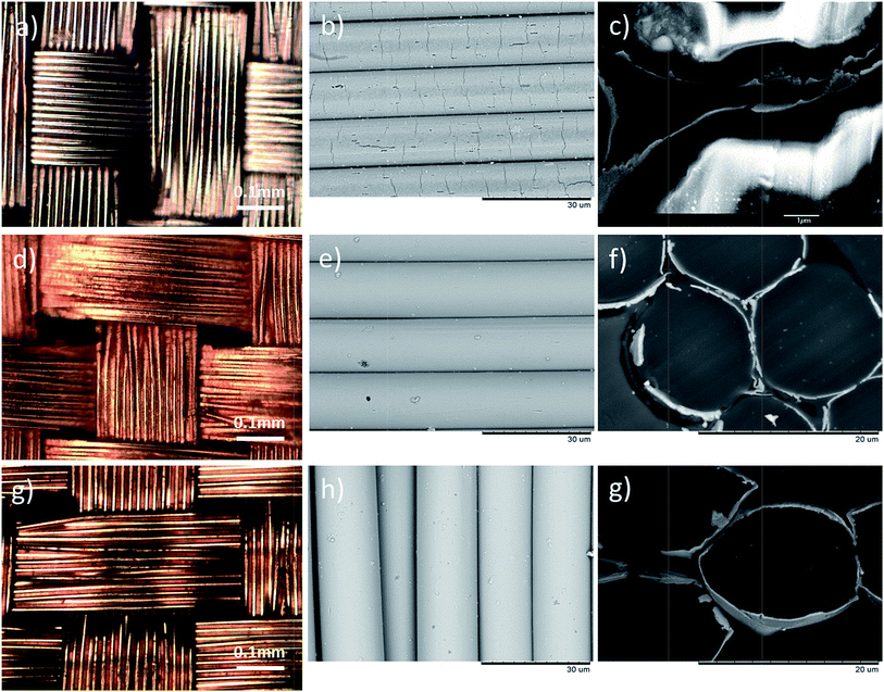
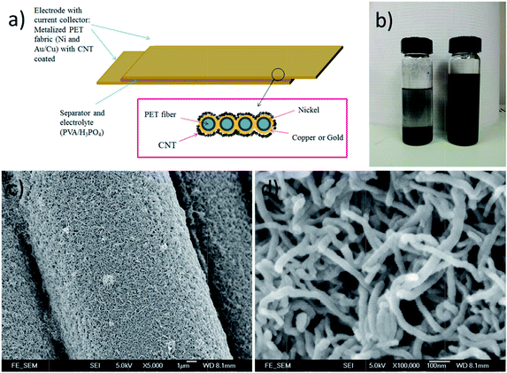
The qualities of the copper and gold layers depend on the qualities of the underlying electroless-plated nickel layer. Fig. 1a shows the surface morphology of the nickel plating. The coatings covered every single fiber individually and uniformly as shown in Fig. 1c. From the magnified micrograph (Fig. 1b), pitting sites and small cracks were observed on the surface. The pitting sites of size were about 1 μm. Indeed, these pitting sites, introduced by the etching process, roughened the surfaces and acted as anchors for the upper copper/gold layer. From the cross-section SEM micrograph (Fig. 1c), the thickness of the nickel coating was about 0.02 μm. By introducing this thin Ni layer, the fabrics became conductive and were able to carry out electroplating process. Fig. 1d and e show the surface morphology of the Cu-coated PET fabrics. The copper coatings were uniformly coated on every single fiber, and the coatings were adhered tightly on each individual fiber and no peeling off was noticed. Most of the cracks and the pitting sites were cover by the Cu or Au layer with only a few pitting sites were still observed. The thickness of the metal layer after the electroplating was about 0.2 μm (Fig. 1f) so that the flexibility of the PET fabrics was still preserved. Similarly, gold was also electroplated on the nickel coated PET fabrics. Fig. 1g and h show the surface morphologies of the samples at different magnifications. Similarly, the Au coatings were also adhered tightly on the fabrics without peeling off, and the thickness of the gold layer was about 0.2 μm. Again, the cross-section micrographs demonstrated that the metal coatings were thin and the flexibility was still preserved. Although the metallization procedure is quite complicated, the qualities of the metallized PET have high repeatability.Fig. 2a shows the schematic diagram of the textile-based CNT SC and Fig. 2b shows the effect of SDBS on the CNT ink. Without adding SDBS, two separated layers were observed (the left bottle in Fig. 2b), indicating that CNT was precipitated out from the ink. By adding SDBS, CNT was dispersed uniformly in the de-ionized water and was able to maintain in well-dispersed ink for few months. Fig. 2c shows the SEM micrograph of the CNT coated Cu/PET fabrics. CNT was uniformly deposited on the whole fabric and the diameter of the CNT was about 30 nm (Fig. 2d). They were tangled with each other, formed a porous network on the metallized fabrics, and provided large surface area. In our experiment, the thickness of the CNT coating was kept at ∼1 μm.
In this study, SCs with three different types of electrode were fabricated. They were (a) CNT electrode with no current collector (CNT/PET), (b) CNT electrode with copper current collector (CNT/Cu/PET) and (c) CNT electrode with gold current collector (CNT/Au/PET). CV scans were performed under different scan rates and the specific capacitance of SC was estimated from the curves using eqn (1):
| C = ∫idV/SvΔV | (1) |
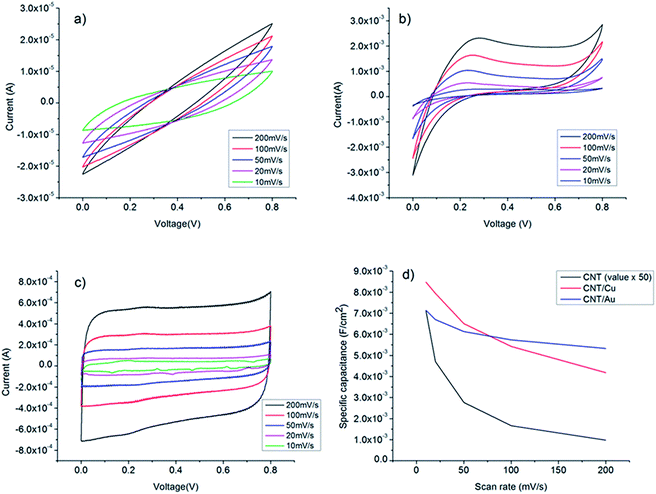 | ||
| Fig. 3 Cyclic voltammograms of (a) CNT/PET SC (b) CNT/Cu/PET SC (c) CNT/Au/PET SC at different scan rates. (d) Specific capacitance of the three SC at different scan rates. | ||
Another important measurement to evaluate the capacitive performance of SC is galvanostatic charge–discharge curve (Fig. 4). The specific capacitance can be calculated from the charge–discharge curve using eqn (2):
 | (2) |
 | (3) |
 | (4) |
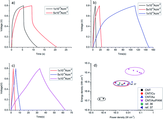 | ||
| Fig. 4 Galvanostatic charge–discharge curves of (a) CNT/PET SC, (b) CNT/Cu/PET SC and (c) CNT/Au/PET SC at different current densities. (d) Ragone plots of the SC. | ||
Fig. 4a shows the galvanostatic charge–discharge curves of the CNT/PET SC with two different current densities. The obtained specific capacitance were 6.875 × 10⁻⁵ F cm−2 and 7.5 × 10 −5 F cm−2 for current densities of 0.01 mA cm−2 and 0.005 mA cm−2 respectively. The asymmetry of the curves demonstrated that the SC behavior is not very good, and this is consistent with our previous results. The galvanostatic charge–discharge curves of the CNT/Cu/PET and the CNT/Au/PET SCs with current densities of 0.1 mA cm−2, 0.5 mA cm−2 and 1 mA cm−2 are shown in Fig. 4b and c respectively. Similarly, the curves of CNT/Cu/PET SC also showed an asymmetric shape, the charging time was longer than the discharging time, demonstrating an imperfect capacitive behavior.17,18 On the other hand, the curves of CNT/Au/PET SC showed a more symmetric and linear charging–discharging profile, demonstrating a better capacitive behavior. From Fig. 4, the obtained specific capacitances for CNT/Cu/PET SC at different current densities were 4.312 × 10⁻³ F cm−2, 3.526 × 10⁻³ F cm−2 and 2.653 × 10⁻³ F cm−2; while the specific capacitances for the CNT/Au/PET SC were 3.683 × 10⁻³ F cm−2, 3.381 × 10⁻³ F cm−2 and 3.175 × 10⁻³ F cm−2. Obviously, both metal current collectors increase the specific capacitance by about 60 times, similar to the results obtained in Fig. 3. Besides, the metal layer also improved the current–resistance drop (IR drop). The IR drop of CNT/PET SC was about 0.3 V at current density 0.01 mA cm−2; while the IR drops of CNT/Cu/PET and CNT/Au/PET SC were about 0.05 V and 0.01 V respectively. On the basis of these results, it is demonstrated that the metal current collector layer greatly improves the capacitive performance. Moreover, it enhances the energy density without sacrificing the power density of the SCs. Fig. 4d is the Ragone plot of different SCs. The highest energy densities of CNT/Cu/PET and CNT/Au/PET were 8.517 × 10⁻⁶ W h cm−3 and 8.183 × 10⁻⁶ W h cm−3 respectively. These energy densities were about 56 times and 54 times larger than the value of CNT/PET SC (1.528 × 10⁻⁷ W h cm−3), respectively; while their power densities (about 1 × 10⁻³ W cm−3) were 20 times larger than that of the CNT/PET SC (5 × 10⁻⁵ W cm−3). The energy density value of flexible SC with current collector are comparable to the solid state SCs, such as double-walled CNT SC (8 × 10⁻⁶ W h cm−3)35,36 and single-walled CNT SC (10 × 10−5 W h cm−3).35,37 These demonstrated that the current collector can enhance the energy store of the multi-walled CNT SC comparable with the double-walled and single-walled SCs.
For practical applications, the stability of SCs is an important factor. Gao et al. demonstrated that MWCNT SCs have a excellent cyclic stability.31 The SC device can remain 99.9% after 1000 cycles. In Fig. 5, we studied the cycling performance of the other two SCs by measuring their charge–discharge curves for 2500 cycles. The CNT/Cu/PET SC in Fig. 5a show a poor stability. The specific capacitance dropped significantly after 100 cycles and settled at 12% for the remaining cycles. We suggest that the poor stability might be due to the interaction of copper layers with the electrolyte. This reaction might be occurred during the charge–discharge cycle and is probably non-reversible. Further investigation will be required in order to confirm this suggestion. Although, the copper can enhance the capacitance performance, this improvement cannot last long which is not suitable for devices application. Nevertheless, the CNT/Au/PET SC shows a more stable performance (Fig. 5b). The specific capacitance slowly decayed to 89% of the initial value and remained almost constant for the remaining 2500 cycles. Thus, gold layer is much more suitable to be the metal current collector for enhancing capacitive performance.
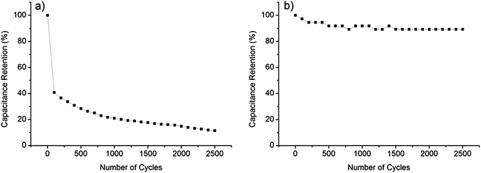 | ||
| Fig. 5 (a) Cycling performance of CNT/Cu/PET SC at current density 0.5 mA cm−2. (b) Cycling performance of CNT/Au/PET SC at current density 0.5 mA cm−2. | ||
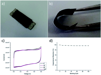
Being a portable and wearable energy storage device, both flexibility and safety are very important. In Fig. 6b, the CNT/Au/PET SC was able to be bended in any angles without losing its performance, showing its high flexible property. CV curves were measured under various bending angles and the specific capacitance of the SC (Fig. 6c) were almost the same for different bending angles. The CV curves were in rectangular shape, and the sizes are nearly the same in various bending angles, demonstrating that the deformation would not affect the capacitive performance of the SC. Repeated bending cycles test was used to evaluate the capacitive performance. Our results show that the retention is maintained at 97% after 100 bending cycles which demonstrated that the bending cycles also would not affect the capacitive performance of the SC. Therefore, our results show that this textile-based flexible SC is suitable for being a portable and wearable energy storage device.
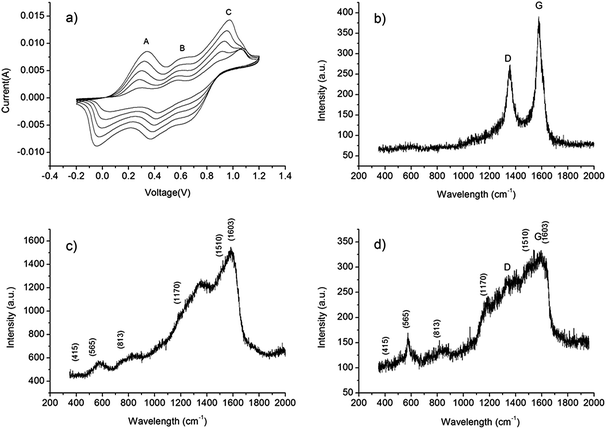
In order to further enhance the specific capacitance of the CNT/Au/PET SC, PANI was deposited on the surface using a CV growth method with 10, 20, 40 and 60 CV growth cycles. Fig. 7a shows the CV growth of the PANI in the range of −0.2 V to 1.2 V with scan rate at 50 mV s−1. Three peaks at 0.3 V (A), 0.55 V (B) and 0.95 V (C) were observed: peak A is the radical cation formation peak, peak B is the head-to-tail dimmer oxidation peak and peak C is the emeraldine to pernigraniline conversion peak.38 When the number of deposit cycle increases, the area becomes larger, indicating that more PANI had been deposited, resulting a higher capacitive ability of the SC. After the growth of PANI, the SC was covered with a green coating. Raman spectroscopy was employed to verify the successfully growth of PANI. Fig. 7b shows the Raman spectrum of the CNT/Au/PET SC, and two sharp peaks were observed. The peak at 1350 cm−1, assigned as D band, is the disorder band or defeat band of CNT. It represents a ring breathing mode from sp2 carbon rings. On the other hand, the peak at 1582 cm−1, called G band, is designated as the primary mode in CNT. This mode represents the planar configuration sp2 bonded carbon that constitutes the CNT.39
Fig. 7c and d show the Raman spectra of PANI/Au/PET and PANI/CNT/Au/PET SC, respectively. In general, these two spectra were very similar. The peaks at 416 cm−1 and 565 cm −1 represent C–N–C out of plane deformation modes and the deformation mode of protonated amine groups, respectively. The peak at 813 cm −1 is assigned as a mixture of various torsion angles between the two aniline rings of the PANI structure. The peaks between 1000 cm−1 and 1700 cm−1 represent the PANI oxidation state. For example, the peaks at 1170 cm−1, 1510 cm−1 and 1603 cm−1 represent the C–H deformation band of the benzoid ring, the N–H bending deformation band of protonated amine, and the C–C deformation band of benzoid ring, respectively.40 Although with a much weaker signal-to-noise ratio, the Raman spectrum shown in Fig. 7d was nearly the same as the spectrum in Fig. 7c, indicating that all the characteristic peaks of PANI were observed. Thus, we believe that PANI was successfully deposited on the CNT/Au/PET SC.
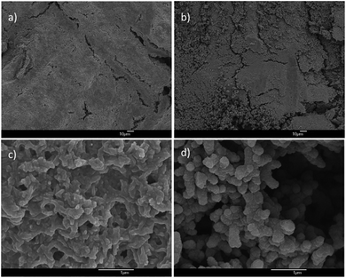
Different growth cycles of PANI (10, 20, 40 and 60 cycles) were deposited to study the effect of PANI growth cycle on the capacitive performance. Fig. 8 present the SEM micrographs of the PANI with different growth cycles. Fig. 8a and b show the large area SEM images of the PANI with 10 and 60 growth cycles, respectively. In general, PANI was completely covered the CNT surface with some cracks. Compare with the 10 growth cycle sample, more cracks with PANI peeling off from the surface of the 60 growth cycle sample. This might be due to the poor adhesion between the PANI and CNT. When the growth cycle was increased, the PANI film grew thicker and peeled off easily and this phenomenon was observed at the 40 and 60 growth cycles. Fig. 8c and d show the magnified SEM image, a porous structure of PANI was observed. The high surface area and the faradic properties of the PANI can increase the capacitance of the SCs. However, the morphologies of the PANI in different samples were different. For the 10 cycle growth sample, the PANI was in flakes shape and became granular like when the growth cycles increased to 60.
As mentioned before, the PANI started to peel off after 40 growth cycles. Therefore, 10 and 20 CV growth cycles were used to make the PANI/CNT/Au/PET SCs. To evaluate the thickness of the PANI coating, cross section SEM image were taken. The thickness of PANI in 10 CV cycles and 20 CV cycles were 4 μm (Fig. 9a) and 6.5 μm (Fig. 9b) respectively. Our studies only focused on 10 and 20 cycles, as the growth cycles is further increase, the flexibility of the SC would become poorer.
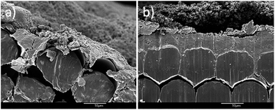 | ||
| Fig. 9 Cross section image of PANI coated fabric (a) in 10 CV growth cycles and (b) 20 CV growth cycles. | ||
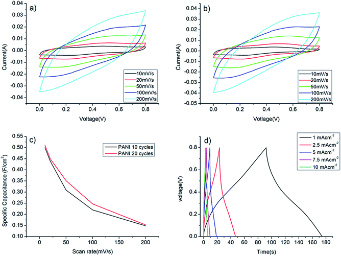
The capacitance performances of PANI/CNT/Au/PET SC were evaluated using the cyclic voltammetry within a potential range between 0 V and 0.8 V. Fig. 10a and b show the CV curves of the PANI/CNT/Au/PET SC with 10 CV growth cycles and 20 CV growth cycles respectively. The shape and area of the curves are more or less the same. The curves were deteriorated from the nearly rectangular shape (Fig. 3c) to an ellipsical shape. This might due to the delay of potential from the pseudofaradic reaction of PANI or the resistivity becomes higher after the deposition of the PANI.32 Although the shape was deteriorated, the current was greatly enhanced by an order of magnitude. The specific capacitances at different scan rates were calculated and the results were shown in Fig. 10c. As expected, the specific capacitances were larger at slower scan rate, and the largest values for PANI/CNT/Au/PET SC of 10 and 20 growth cycles were about 0.5 F cm−2 and 0.51 F cm−2, respectively. Our results indicated that the capacitance does not change much with the increase in the growth cycle. Comparing with the value obtained in Fig. 3d, the specific capacitance was 100 times larger than that of the CNT/Au/PET SC and 3570 times larger than that of the CNT/PET SC. It demonstrated that the capacitive performance of the textile-based SC was greatly improved by adding PANI as active material. To further evaluate the capacitive performance, galvanostatic charge–discharge curves were measured within the potential range of 0 V to 0.8 V in different current densities and the results are shown in Fig. 10d. The calculated specific capacitance are 0.103 F cm−2, 0.074 F cm−2, 0.061 F cm−2, 0.045 F cm−2 and 0.039 F cm−2 for current density of 1 × 10⁻³ A cm−2, 2.5 × 10⁻³ A cm−2, 5 × 10⁻³ A cm−2, 7.5 × 10⁻³ A cm−2, and 1 × 10⁻² A cm−2 respectively. The charge–discharge curve shows highly symmetric shape and this indicates that the device has a good capacitive behavior. The IR drop was about 0.04 V which was higher than that in CNT/Au/PET (0.01 V). The energy density and power density were calculated from the charge–discharge curves and the results are shown in Fig. 4d. The PANI/CNT/Au/PET SC exhibit the largest energy density at about 2.412 × 10⁻⁴ W h cm−3 with a power density of 0.011 W cm−3. The energy density is 28 times larger than the CNT/Au/PET SC, indicating that the PANI enhances the energy storage capacity.
The stability performance of the PANI/CNT/Au/PET SC was investigated at a current density of 1 mA cm−2 and the results were shown in Fig. 11a. The capacitance retained about 89% after 2500 cycles of the galvanostatic charge–discharge process, indicating the good stability of this SC. Fig. 11b shows the CV curves of the SC at different bending angles. The CV curves were almost overlapping with each other, indicating the excellent performance under bending stress of this SC.
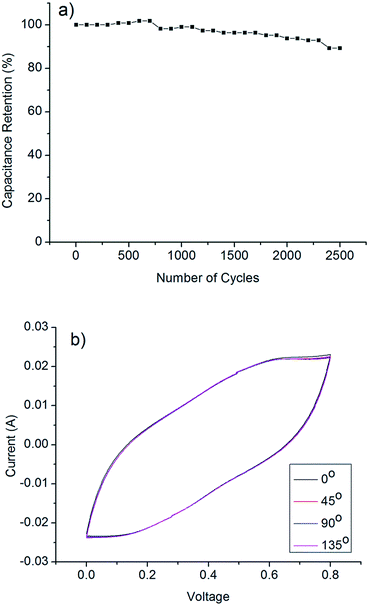 | ||
| Fig. 11 (a) Cycling performance of PANI/CNT/Au/PET SC at current density of 1 mA cm−2 (b) cyclic voltammograms of the supercapacitor at 100 mV s−1 scan rate in different bending curvature. | ||
Conclusion
Solid-state flexible SCs on textile-based substrates were successfully fabricated by simple wet chemical and dip-coating methods. A thin layer of metal was used for the current collector layer for the SCs. It provided a fast electron transport and improved the charge collection capacity of the CNT-based electrode. Our results showed that this metal layer improved the specific capacitance by about 60 times as compared to the SC without the metal layer. The capacitance retention study showed that the CNT/Cu/PET SC dropped significantly to 12% of the initial value which might due to reaction existed in the copper electrodes. For the CNT/Au/PET SC, it showed a more stable performance which only dropped by 11% after 2500 charge–discharge cycles. A large energy density and a high power density were maintained in these metal layered SC. On the basis of our studies, the Au layer will be a suitable current collector material to achieve a large energy density, high power density and long life time capacitive device. In addition, PANI was added on top of the CNT/Au/PET SC by a simple CV deposition method and the specific capacitance was further enhanced by 30 times. This PANI based SC showed a good stability performance, only 11% drop after the 2500 charge–discharge cycles. It also showed excellent performance under bending stress. These outstanding performances reveal that PANI/CNT/Au/PET is a great potential energy storage device for the flexible and wearable electronic.Notes and references
- P. Simon and Y. Gogotsi, Materials for electrochemical capacitor, Nat. Mater., 2008, 7, 845–854 CrossRef CAS PubMed
.
- J. F. Ihlefeld, P. G. Clem, B. L. Doyle, P. G. Kotula, K. R. Fenton and C. A. Apblett, Fast Lithium-Ion Conducting Thin-Film Electrolytes Integrated Directly on Flexible Substrates for High-Power Solid-State Batteries, Adv. Mater., 2011, 23, 5663–5667 CrossRef CAS PubMed
.
- X. Xiao, T. Li, P. Yang, Y. Gao, H. Jin, W. Ni, W. Zhan, X. Zhang, Y. Cao, J. Zhong, L. Gong, W. C. Yen, W. Mai, J. Chen, K. Huo, Y. L. Chueh, Z. L. Wang and J. Zhou, Fiber-Based All-Solid-State Flexible Supercapacitors for Self-Powered Systems, ACS Nano, 2012, 6(10), 9200–9206 CrossRef CAS PubMed
.
- G. Yu, L. Hu, N. Liu, H. Wang, M. Vosgueritchian, Y. Yang, Y. Cui and Z. Bao, Enhancing the supercapacitor performance of graphene/MnO2 nanostructured electrodes by conductive wrapping, Nano Lett., 2011, 11, 4438–4442 CrossRef CAS PubMed
.
- B. E. Conway, Electrochemical Supercapacitors: Scientific Fundamentals and Technological Applications, Kluwer Academic/Plenum, New York, 1999 Search PubMed
.
- M. Winter and R. J. Brodd, What are batteries, fuel cells and supercapacitors, Chem. Rev., 2005, 105, 1021 CrossRef CAS
.
- L. L. Zhang and X. S. Zhao, Carbon-based materials as supercapacitor electrodes, Chem. Soc. Rev., 2009, 28, 2520–2531 RSC
.
- A. S. Arico, P. Bruce, B. Scrosati, J. M. Tarascon and W. Van Schalkwijk, Nanostructured materials for advanced energy conversion and storage devices, Nat. Mater., 2005, 4, 366–377 CrossRef CAS PubMed
.
- W. Chen, R. B. Rakhi, L. Hu, X. Xie, Y. Cui and H. N. Alshareef, High-Performance Nanostructured Supercapacitors on a Sponge, Nano Lett., 2011, 11, 5165–5172 CrossRef CAS PubMed
.
- T. Cottineau, M. Toupin, T. Delahaye, T. Brousse and D. Belanger, Nanostructured transition metal oxides for aqueous hybrid electrochemical supercapacitors, Appl. Phys. A: Mater. Sci. Process., 2006, 82, 599–606 CrossRef PubMed
.
- M. Toupin, T. Brousse and D. Belanger, Charge Storage Mechanism of MnO2 Electrode Used in Aqueous Electrochemical Capacitor, Chem. Mater., 2004, 16, 3184–3190 CrossRef CAS
.
- D. W. Wang, F. Li and H. M. Cheng, Hierarchical porous nickel oxide and carbon as electrode materials for asymmetric supercapacitor, J. Power Sources, 2008, 185, 1563–1568 CrossRef CAS PubMed
.
- Y. Gao, Y. S. Zou, W. Xiong, L. J. Jiang, M. Mahjouri-samani, P. Thirugnanam, X. Huang, M. M. Wang, L. Jiang and Y. F. Lu, Transparent, flexible, and solid-state supercapacitors based on graphene electrodes, APL Mater., 2013, 1, 012101 CrossRef PubMed
.
- S. Hu, R. Rajamani and X. Yu, Flexible solid-state paper based carbon nanotube supercapacitor, Appl. Phys. Lett., 2012, 100, 104103 CrossRef PubMed
.
- P. Chen, H. Chen, J. Qiu and C. Zhou, Inkjet printing of single-walled carbon nanotube/RuO2 nanowire supercapacitors on cloth fabrics and flexible substrate, Nano Res., 2010, 3(8), 594–603 CrossRef CAS PubMed
.
- X. Gan, Y. Wu, L. Liu, B. Shen and W. Hu, Electroless plating of Cu–Ni–P alloy on PET fabrics and effect of plating parameters on the properties of conductive fabrics, J. Alloys Compd., 2008, 455, 308–313 CrossRef PubMed
.
- L. Yuan, X. Xiao, T. Ding, J. Zhong, X. Zhang, Y. Shen, B. Hu, Y. Huang, J. Zhou and Z. L. Wang, Paper-Based Supercapacitor for Self-Powered Nanosystems, Angew. Chem., Int. Ed., 2012, 51, 1–6 CrossRef
.
- X. Lu, T. Zhai, X. Zhang, Y. Shen, L. Yuan, B. Hu, L. Gong, J. Chen, Y. Gao, J. Zhou, Y. Tong and Z. L. Wang, WO3−x@Au@MnO2 Core–Shell Nanowires on Carbon Fabric for High-Performance Flexible Supercapacitors, Adv. Mater., 2012, 24(7), 938–944 CrossRef CAS
.
- N. Pan, K. Chen, C. J. Moneg and S. Backer, Studying the Mechanical Properties of Blended Fibrous Structures Using a Simple Model, Text. Res. J., 2000, 70(6), 502–507 CrossRef CAS PubMed
.
- C. T. Wan, K. A. Taylor, D. L. Chambers and G. T. Susi, Met. Plast., 1991, 2, 81 Search PubMed
.
- K. De Bruyn, M. Van Stappen, H. De Deurwaerder, L. Rouxhet and J. P. Celis, Study of pretreatment methods for vacuum metallization of plastics, Surf. Coat. Technol., 2003, 163(164), 710–715 CrossRef
.
- Y. Dietzel, W. Przyborowski, G. Nocke, P. Offermann, F. Hollstein and J. Meinhardt, Investigation of PVD arc coating on polyamide fabrics, Surf. Coat. Technol., 2000, 135(1), 75–81 CrossRef CAS
.
- C. S. Ng, C. L. Mak and Y. W. Wong, Wet pre-treatment of poly(butylene) terephthalate–poly(ethylene) terephthalate blend and subsequent metallization by electroplating, Phys. Status Solidi, 2008, 11, 3535–3540 CrossRef
.
- M. Charbonnier, M. Romand and Y. Goepfert, Ni direct electroless metallization of polymers by a new palladium-free process, Surf. Coat. Technol., 2006, 200, 5028–5036 CrossRef PubMed
.
- M. Charbonnier, M. Romand, Y. Goepfert, D. Leonard, F. Bessueille and M. Bouadi, Palladium (+2) reduction: A key step for the electroless Ni metallization of insulating substrates by a tin-free process, Thin Solid Films, 2007, 515(4), 1623–1633 CrossRef PubMed
.
- K. W. Nam, C. W. Lee, X. Q. Yang, B. W. Cho, W. S. Yoon and K. B. Kim, Electrodeposited manganese oxides on three-dimensional carbon nanotube substrate: Supercapacitive behaviour in aqueous and organic electrolytes, J. Power Sources, 2009, 188(1), 323–331 CrossRef CAS PubMed
.
- H. L. Wang, Q. L. Hao, X. J. Yang, L. D. Lu and X. Wang, Graphene oxide doped polyaniline for supercapacitors, Electrochem. Commun., 2009, 11(6), 1158–1161 CrossRef CAS PubMed
.
- Y. Hou, Y. W. Cheng, T. Hobson and J. Liu, Design and Synthesis of Hierarchical MnO2 Nanospheres/Carbon Nanotubes/Conducting Polymer Ternary Composite for High Performance Electrochemical Electrodes, Nano Lett., 2010, 10, 2727–2733 CrossRef CAS PubMed
.
- K. Wang, Q. H. Meng, Y. J. Zhang, Z. X. Wei and M. H. Miao, High-Performance Two-Ply Yarn Supercapacitors Based on Carbon Nanotubes and Polyaniline Nanowire Arrays, Adv. Mater., 2013, 25, 1494–1498 CrossRef CAS PubMed
.
- C. S. Du and N. Pan, Carbon Nanotube-based Supercapacitors, Nanotechnol. Law Bus., 2007, 4, 3–10 Search PubMed
.
- K. Gao, Z. Shao, X. Wang, Y. Zhang, W. Wang and F. Wang, Cellulose nanofibers/multi-walled carbon nanotube nanohybrid aerogel for all-solid-state flexible supercapacitors, RSC Adv., 2013, 3, 15058–15064 RSC
.
- E. Frackowiak and F. Beguin, Carbon materials for the electrochemical storage of energy in capacitors, Carbon, Pergamon, 2001, vol. 39, pp. 937–950 Search PubMed
.
- H. B. Li, M. H. Yu, F. X. Wang, P. Liu, Y. Liang, J. Xiao, C. X. Wang, Y. X. Tong and G. W. Yang, Amorphous nickel hydroxide nanospheres with ultrahigh capacitance and energy density as electrochemical pseudocapacitor materials, Nat. Commun., 2013, 4, 1894 CrossRef CAS PubMed
.
- H. Gao, F. Xiao, C. B. Ching and H. Duan, High-Performance Asymmetric Supercapacitor Based on Graphene Hydrogel and Nanostructured MnO2, ACS Appl. Mater. Interfaces, 2012, 4, 2801–2810 Search PubMed
.
- X. Lu, M. Yu, G. Wang, T. Zhai, S. Xie, Y. Ling, Y. Tong and Y. Li, H-TiO2@MnO2//H-TiO2@C Core–Shell Nanowires for high performance and flexible asymmetric supercapacitors, Adv. Mater., 2013, 25(2), 267–272 CrossRef CAS PubMed
.
- Y. J. Kang, H. Chung, C. H. Han and W. Kim, All-solid-state flexible supercapacitors based on papers coated with carbon nanotubes and ionic-liquid-based gel electrolytes, Nanotechnology, 2012, 23, 065401 CrossRef PubMed
.
- M. Kaenpgen, C. K. Chan, J. Ma, Y. Cui and G. Gruner, Printable Thin film supercapacitors using single-walled carbon nanotubes, Nano Lett., 2009, 9(5), 1872–1876 CrossRef PubMed
.
- J. Zhang, L. B. Kong, B. Wang, Y. C. Luo and L. Kang, In situ electrochemical polymerization of multi-walled carbon nanotube/polyaniline composite films for electrochemical supercapacitors, Synth. Met., 2009, 159, 260 CrossRef CAS PubMed
.
- J. Hodkiewicz, Characterizing Graphene with Raman Spectroscopy, Thermo Scientific application note, 2010 Search PubMed
.
- J. Benson, I. Kovalenko, S. Boukhalfa, D. Lashmore, M. Sanghadasa and G. Yushin, Multifunctional CNT-Polymer Composites for Ultra-Tough Structural Supercapacitors and Desalination Devices, Adv. Mater., 2013, 25, 6625–6632 CrossRef CAS PubMed
.
| This journal is © The Royal Society of Chemistry 2014 |

