Effect of support and solvent on the activity and stability of NiCoB amorphous alloy in cinnamic acid hydrogenation

Guoyi Bai *, Huixian Dong , Zhen Zhao , Hailong Chu , Xin Wen , Chen Liu and Fei Li
Key Laboratory of Chemical Biology of Hebei Province, College of Chemistry and Environmental Science, Hebei University, Baoding 071002, PR China. E-mail: baiguoyi@hotmail.com; Fax: +86-312-5937102; Tel: +86-312-5079359

Received 3rd March 2014 , Accepted 15th April 2014

First published on 16th April 2014


Abstract

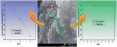
Selective hydrogenation of cinnamic acid was studied over different supported NiCoB amorphous alloys; a γ-Al2O3 supported NiCoB catalyst showed particularly good activity. The application of ultrasound during catalyst preparation was found to make the Ni active sites more dispersed, thus enhancing the catalyst activity. The NiCoB/γ-Al2O3-u catalyst so obtained could be recycled effectively for nine runs in tert-butanol, in contrast it deactivated after only three runs in water. XPS, SEM and XRD characterizations indicated that loss of Ni and hydration of the γ-Al2O3 support were the main reasons for catalyst deactivation in water. Thus, an efficient and stable catalytic system involving NiCoB/γ-Al2O3-u and tert-butanol was established for cinnamic acid hydrogenation in this study.

1. Introduction

NiB amorphous alloys have attracted much interest due to their special properties such as short-range order and long-range disorder1 and have been widely employed in catalytic hydrogenation.2–5 For instance, Fang et al. have studied the effect of Cr doping on a NiB amorphous alloy catalyst for 2-ethylanthraquinone hydrogenation and found that the doped catalyst exhibited higher selectivity for 2-ethylanthrahydroquinone reduction than the undoped one.3 Unfortunately, most of these pure NiB amorphous alloys deactivated quickly and usually could not be recycled in a second run.

As is well known, stability is an important character for a good industrial catalyst and much effort has been devoted to achieve this.6–9 Specific to NiB amorphous alloy catalysts, loading the active species on a support is regarded as an effective method to improve their stability.10,11 For instance, Liu et al. have reported that a NiB amorphous alloy supported on boehmite exhibited superior activity and relatively good stability over four runs in the selective hydrogenation of p-nitrophenol and p-chloronitrobenzene.11 However, there is still a lack of NiB amorphous alloys with sufficient stability, which of course limits their applications in industry.

Very recently, we have prepared a Co-modified NiB amorphous alloy catalyst for the selective hydrogenation of cinnamic acid to hydrocinnamic acid,12 which is an important chemical intermediate.13,14 This catalyst showed excellent catalytic performance in this reaction, similar to that of Pd-based noble metal catalysts,15,16 but it also exhibited poor stability during recycling. Consequently, in an effort to find a suitably active and stable catalyst for this transformation, various solid supports were examined in combination with this type of NiCoB amorphous alloy catalyst. The effects of solvent on the stability of such supported NiCoB catalysts were also examined to search for optimal reaction conditions for this hydrogenation. This has resulted in the identification of a NiCoB/γ-Al2O3-u catalyst, which shows both suitable activity and stability, when used in tert-butanol, for the selective hydrogenation of cinnamic acid.

2. Experimental

2.1. Catalyst preparation

The supported NiCoB amorphous alloys were prepared by an impregnation-reduction method. The support S (S: TiO2, activated carbon (AC), ZSM-5, Hβ, γ-Al2O3, 2.0 g) was first calcined at 773 K for 4 h and then impregnated with an aqueous solution of 0.415 g (0.9 M) NiCl2·6H2O and 0.042 g (0.09 M) CoCl2·6H2O (molar ratio Ni[thin space (1/6-em)]:[thin space (1/6-em)]Co = 10[thin space (1/6-em)]:[thin space (1/6-em)]1). The resulting paste was then dried at 393 K for 2 h. The resulting precursor was reduced by adding 7 mL of 1.0 M aqueous KBH4 containing 0.2 M NaOH dropwise with vigorous stirring while cooling in an ice bath to furnish a black precipitate. This was filtered off and washed with deionized water several times, followed by absolute ethanol three times. The catalyst so obtained (denoted as NiCoB/S) was kept under absolute ethanol for future use. When ultrasound was applied during the preparation process, the catalyst thus obtained was denoted as NiCoB/S-u. NiCoB catalyst was prepared by a chemical reduction method as described previously.12

2.2. Catalyst characterization

Bulk compositions of the supported amorphous alloy catalysts were identified by inductively coupled plasma analysis (ICP) using a VISTA-MPX spectrometer. Brunauer–Emmett–Teller (BET) surface areas of the catalysts were measured by nitrogen physisorption at 77 K on a Micromeritics Tristar II 3020 surface area and pore analyzer. Powder X-ray diffraction (XRD) patterns were accumulated with a Bruker D 8 diffractometer using a Cu Kα radiation source at 40 kV and 40 mA with a step size of 0.01° 2θ over the range 10 to 80°. Scanning electron microscopy (SEM) was performed on a JEOL JSM-7500 electron microscope. Transmission electron microscope (TEM) images and selected area electron diffraction (SAED) were measured on a JEOL JEM-2100F microscope. H2-chemisorption and temperature-programmed desorption measurements of hydrogen (H2-TPD) were tested using a TP-5000 instrument equipped with a thermal conductivity detector supplied by Xianquan Co. Ltd. X-ray photoelectron spectroscopy (XPS) analysis was carried out on a PHI 1600 spectrometer using monochromatic Mg Kα as the excitation source.

2.3. Catalyst activity test

Cinnamic acid hydrogenation was carried out as follows: cinnamic acid (3.0 g), catalyst (0.3 g) and solvent (60 mL) were mixed in a 100 mL stainless steel autoclave equipped with a mechanical stirrer and electric heating system. The reactor was filled with H2 three times followed by evacuation to exclude residual air. The autoclave was then pressurized with H2 to 3.0 MPa, and heated to 393 K. On reaching this temperature, hydrogenation was started by stirring the reaction mixture vigorously and allowed to proceed for 60 min. Reaction mixtures were analyzed by gas chromatography using a 30 m SE-30 capillary column and the product structures were confirmed using gas chromatography-mass spectrometry (GC-MS) on an Agilent 5975C spectrometer. The used catalysts were separated by leaching, washed with reaction solvent, and then kept in the reaction solvent for recycling.

3. Results and discussion

3.1. Catalyst selection

A series of supported NiCoB amorphous alloy catalysts was first prepared and tested in the hydrogenation of cinnamic acid; the results are listed in Table 1. As can be seen, all supported NiCoB amorphous alloy catalysts showed 100.0% selectivity for hydrocinnamic acid formation; a NiCoB/γ-Al2O3 catalyst exhibited the highest conversion (71.3%), which was also higher than that obtained using the unsupported NiCoB (57.8%) under the same reaction conditions. Considering the benefit of ultrasound,17 NiCoB/γ-Al2O3-u was prepared and tested. As anticipated, it showed higher conversion (83.5%) than NiCoB/γ-Al2O3, proving the positive effect of ultrasound in catalyst preparation. Thus, NiCoB/Al2O3-u was chosen as the catalyst for further study in cinnamic acid hydrogenation.
Table 1 Hydrogenation of cinnamic acid over NiCoB amorphous alloysa
Catalyst Conversion of cinnamic acid (%) Selectivity for hydrocinnamic acid (%)
a Reaction conditions: 3.0 g cinnamic acid, 0.2 g catalyst (10 wt% NiCoB), 60 mL water, temperature at 393 K, initial P(H2) = 2.0 MPa, and reaction time 30 min. b 0.02 g NiCoB.
NiCoB/TiO2 58.5 100.0
NiCoB/AC 31.7 100.0
NiCoB/ZSM-5 51.6 100.0
NiCoB/Hβ 52.4 100.0
NiCoB/γ-Al2O3 71.3 100.0
NiCoB/γ-Al2O3-u 83.5 100.0
NiCoBb 57.8 100.0


3.2. Catalyst characterization

Fig. 1 shows the XRD patterns of NiCoB, γ-Al2O3, NiCoB/γ-Al2O3, and NiCoB/γ-Al2O3-u. The patterns of γ-Al2O3 and its supported catalysts are similar, exhibiting the characteristic peaks of γ-Al2O3. After subtracting the background spectrum of γ-Al2O3, the patterns of the two supported catalysts showed the typical amorphous structure at about 2θ = 45°, indicating that the use of support and ultrasound had not changed the amorphous structure of the NiCoB amorphous alloy.18,19
image file: c4ra01837k-f1.tif
Fig. 1 XRD patterns of γ-Al2O3 and amorphous alloy catalysts. (a) NiCoB, (b) γ-Al2O3, (c) NiCoB/γ-Al2O3, (d) NiCoB/γ-Al2O3-u.

The results of composition, Ni loading, BET surface area, pore volume and H2-chemisorption of the amorphous alloy catalysts, together with the structural properties of γ-Al2O3, are summarized in Table 2. From the ICP analysis, it was found that the Co and B ratio of the γ-Al2O3 supported catalysts markedly increased when compared to the unsupported NiCoB. The increase of the B content could increase the amorphous degree and the thermal stability of the as-prepared amorphous alloy catalysts, thereby enhancing their hydrogenation activity.20 The surface area and pore volume of the γ-Al2O3 supported catalysts decreased compared with γ-Al2O3 itself, probably due to the occupation of some pores of γ-Al2O3 by small amorphous alloy particles. Noticeably, the surface area of NiCoB/γ-Al2O3-u increased slightly when compared with NiCoB/γ-Al2O3. Furthermore, the ultrasound-assisted NiCoB/γ-Al2O3-u sample showed higher H2-chemisorption and Ni loading than the conventionally prepared material. Thus, the use of ultrasound appears to inhibit the agglomeration of NiCoB particles on γ-Al2O3, making the active Ni species more dispersed, hence accounting for the higher activity of NiCoB/γ-Al2O3-u.

Table 2 Structural properties of γ-Al2O3 and NiCoB amorphous alloys
Sample Compositiona (atomic ratio) Ni loading (wt%) Surface area (m2 g−1) Pore volume (cm3 g−1) H2-chemisorption (cm3 g−1)
a Based on ICP results. b Data from ref. 12.
γ-Al2O3 200.2 0.339
NiCoBb Ni1.00Co0.080B0.52 28.3 0.062 0.22
NiCoB/γ-Al2O3 Ni1.00Co0.118B1.48 6.8 164.6 0.220 0.26
NiCoB/γ-Al2O3-u Ni1.00Co0.117B1.49 7.1 172.5 0.222 0.30


The morphologies of the supported NiCoB amorphous catalysts were recorded by both SEM and TEM (Fig. 2). As can be seen, the two fresh samples displayed cotton-like morphology (Fig. 2a and b), similar to other supported amorphous alloy catalysts.21 It was observed that the particles of NiCoB/γ-Al2O3-u became smaller and well dispersed when ultrasound was used, a finding also supported by TEM (Fig. 2c and d). The SAED patterns (Fig. 2 insets) of the samples showed successive diffraction halos rather than distinct dots, confirming the amorphous structure of the active component NiCoB, in good agreement with the XRD results.


image file: c4ra01837k-f2.tif
Fig. 2 SEM images of NiCoB/γ-Al2O3 (a), NiCoB/γ-Al2O3-u (b), NiCoB/γ-Al2O3-u used in tert-butanol (e), NiCoB/γ-Al2O3-u used in water (f); and TEM morphologies of NiCoB/γ-Al2O3 (c), NiCoB/γ-Al2O3-u (d), and the insets are the SAED images.

Fig. 3 shows the H2-TPD profiles of NiCoB/γ-Al2O3 and NiCoB/γ-Al2O3-u. There is only one strong peak at about 628 K for these two supported catalysts, indicating the presence of one kind of adsorption site for each sample. Furthermore, it is apparent that the hydrogen desorption peak of NiCoB/γ-Al2O3-u is much larger than that of NiCoB/γ-Al2O3, in agreement with the H2-chemisorption results. This indicates that ultrasonic treatment favors the dispersion of NiCoB particles on γ-Al2O3, resulting in the formation of more active Ni centers and accounting for the higher activity of NiCoB/γ-Al2O3-u.


image file: c4ra01837k-f3.tif
Fig. 3 H2-TPD spectra of NiCoB/γ-Al2O3 (a) and NiCoB/γ-Al2O3-u (b).

3.3. Stability test

The reaction parameters such as reaction time, hydrogen pressure and catalyst dosage were first optimized before the stability test (Fig. 4). The conversion of cinnamic acid and the selectivity for hydrocinnamic acid can both reach 100.0%, when using 0.3 g NiCoB/γ-Al2O3-u catalyst under 3.0 MPa hydrogen pressure for 60 min. Thus, the stability test was carried out under these conditions in water. Unexpectedly, the conversion of cinnamic acid decreased to 72.2% after only two runs. To try and improve the stability of this catalytic system, replacement of water by a series of organic solvents were then investigated (Table 3). As expected, NiCoB/γ-Al2O3-u showed better stability in most organic solvents but especially in alcohols. The best result was obtained in tert-butanol with both 100.0% conversion and selectivity in two runs; whereas, in ethanol or iso-propanol, the selectivity for hydrocinnamic acid decreased below 90%, mainly due to the formation of the esterified by-products. The excellent selectivity in tert-butanol was ascribed to its large steric effect,22 which suppresses esterification. Thus, the solvent is believed to play an important role on the stability of NiCoB/γ-Al2O3-u and tert-butanol was chosen as the optimum solvent for cinnamic acid hydrogenation. Further stability tests were then carried out and the results are shown in Fig. 5. As can be seen, NiCoB/γ-Al2O3-u showed excellent stability with 100.0% selectivity and over 99.5% conversion during nine runs in tert-butanol. In contrast, a marked deactivation occurred with the conversion of cinnamic acid dropping from 100.0% to only 38.0% after three runs in water, implying that the catalyst deactivated quickly in this solvent.
image file: c4ra01837k-f4.tif
Fig. 4 Effect of reaction time (a), hydrogen pressure (b), and catalyst dosage (c) on cinnamic acid hydrogenation.
Table 3 Hydrogenation of cinnamic acid in different solvents over NiCoB/γ-Al2O3-ua
Solvents Run 1 Run 2
Conversion (%) Selectivity (%) Conversion (%) Selectivity (%)
a Reaction conditions: 3.0 g cinnamic acid, 0.3 g catalyst, 60 mL solvent, temperature at 393 K, initial P(H2) = 3.0 MPa, and reaction time 60 min.
Water 100.0 100.0 72.2 100.0
Dioxane 100.0 100.0 43.3 100.0
Ethanol 98.3 87.3 98.1 85.4
iso-propanol 100.0 88.7 100.0 83.9
tert-Butanol 100.0 100.0 100.0 100.0
Ethyl acetate 98.5 100.0 96.1 100.0


image file: c4ra01837k-f5.tif
Fig. 5 Stability of NiCoB/γ-Al2O3-u in tert-butanol (a) and in water (b).

In order to find the reason for the above results, the used NiCoB/γ-Al2O3-u samples were characterized by XPS and compared with the fresh sample (Fig. 6). As can be seen, the surface Ni atomic concentration decreased from 1.7% to 0.9% after three runs in water; whereas it remained in a high level (1.6%) even after being used nine times in tert-butanol. We can thus deduce that loss of active Ni is the main reason for catalyst deactivation in water. On the other hand, some bar-like material was observed on the NiCoB/γ-Al2O3-u catalyst surface that had been used in three runs in water (Fig. 2f), which was suspected to be the hydrated phase of the γ-Al2O3 support.23 Thus, the used NiCoB/γ-Al2O3-u catalysts were characterized by XRD and the results are shown in Fig. 7A. As anticipated, the X-ray diffraction pattern of the catalyst used three runs in water has markedly changed, with the appearance of new strong diffraction peaks at around 2θ = 15°, 17.5°, 24°, 31° and 38°, which can be assigned to γ-AlO(OH). Furthermore, the high-resolution XPS spectra of Al 2p (Fig. 6 insets) also shows that the binding energy of Al 2p has slightly decreased from 74.3 to 74.1 eV after the catalyst was used in water, suggesting the transformation from γ-Al2O3 to γ-AlO(OH),24 and in agreement with the above XRD results. Small peaks related to Al(OH)3 were also detected in this used catalyst. Thus, much of the γ-Al2O3 is transformed into hydrated phases during reactions in water, similar to what occurs in hydrothermal synthesis, as previously reported.25–28 In contrast, the X-ray diffraction pattern of the catalyst used nine runs in tert-butanol is similar to that of the fresh material, except for the weakness of the peak intensity, proving that the original γ-Al2O3 structure is maintained during the reaction in tert-butanol. Moreover, the surface area of the NiCoB/γ-Al2O3-u catalyst used three runs in water markedly decreased from 172.5 to 32.9 m2 g−1, which represents a loss of greater than 80% of its original surface area; while it was still 103.1 m2 g−1 after nine runs in tert-butanol. The different tendencies in the N2 adsorption–desorption isotherms of the NiCoB/γ-Al2O3-u catalyst used in water and tert-butanol (Fig. 7B) also supports this type of structural transformation of γ-Al2O3 during hydrogenation in water. Thus, the hydration of the γ-Al2O3 support, which accounting for the decrease of its surface area, is believed to be another reason for the deactivation of NiCoB/γ-Al2O3-u when used in water.


image file: c4ra01837k-f6.tif
Fig. 6 XPS spectra of NiCoB/γ-Al2O3-u (a), NiCoB/γ-Al2O3-u used in tert-butanol (b) and in water (c), the insets are the high resolution spectra of Al 2p.

image file: c4ra01837k-f7.tif
Fig. 7 XRD patterns (A) and N2 adsorption–desorption isotherms (B) of the fresh NiCoB/γ-Al2O3-u (a) and the catalysts used in tert-butanol (b) and in water (c).

4. Conclusions

In conclusion, a NiCoB amorphous alloy supported on γ-Al2O3 showed good activity in cinnamic acid hydrogenation. Further application of ultrasound was found to make the active Ni species more dispersed, enhancing the activity of the NiCoB/γ-Al2O3-u catalyst so obtained. This catalyst becomes deactivated after only three runs in water; whereas it can be recycled effectively for nine times in tert-butanol. The loss of Ni species and the hydration of the γ-Al2O3 support have been shown to be the main reasons for catalyst deactivation in water. Thus, due to its good activity and stability, this catalytic system involving NiCoB/γ-Al2O3-u and tert-butanol was not only economically viable but also potentially applicable to large-scale production of hydrocinnamic acid via cinnamic acid hydrogenation.

Acknowledgements

The authors thank Professor David Knight for his kind helps. Financial support by the National Natural Science Foundation of China (21376060) and Natural Science Foundation of Hebei Province (B2014201024) are gratefully acknowledged.

Notes and references

  1. Y. Pei, G. B. Zhou, N. Luan, B. N. Zong, M. H. Qiao and F. Tao, Chem. Soc. Rev., 2012, 41, 8140–8162 RSC.
  2. Y. Zhu, F. P. Liu, W. P. Ding, X. F. Guo and Y. Chen, Angew. Chem., 2006, 118, 7369–7372 CrossRef.
  3. J. Fang, X. Y. Chen, B. Liu, S. R. Yan, M. H. Qiao, H. X. Li, H. Y. He and K. N. Fan, J. Catal., 2005, 229, 97–104 CrossRef CAS PubMed.
  4. A. M. Alexander and J. S. J. Hargreaves, Chem. Soc. Rev., 2010, 39, 4388–4401 RSC.
  5. J. F. Su, B. Zhao and Y. W. Chen, Ind. Eng. Chem. Res., 2011, 50, 1580–1587 CrossRef CAS.
  6. G. Y. Bai, L. G. Chen, Y. Li, X. L. Yan, F. He, P. Xing and T. Zeng, Appl. Catal., A, 2004, 277, 253–258 CrossRef CAS PubMed.
  7. W. W. Lin, H. Y. Cheng, J. Ming, Y. C. Yu and F. Y. Zhao, J. Catal., 2012, 291, 149–154 CrossRef CAS PubMed.
  8. B. J. Liaw, C. H. Chen and Y. Z. Chen, Chem. Eng. J., 2010, 157, 140–145 CrossRef CAS PubMed.
  9. F. A. Harraz, S. E. El-Hout, H. M. Killa and I. A. Ibrahim, J. Catal., 2012, 286, 184–192 CrossRef CAS PubMed.
  10. G. W. Xie, W. Sun and W. B. Li, Catal. Commun., 2008, 10, 333–335 CrossRef CAS PubMed.
  11. H. Liu, J. Deng and W. Li, Catal. Lett., 2010, 137, 261–266 CrossRef CAS.
  12. G. Y. Bai, H. X. Dong, Z. Zhao, Y. L. Wang, Q. Z. Chen and M. D. Qiu, J. Nanosci. Nanotechnol., 2013, 13, 5012–5016 CrossRef CAS PubMed.
  13. K. Lan and Z. X. Shan, Synth. Commun., 2007, 37, 2171–2177 CrossRef CAS.
  14. K. J. P. Narayana, P. Prabhakar, M. Vijayalakshmi, Y. Venkateswarlu and P. S. J. Krishna, Pol. J. Microbiol., 2007, 56, 191–197 CAS.
  15. C. M. Park, M. S. Kwon and J. Park, Synthesis, 2006, 22, 3790–3794 CrossRef PubMed.
  16. S. Banerjee, V. Balasanthiran, R. T. Koodali and G. A. Sereda, Org. Biomol. Chem., 2010, 8, 4316–4321 CAS.
  17. G. Y. Bai, L. B. Niu, Z. Zhao, N. Li, F. Li, M. D. Qiu, F. He, G. F. Chen and Z. Ma, J. Mol. Catal. A: Chem., 2012, 363–364, 411–416 CrossRef CAS PubMed.
  18. Z. B. Yu, M. H. Qiao, H. X. Li and J. F. Deng, Appl. Catal., A, 1997, 163, 1–13 CrossRef CAS.
  19. S. Q. Wei, H. Y. Cui, J. H. Wang, S. P. Zhuo, W. M. Yi, L. H. Wang and Z. H. Li, Particuology, 2011, 9, 69–74 CrossRef CAS PubMed.
  20. H. X. Li, H. Li, W. L. Dai and M. H. Qiao, Appl. Catal., A, 2003, 238, 119–130 CrossRef CAS.
  21. J. Li, M. H. Qiao and J. F. Deng, J. Mol. Catal. A: Chem., 2001, 169, 295–301 CrossRef CAS.
  22. Y. Nakagawa, K. Uehara and N. Mizuno, Inorg. Chem., 2005, 44, 14–16 CrossRef CAS PubMed.
  23. J. P. Franck, E. Freund and E. Quéméré, J. Chem. Soc., Chem. Commun., 1984, 10, 629–630 RSC.
  24. J. T. Kloprogge, L. V. Duong, B. J. Wood and R. L. Frost, J. Colloid Interface Sci., 2006, 296, 572–576 CrossRef CAS PubMed.
  25. G. Lefèvre, M. Duc, P. Lepeut, R. Caplain and M. Fédoroff, Langmuir, 2002, 18, 7530–7537 CrossRef.
  26. X. Carrier, E. Marceau, J. F. Lambert and M. Che, J. Colloid Interface Sci., 2007, 308, 429–437 CrossRef CAS PubMed.
  27. H. T. Li, Y. L. Xu, C. G. Gao and Y. X. Zhao, Catal. Today, 2010, 158, 475–480 CrossRef CAS PubMed.
  28. H. T. Li, Y. X. Zhao, C. G. Gao, Y. Z. Wang, Z. J. Sun and X. Y. Liang, Chem. Eng. J., 2012, 181–182, 501–507 CrossRef CAS PubMed.

This journal is © The Royal Society of Chemistry 2014