 Open Access Article
 This Open Access Article is licensed under a
 Creative Commons Attribution 3.0 Unported Licence
Adsorption of shape-anisotropic and porous particles at the air–water and the decane–water interface studied by the gel trapping technique
Emma L.
Sharp
a,
Hamza
Al-Shehri
a,
Tommy S.
Horozov
a,
Simeon D.
Stoyanov
bcd and
Vesselin N.
Paunov
*a
aSurfactant and Colloid Group, Department of Chemistry, The University of Hull, Hull, HU6 7RX, UK. E-mail: V.N.Paunov@hull.ac.uk; Fax: +44 (0)1482 466410; Tel: +44 (0)1482 465660
bUnilever R&D Vlaardingen, Olivier van Noortlaan 120, 3133 AT Vlaardingen, The Netherlands
cLaboratory of Physical Chemistry and Colloid Science, Wageningen University, 6703 HB Wageningen, The Netherlands
dDepartment of Mechanical Engineering, University College London, Torrington Place, London WC1E 7JE, UK
First published on 4th December 2013
Abstract
We have studied the attachment and orientation of anisotropic and porous microparticles at liquid surfaces by using the gel trapping technique (GTT). This technique involves spreading of the microparticles of interest at the liquid interface, subsequent setting of the aqueous phase to a hydrogel thus “arresting” the particle positions at the liquid surface, and further replication of the hydrogel surface with curable polydymethilsiloxane (PDMS). The advantage of the GTT comes from the possibility to look at the PDMS replica with scanning electron microscopy (SEM) or atomic force microscopy (AFM), which allows even sub-micrometer particles to be studied at the air–water and the oil–water interface. Here we report our results on the adsorption of non-spherical anisotropic particles at liquid surfaces using the GTT. Although the GTT was originally designed to measure three-phase contact angles of spherical colloid particles, here we used this technique to reveal the orientation of a variety of shape-anisotropic and porous microparticles of practical interest at both the air–water and decane–water interfaces. We show results on typical attachment and orientation of needle-like (aragonite), rhombohedra-like (calcite) microcrystals, ethyl cellulose micro-rods, as well as highly porous hydrophilic and hydrophobic silica microparticles at these liquid interfaces. The results are important for understanding the adsorption behaviour of shape-anisotropic particles as well as porous microparticles which are used in industrial formulations as fillers, foam stabilisers and emulsifiers.
Introduction
The use of solid particles as foaming agents and emulsion stabilisers has found applications in formulations of food, pharmaceutical and cosmetic products.1–5 Over the past 15 years, the importance of the wetting properties of solid microparticles and nanoparticles (NPs) at liquid surfaces2,3,6–17 have been recognised and studied intensively in relation to the stability and the type of Pickering emulsions.18 The attachment of spherical particles at liquid interfaces is determined by the particle three-phase contact angle. Hydrophilic particles have θ < 90° whereas hydrophobic particles have θ > 90° which depends on the particle surface properties, temperature and electrolyte concentration in the system.6,19–22 Hydrophobic (hydrophilic) particles tend to stabilise water-in-oil (oil-in-water) emulsions at equal oil/water volume fractions.18 There is a variety of methods designed to estimate the wettability of macroscopic solid surfaces,6–8,20–22 or even compressed powders,9 but they do not give much information as to how the individual microparticles will behave at the same liquid interface. More recently, several techniques have been developed that attempt to tackle the problem of producing reliable results for the wetting of individual particles.10–14 Horozov et al.23 developed the film calliper method (FCM) which allows the contact angle of microparticles trapped in the meniscus of an aqueous film to be determined from the particle location within the film meniscus profile measured by interferometry. Paunov15 pioneered the gel trapping technique (GTT) which makes possible the contact angles of individual microparticles to be determined. The method relies on gelling the aqueous phase with a non-adsorbing gelling agent which allows the liquid interface with the adsorbed particles to be replicated with curable polydimethylsiloxane (PDMS). The PDMS replica of the liquid interface with the adsorbed particles can be imaged at very high resolution with a Scanning Electron Microscope (SEM) which allows one to determine the particle position and orientation at the original liquid interface. The GTT has been used to study the adsorption behaviour of a variety of spherical16 and non-spherical microparticles5,24–28 and particle aggregates.16,29 It was recently pointed out by Isa et al.30 that the GTT is “the state-of-the-art of single-particle contact angle measurement, combined with scanning electron microscopy (SEM) for sub-micrometer colloids15 or with AFM for NPs down to 74 nm.31” The GTT has also been employed in preparation of anisotropic particles as it allows only the exposed part of the trapped particle monolayer to be treated thus creating surface anisotropy.32 It has also been used to replicate and lift ordered monolayers of spherical32,33 and non-spherical particles34 at liquid surfaces.Both the FCM and the GTT have been used to determine the contact angle of complex particles, including recently latex particles with a densely grafted layer of hydrophilic polymers.35
However, many formulations contain solid particles which have anisotropic shapes, varying from needle-like microcrystals to particles of cubic symmetry as well as fibre-like particles of very large aspect ratios. In addition, many powder particles used in formulations are porous or agglomerated in aggregates of smaller particles. The adsorption behaviours of such complex particles cannot be described only by the value of the three-phase contact angle since the particle shape and internal structuring can play an important role in its orientation at the liquid interface (see Scheme 1). For example, multiple orientations of adsorbed anisotropic particles are possible at the liquid interface.5 In addition, the interparticle interaction can also play important role on how shape-anisotropic particles can organise in dense layers at the liquid interface. The determination of wettability and adsorption behaviour of particles of different shapes and sizes in particular on the nano- and micro-scale at liquid surfaces has been of keen interest and importance for a long time and is of huge importance for many advances in food science,1,4 cosmetics and pharmaceuticals.2
 | ||
| Scheme 1 (A) A solid porous microparticle adsorbed at the air–water (A) and (B) the oil–water interface. The position of the porous particle (or a particle aggregate) when adsorbed at the liquid interface depends on the effective contact angle, θeff, which is different from the contact angle of the individual particles in the aggregate. Rod-like (C) and rhombohedra-like microcrystals (D) may have several possible orientations at the liquid interface. (E and F) The orientation of microfiber particles when adsorbed at liquid surfaces may also depend on the packing conditions and their surface concentration at the air–water and the oil–water interface. | ||
In this paper, we have used the GTT to investigate how anisotropic particles of different type adsorb and orientate at the air–water and the oil–water interface. We explored calcite microcrystals with rhombohedra-like shape and an average size around 10–15 μm, needle-like aragonite microcrystals with an aspect ratio of 5–10 and lengths of up to several tens of micrometres, and much longer microfibers of ethyl cellulose both at the air–water and the oil–water interface. In addition, we also looked at the adsorption of two types of highly porous silica particles (up to 95% porosity) at the air–water and the decane–water interface. The GTT has proved to be a very robust method for visualising the microstructure and the orientation of the anisotropic particles within the adsorbed particulate layer at the liquid surface.
Experimental
Materials
All aqueous solutions were prepared with de-ionized water from a Millipore Milli-Q Plus water purification system. The particulate powders studied in this work were VP Aeroperl 300/30 – specifically granulated hydrophilic fumed silica (Degussa, lot#9110122) and VP Aeroperl R806/30 – hydrophobic silica (Degussa, lot# 9110123). Aragonite (needle-like microcrystals of CaCO3) and calcite (rhombohedra-like microcrystals of CaCO3) were prepared in house from 10 mM aqueous solutions of Na2CO3 and CaCl2. Sylgard 184 – silicone elastomer kit (PDMS and curing agent) was supplied by Dow Corning. Gellan Gum (KELKOGEL®) was supplied by CP Kelko (USA). n-Decane (Aldrich, 99+%) was passed 3 times through chromatographic alumina column to trap any polar contaminations before use. Alumina (type 507 C, neutral) was purchased from Fluka. Disodium salt of ethylenediamine tetraacetic acid (EDTA, 99%) and potassium hydroxide (98%) were purchased from Sigma and used as received.Equipment
We used a water bath (Grant, model LTD6/20) for heating the gellan solution. All heating and stirring was done with a magnetic Stirrer/Hotplate IKA RH-KT/C. Optical microscopy imaging of the particle samples was done with Olympus BX-51 microscope. Branson Digital Ultrasonic probe (maximum power 450 W) was used to break up aggregates of particles or fibres. Baird & Tatlock Auto Bench Centrifuge Mark IV was used in the washing of particle suspensions.Preparation and purification of gellan hydrogel
In the GTT, a non-adsorbing hydrogel solution is used as the water phase in interfacial systems. Gellan gum36–38 (Kelcogel®), which is the hydrocolloid used in this case, was provided by CP Kelco and was purified before use as follows. 2.5 g of gellan gum was dissolved in 500 mL of Milli-Q water to make a 0.5 wt% solution which was heated to 95 °C in a thermostatic water bath. Once the gellan solution was fully dissolved and hydrated, it was passed twice through a Strata C18-E (55 μm, 70 A) 20 g per 60 mL Gigatube™ (from Phenomenex). The column was pre-activated with a mixture of acetonitrile and de-ionised water in an 80![[thin space (1/6-em)]](https://www.rsc.org/images/entities/char_2009.gif) :20 ratio, followed by multiple flushing with hot milli-Q water. The gellan solution was passed through the column while keeping the column as well as the collecting flask warm to prevent the hydrogel from setting. The purified gellan solution was kept above its gelling temperature in an oven at 50 °C for 1–2 days. The warm gellan solution was used in the gel trapping technique protocol as discussed below.
:20 ratio, followed by multiple flushing with hot milli-Q water. The gellan solution was passed through the column while keeping the column as well as the collecting flask warm to prevent the hydrogel from setting. The purified gellan solution was kept above its gelling temperature in an oven at 50 °C for 1–2 days. The warm gellan solution was used in the gel trapping technique protocol as discussed below.
The gel trapping technique adapted to partially soluble particles
Here the gel trapping technique was used similarly to the protocol established by Paunov15 although a few alterations were made to take into account the nature of the microparticles spread at the liquid interfaces. Therefore we explain the procedure in more detail, outlining the changes for each set of experiments. The concentration of the purified gellan gum solution was increased by evaporation to 2 wt% before use. In the experiments of particle adsorption at the air–water surface, a thin layer of hot 2 wt% gellan solution (3–4 mm) was poured into a Petri dish (35 mm diameter, non-treated polystyrene). Then, a sample of typically 10 μL of the spreading suspension of particles was injected with a microsyringe at the liquid interface. The Petri dish with the sample was then cooled to room temperature and left for 30 min whilst the gellan solution sets. In the experiments at the decane–water interface, the decane phase was pre-equilibrated at the same temperature as the gellan solution. A thin layer of gellan solution was poured into the Petri dish and a thin layer (2–3 mm) of oil poured on top of the aqueous phase. The particle suspension in a spreading solution (IPA) was then injected at the oil–water interface and the sample was left to cool and set at room temperature. The cooling of the system in the gel trapping technique is performed after the particles were already spread and adsorbed at the liquid interface and acquired their orientation. As commented in previous publications on the GTT,15,29 the gelling of the aqueous solution of gellan is a much slower process than the cooling stage which allows particles adsorbed at the interface to adjust their positions at room temperature. Once the gellan solution has set, the oil layer was gently removed by decanting the oil off and using the edge of a tissue paper to remove excess oil from the sides of the Petri dish. For both the air–water and oil–water experiments, PDMS was mixed in a 10:1 ratio of elastomer-to-curing agent then centrifuged at 4000 rpm for 5 minutes to remove air bubbles. Once prepared, the PDMS–hardener mixture remained in a liquid state for about 2 days in a fridge at 4 °C or 7 days in a freezer. A 1 mm PDMS layer (at room temperature) was poured on top of the gellan sample in the Petri dish and left for 48–72 hours to fully harden in an incubator at 25 °C, after this time the PDMS was peeled off and then washed in hot water. The PDMS moulds were coated with gold/palladium nanolayer, needed for the imaging with SEM. In the SEM images of the PDMS replica of the liquid surface, the PDMS itself represents the phase it has replaced – the air phase, in an air–water system, or the oil phase, in an oil–water system. Most of the SEM images were taken at an angle of 65° of the electron beam to the sample surface.
Anisotropic particles
Three types of non-spherical micro-particles were studied and the conditions used in the gel trapping technique are given for each particle type below.Aragonite needle-like microcrystals
The needle-like aragonite crystals were prepared by holding a solution containing 0.25 M CaCl2 dihydrate and 2.25 M urea at 90 °C for 7 hours.39 The crystals were then collected by filtration, washed and air-dried. Imaging of the crystals by scanning electron microscopy showed that they were with a needle-like or tabular shape and a length of about 20–40 μm as seen in Fig. 1a. The spreading agent used in the GTT was IPA and the PDMS mould of the sample was washed in a hot solution of potassium hydroxide (1 mM). | ||
| Fig. 1 SEM images of (a) aragonite microcrystals; (b) hydrophilic porous silica microparticles (VP Aeroperl® 300/30); (c) calcite microcrystals. (d) Optical microscopy images of ethyl cellulose micro-rods in aqueous solution. | ||
Calcite rhombohedra-like microcrystals
The calcite cubes were produced40 by mixing equal volumes of 10 μM CaCl2·dihydrate and 10 mM Na2CO3. The solution was stirred briefly and then left undisturbed for four days. The crystals were then collected by filtration, washed and air-dried. The crystals were rhombohedral of size ∼10 μm, as shown in Fig. 1c. The spreading agent used in the GTT was IPA and the PDMS mould of the sample was washed in a hot solution of potassium hydroxide (1 mM).Ethyl cellulose micro-fibres
The ethyl cellulose micro-fibres were produced using the “in shear solvent attrition method”.41 They were used immediately after washing to prevent excessive aggregation. A 15 wt% solution of ethyl cellulose in tetrahydrofuran (THF) was injected into an 85 wt% glycerol in water solution that was being stirred using a high speed shearing head (2000 rpm) the solution was left shearing for 10 minutes. The fibres were then filtered and washed with water. Since ethyl cellulose is soluble in isopropyl alcohol (IPA) and ethanol, no spreading solvent was used in the GTT Instead, a concentrated aqueous suspension of the microfibers was injected at the liquid interface and then the samples were stirred to prevent a region of the gellan solution being more dilute and not setting. The PDMS moulds were washed in a hot solution of EDTA (10 mM).Porous silica microparticles
VP Aeroperl® 300/30 (Degussa) is a powder of highly porous fumed silica particles of an average diameter of about 30 μm and BET surface area of 300 ± 30 m2 g−1. The SEM image in Fig. 1b shows these particles spread over a glass slide. The particles appear roughly spherical with very high polydispersity. Small dimples on their surfaces can also be seen. This material is routinely used in the industry as filler in coatings, silicone rubber and plastics.Samples of the Aeroperl® 300/30 hydrophilic particles and VP Aeroperl R806/30 – hydrophobic silica particles were dispersed in IPA and spread at the liquid interface in the GTT experiments. The PDMS mould of the set gellan solution was washed in a hot aqueous solution of EDTA to remove gellan residues, dried and imaged by SEM after coating with carbon.
Results and discussion
Anisotropic particles
The needle-like aragonite microcrystals, the calcite rhombohedra-like microparticles and the ethyl cellulose microfibers were expected to adsorb at the liquid interface differently to spherical particles, such as latex, due to their inherent shape anisotropy. Although it was not practical to estimate the contact angle of these particles, the SEM images reveal the possible orientations at the liquid surface and their preference to one of the adjacent phases.Aragonite microcrystals
The needle-like aragonite microcrystals spread at the air–water interface were successfully moulded in the PDMS using the gel trapping technique. Fig. 2a shows the surface of the PDMS. There is a high surface concentration of adsorbed aragonite microcrystals present which seem to aggregate. The majority of the microcrystals are lying down in the plane of the interface. The ones that are sticking up tend to be part of aggregates where there is not enough surface area to accommodate them in parallel orientation. It can also be seen that the surface of the PDMS around the uprightly orientated aragonite microcrystals is not flat as the PDMS replica has also captured the shape of the liquid meniscus around the particles. This can be seen more clearly in Fig. 2b and 2c, which shows a close up of some aragonite crystals on the PDMS. This indicates that the aragonite microcrystals at high surface concentration are also subject to lateral capillary forces42 which enhance the particle clustering at the interface. The sample with aragonite microcrystals spread at the decane–water interface, however, shows a different picture. The number of adsorbed microcrystals present at the surface replica is vastly reduced, and as a consequence of this the crystals that are present seem to be isolated and not aggregated as seen in Fig. 2d. All microcrystals in this case were found to orientate along the interface. Although in both cases of air–water and decane–water interface, a large fraction of the spread aragonite microcrystals remained in the water phase and did not attach to the interface, they seem to attach stronger (and at higher concentration) at the air–water interface. At present, this adsorption behaviour is not completely clear. It seems not directly related to the particle contact angle rather than to the adsorption barrier of the microcrystals at the respective liquid interface. | ||
| Fig. 2 (a–c) SEM images of aragonite microcrystals adsorbed at the air–water interface followed by its replication with PDMS by using the gel trapping technique (GTT). The parts of the aragonite microcrystals immersed in the PDMS have been exposed to the air phase when adsorbed at the air–water interface. Sample area of low (a) and high (b and c) surface concentration of aragonite microcrystals; (d–f) SEM images of aragonite microcrystals adsorbed at the decane–water interface followed by its replication with PDMS by the GTT. The exposed parts of the microcrystals have been originally immersed in the aqueous phase. Sample area of low (d) and high (e and f) surface concentration of aragonite microcrystals. | ||
Calcite microcrystals
The rhombohedra-like calcite microcrystals adsorbed at the air–water interface were successfully moulded with PDMS. The SEM images of the PDMS replica of the surface showed that some of the calcite microcrystals were attached to the PDMS (replacing the air phase) with a face of the rhombohedra in the plane of the interface. Some cubes appear to have “popped” out, due to stretching of the PDMS surface during the SEM sample preparation. We consistently faced problems with the complete removal of traces of gellan on the PDMS replica as excessive heating led to the partial dissolution of the calcite microcrystals alongside with the gellan residues. When spread at the decane–water interface we observed very similar attachment of calcite microcrystals at the interface as at the air–water interface. We counted the configurations of adsorbed individual calcite microcrystals at the liquid interface after being replicated with PDMS at the air–water and the oil–water interface.The results are presented in Fig. 3 for three typical configurations which we were able to distinguish on the SEM images. The data show very similar frequency of occurrence of all these configurations for both air–water and decane–water interfaces. Typically about 80% of the adsorbed calcite microcrystals are attached with one of the faces of the rhombohedra at the liquid interface (Fig. 3a, b and e). We took several SEM images from different parts of the sample surface. As seen on each SEM image taken with high resolution there are tens and even hundreds of particles imaged at the interface which allow zooming on individual particles and evaluating their orientation with respect to the liquid interface. The data shown in Fig. 4 are accumulated from 2–4 SEM images with several tens of particles each for both air–water and the oil–water interface.
 | ||
| Fig. 3 (a–c) SEM images of calcite microcrystals adsorbed at the air–water interface followed by its replication with PDMS by using the GTT. The parts of the calcite microcrystals immersed in the PDMS have been exposed to the air phase when adsorbed at the air–water interface. (d–f) SEM images of calcite microcrystals adsorbed at the decane–water interface followed by its replication with PDMS by using the GTT. Images viewed at an angle of 65°. | ||
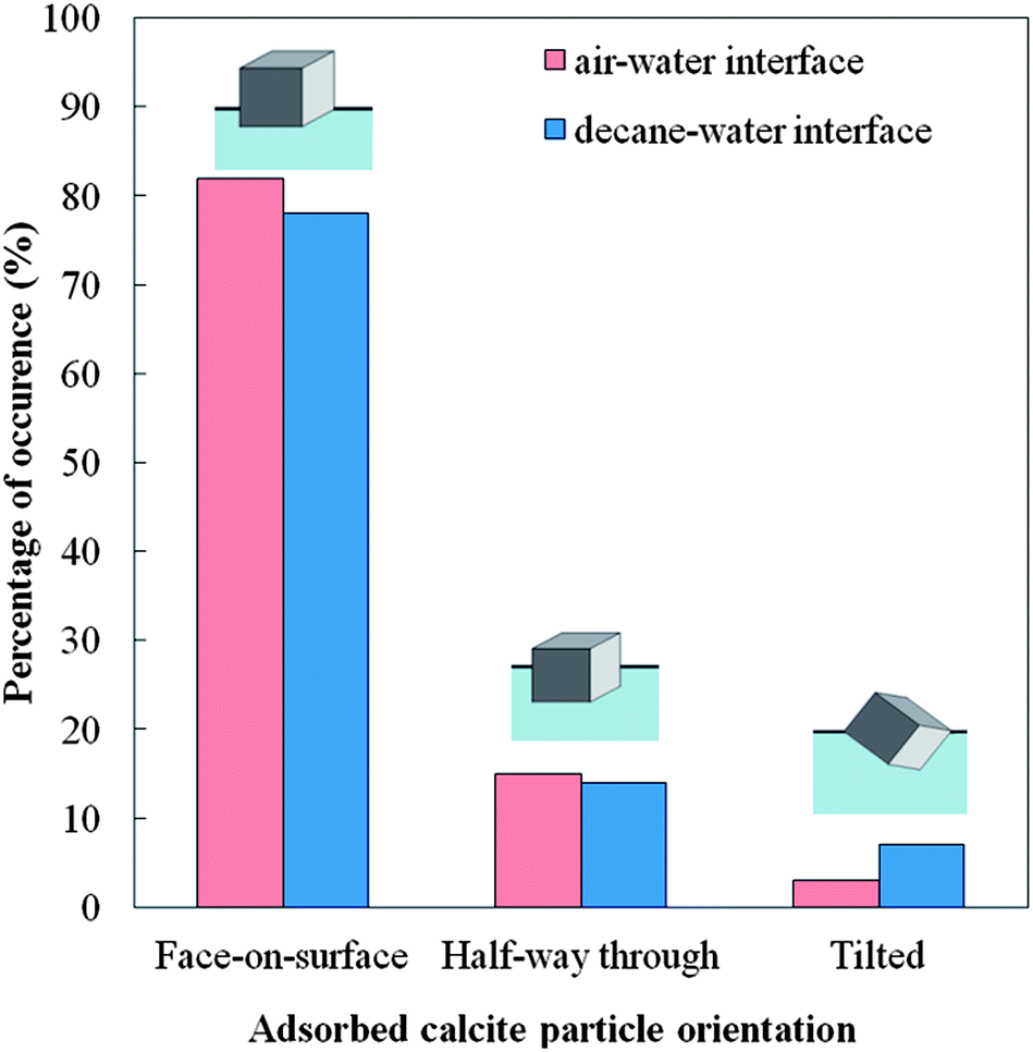 | ||
| Fig. 4 Percentage of occurrence of the particle surface orientation for three most typical configurations of adsorbed calcite microcrystals at the air–water and the decane–water interface. | ||
The second most typical configuration can be seen in Fig. 3c accounting for just about 14–15%. The rest of the calcite particles are in tilted configurations. The clustering of the particles and the small frequency of occurrence of this configuration did not allow us to determine the distribution of the tilting angle of the adsorbed calcite particles.
Ethyl cellulose micro-fibres
The layer of ethyl cellulose fibres spread at the air–water interface was successfully replicated with PDMS using the gel trapping technique. There is a large population of fibres present which seem to aggregate. It is clear from the SEM images that the fibres are fairly polydisperse in terms of length and diameter. Fig. 5a shows a large number of fibres on the surface of the PDMS. It can be seen that although the majority of the length of the fibres is in the water phase, the ends tend to be sticking into the oil phase (represented in the replica by the PDMS). One sees that the fibres have been predominantly in the aqueous phase (see the exposed part of the fibres surface at the PDMS replica). This indicates that the contact angle of the ethyl-cellulose fibres at the air–water interface is smaller than 90°, although we cannot determine it quantitatively from the images. Fig. 5b and c shows a close-up of some of the fibres. It can be seen that the fibres are quite textured (rough). This could explain their behaviour since the surface roughness affects the wettability of a material, as mentioned in the introduction. According to Wenzel's model for wetting of rough surfaces,43,44 if the smooth surface is hydrophilic, its rough surface equivalent is even more hydrophilic. We observed that the ends of the ethyl-cellulose fibres on the SEM images are much smoother than the fibre surface along its length. This observation seems consistent with the fact that the fibre ends are less hydrophilic than the rest of the fibre surface due to its roughness. The number of ethyl cellulose fibres present at the oil–water interface is vastly reduced, compared to the air–water interface. Like in the crystal case, there seems to be less aggregation. | ||
| Fig. 5 (a–c) SEM images of ethyl cellulose micro-fibres adsorbed at the air–water interface followed by its replication with PDMS by using the GTT. The parts of the micro-fibres immersed in the PDMS have been exposed to the air phase when adsorbed at the air–water interface. (d–f) SEM images of aragonite microcrystals adsorbed at the decane–water interface followed by its replication with PDMS by using the GTT. The parts of the aragonite microcrystals immersed in the PDMS have been originally immersed in the decane phase when adsorbed at the decane–water interface. The exposed surface of the micro-fibres has been originally immersed in the aqueous phase. | ||
The fibres that are at the interface seem to be twisted and have loops in them (Fig. 5d), in contrast to the air–water interface, where the fibres tend to be straight and untwisted. We also observed that the ethyl-cellulose fibres are slightly less exposed to the aqueous phase when adsorbed at the decane–water interface. This intermediate hydrophobicity at both the air–water and oil–water interface is consistent with their ability to stabilise well both foams and emulsions.45
Hydrophilic porous silica microparticles
The VP Aeroperl® 300/30 particles spread and adsorbed at the air–water interface were successfully moulded in with PDMS using the gel trapping technique. Fig. 6 shows the surface of the PDMS replica. The particles appear to be sitting within the surface, and there is a large size distribution present. The particles are behaving as anticipated. They are hydrophilic, hence expected to be exposed preferentially to the water phase, when adsorbed at the liquid surface, which is demonstrated in Fig. 6a. The hydrophilic porous silica particles spread at the decane–water interface were successfully moulded in the PDMS using the gel trapping technique as well. Fig. 6b shows the surface of the PDMS. Note that the average size of the particles present at the liquid interface is much smaller than the average size of the original polydisperse particle sample (see Fig. 2b); on the liquid surface the adsorbed particles are all smaller than 2 μm. It is also interesting to note the fact that there is no agglomeration of the particles at this interface. This could be due to repulsion of the particles from each other45 at the original oil–water interface. We observed that at the air–water system, much larger particles were present. It seems that only a fraction of smaller porous particles got successfully spread and adsorbed at the decane–water interface with IPA as a spreading solvent. The reasons for this result are unclear at present. From the SEM images we estimated the contact angles of these hydrophilic particles as 25° ± 5° when adsorbed at the air–water interface and 27° ± 4° at the decane water interface, respectively. | ||
| Fig. 6 SEM images of hydrophilic porous silica particles (VP Aeroperl® 300/30) adsorbed at the air–water interface (a–c) and the decane–water interface (d–f) followed by the surface replication with PDMS by using the GTT. The samples are imaged at a viewing angle of 65° between the electron beam and the detector. The exposed part of the particle surface has been exposed to the aqueous phase when adsorbed at the air–water surface (a–c) and the decane–water interface (d–f). | ||
Hydrophobic porous silica microparticles
We were not successful in spreading and moulding of VP Aeroperl® R806/30 (hydrophobic) porous particles at the air–water interface. The hydrophobic porous silica particles spread at the oil–water interface were successfully moulded in the PDMS using the gel trapping technique as seen in Fig. 7. As expected, the particles were predominantly exposed to the decane phase (replaced by the PDMS in the replica) and it appears that there is a variety of particle sizes present. The SEM images indicate that the contact angle of the porous hydrophobic silica was well over 90° at the decane–water interface. We estimated the approximate value of the contact angle of these porous hydrophobic particles at the decane–water interface by extrapolating the particle profile with a circle a large portion of the particle surface is embedded in the PDMS replica. This estimate gave average values of the particle contact angle of 149° ± 4°. | ||
| Fig. 7 SEM images of hydrophobic porous silica particles (VP Aeroperl® R806/30) adsorbed at the decane–water interface followed by the liquid surface replication with PDMS by using the GTT. The samples are imaged at a viewing angle of 65° between the electron beam and the detector. The exposed parts of the particle surface have been immersed in the aqueous phase when adsorbed the decane–water interface (a) and (b) correspond to different resolution. | ||
Conclusions
We applied the gel trapping technique to explore how several different types of shape-anisotropic particles, as well as porous silica microparticles adsorb and orientate at the air–water and the oil–water interface. This approach uses a hydrogel solution as the water phase which after setting “arrests” the position of the adsorbed particles at the liquid interface. It is then moulded using PDMS and viewed using high resolution scanning electron microscopy. The anisotropic particles included calcite (rhombohedra-like microcrystals) and aragonite (needle-like microcrystals), both polymorphic forms of calcium carbonate. We also looked at the adsorption of ethyl cellulose microfibers of much larger aspect ratios at both liquid interfaces. Although no particle contact angles were determined due to the complex shapes of the anisotropic particles, some general trends on their attachment and orientation at the liquid interfaces were found The rhombohedra-like calcite microcrystals when attached (by spreading with IPA) at the air–water interface tended to have a face of the crystal in the plane of the interface, with almost the entire crystal in the water phase. We did not observe any fixed angle intermediate orientation of the calcite microcrystals at the interface, which indicates that the microcrystals may be trapped in non-equilibrium positions due to contact angle hysteresis. The aragonite needle-like crystals were successfully moulded with PDMS at both the air–water and the decane–water interface. At both interfaces these microcrystals seem to preferentially lie in the plane of the interface. However, significant reorientation of the aragonite microcrystals to upright position was observed when they were spread at a high concentration at the air–water interface. Ethyl cellulose fibres were successfully moulded with PDMS and at both the air–water and the decane–water interface. The ethyl cellulose microfibers tend to aggregate at the liquid interface and in both cases the ends of the microfibres seemed to prefer to be in the non-aqueous phase (air or oil) which was attributed to surface roughness differences. The porous silica microparticles, both hydrophilic and hydrophobic, were also investigated at the air–water and decane–water interface. The porous hydrophilic silica particles were positioned almost entirely in the aqueous phase when adsorbed at the both air–water and oil–water interfaces, although the size of the particles attached at the oil–water interface was much smaller (∼2 μm) than the average particle size of the original polydisperse sample (∼30 μm). The hydrophobic porous silica particles were positioned almost entirely in the oil phase. We were not successful in spreading and moulding porous hydrophobic silica particles at the air–water interface. For each particle type, there were more particles/fibres attached at the air–water interface than the oil water interface, except for the hydrophobic porous silica particles. In conclusion, the gel trapping technique has been applied successfully to anisotropic and porous particles to study their adsorption and orientation behaviour at liquid surfaces. The results can prove very informative about the structuring of anisotropic particles at liquid surfaces in various industrial products and formulations containing anisotropic particles as stabilisers of foams and emulsions.Acknowledgements
This project was supported by Unilever, Vlaardingen, The Netherlands. H. A. thanks the Ministry of Higher Education of the Kingdom of Saudi Arabia for the funding of his PhD studentship.Notes and references
- V. N. Paunov, O. J. Cayre, P. F. Noble, S. D. Stoyanov, K. P. Velikov and M. Golding, J. Colloid Interface Sci., 1993, 156, 279 CrossRef.
- V. Klanga, C. Valentaa and N. B. Matsko, Micron, 2013, 44, 45 CrossRef PubMed.
- B. P. Binks, A. N. Boa, M. A. Kibble, G. Mackenzie and A. Rocher, Soft Matter, 2011, 7, 401 Search PubMed.
- E. Dickinson, Curr. Opin. Colloid Interface Sci., 2010, 15, 40 CrossRef CAS PubMed.
- I. Kalashnikova, H. Bizot, B. Cathala and I. Capron, Langmuir, 2011, 27, 7471 CrossRef CAS PubMed.
- G. Gillies, K. Buscher, M. Preuss, M. Kappl, H.-J. Butt and K. Graf, J. Phys.: Condens. Matter, 2005, 17, S445 CrossRef CAS.
- Z. Li, R. F. Giese, C. J. van Oss, J. Yvon and J. Cases, J. Colloid Interface Sci., 1993, 156, 279 CrossRef CAS.
- T. V. Subrahmanyam, M. B. M. Monte, A. Middea, E. Valdiviezo and F. F. Lins, Miner. Eng., 1999, 12, 1347 CrossRef CAS.
- C. Journay and P. Chassin, Colloids Surf., 1987, 27, 289 CrossRef.
- S. Ecke, M. Preuss and H.-J. Butt, J. Adhes. Sci. Technol., 1999, 13, 1181 CrossRef CAS PubMed.
- J. H. Clint and S. E. Taylor, Colloids Surf., 1992, 65, 61 CrossRef CAS.
- G. Gillies, K. Büscher, M. Preuss, M. Kappl, H.-J. Butt and K. Graf, J. Phys.: Condens. Matter, 2005, 17, S445 CrossRef CAS.
- A. Hadjiiski, R. Dimova, N. D. Denkov, I. B. Ivanov and R. Borwankar, Langmuir, 1996, 12, 6665 CrossRef CAS.
- A. Hadjiiski, S. Tcholakova, I. B. Ivanov, T. D. Gurkov and E. F. Leonard, Langmuir, 2002, 18, 127 CrossRef CAS.
- V. N. Paunov, Langmuir, 2003, 19, 7970 CrossRef CAS.
- V. N. Paunov and O. J. Cayre, Nanostructured and Advanced Materials for Applications in Sensor, Optoelectronic and Photovoltaic Technology, NATO Science Series II: Mathematics, Physics and Chemistry, vol. 204, 2005, pp. 363–366 Search PubMed.
- P. F. Noble, O. J. Cayre, R. G. Alargova, O. D. Velev and V. N. Paunov, J. Am. Chem. Soc., 2004, 126, 8092 CrossRef CAS PubMed.
- R. Aveyard, B. P. Binks and J. H. Clint, Adv. Colloid Interface Sci., 2003, 503, 100 Search PubMed.
- J. T. Davies and E. K. Rideal, Interfacial phenomena, Academic Press, New York, 2nd edn, 1963 Search PubMed.
- A. W. Adamson, Physical Chemistry of Surfaces, John Wiley and Sons, New York, 5th edn, 1990 Search PubMed.
- E. Chibovsky and L. Holisz, Langmuir, 1992, 8, 710 CrossRef.
- E. W. Washburn, Phys. Rev., 1921, 17, 273 CrossRef.
- T. S. Horozov, D. A. Braz, P. D. I. Fletcher, B. P. Binks and J. H. Clint, Langmuir, 2008, 24, 1678 CrossRef CAS PubMed.
- A. R. Morgan, N. Ballard, L. A. Rochford, G. Nurumbetov, T. S. Skelhon and S. A. F. Bon, Soft Matter, 2013, 9, 487 RSC.
- L. Yao, L. Botto, M. Cavallaro, B. J. Bleier, V. Garbin and K. J. Stebe, Soft Matter, 2013, 9, 779 RSC.
- B. J. Park, C.-H. Choi, S.-M. Kang, K. E. Tettey, C.-S. Lee and D. Lee, Soft Matter, 2013, 9, 3383 RSC.
- B. J. Park, C.-H. Choi, S.-M. Kang, K. E. Tettey, C.-S. Lee and D. Lee, Langmuir, 2013, 29, 1841 CrossRef CAS PubMed.
- E. P. Lewandowski, M. Cavallaro, L. Botto, J. C. Bernate, V. Garbin and K. J. Stebe, Langmuir, 2010, 26, 15142 CrossRef CAS PubMed.
- O. J. Cayre and V. N. Paunov, Langmuir, 2004, 20, 9594 CrossRef CAS PubMed.
- L. Isa, F. Lucas, R. Wepf and E. Reimhult, Nat. Commun., 2011, 2, 438 CrossRef PubMed.
- L. N. Arnaudov, O. J. Cayre, M. A. Cohen-Stuart, S. D. Stoyanov and V. N. Paunov, Phys. Chem. Chem. Phys., 2010, 12, 328 RSC.
- V. N. Paunov and O. J. Cayre, Adv. Mater., 2004, 16, 788 CrossRef CAS.
- Z. Lu and M. Zhou, J. Colloid Interface Sci., 2011, 361, 429 CrossRef CAS PubMed.
- B. Madivala, J. Fransaer and J. Vermant, Langmuir, 2009, 25, 2718 CrossRef CAS PubMed.
- K. M. Reed, J. Borovicka, T. S. Horozov, V. N. Paunov, K. L. Thompson, A. Walsh and S. P. Armes, Langmuir, 2012, 28, 7291 CrossRef CAS PubMed.
- W. Gibson and G. R. Sanderson, Gellan Gum, in Thickening and Gelling Agents for Food, ed. A. Imeson, Aspen Publishers Inc., U.S., 1997 Search PubMed.
- P. E. Jansson, B. Lindberg and P. A. Sandford, Carbohydr. Res., 1983, 124, 135 CrossRef CAS.
- K. Nakajima, T. Ikehara and T. Nishi, Carbohydr. Polym., 1996, 30, 77 CrossRef CAS.
- L. Wang, I. Sondi and E. Matijevič, J. Colloid Interface Sci., 1999, 218, 545 CrossRef CAS PubMed.
- E. Chibowski, L. Holysz and A. Szczes, Water Res., 2003, 37, 4685 CrossRef CAS PubMed; T. Ogino, T. Suzuki and K. Sawsada, Geochim. Cosmochim. Acta, 1987, 51, 2757 CrossRef.
- A. L. Campbell, B. L. Holt, S. D. Stoyanov and V. N. Paunov, J. Mater. Chem., 2008, 18, 4074 RSC.
- V. N. Paunov, P. A. Kralchevsky, N. D. Denkov and K. Nagayama, J. Colloid Interface Sci., 1993, 157, 100 CrossRef CAS.
- R. N. Wenzel, Ind. Eng. Chem., 1936, 28, 988 CrossRef CAS.
- H. Y. Erbil, Surface Chemistry of Solid and Liquid Interfaces, Blackwell Publishing, Oxford, 2006 Search PubMed.
- R. G. Alargova, V. N. Paunov and O. D. Velev, Langmuir, 2006, 22, 765 CrossRef CAS PubMed; H. A. Wege, S. Kim, V. N. Paunov, Q. Zhong and O. D. Velev, Langmuir, 2008, 24, 9245 CrossRef PubMed; A. L. Campbell, S. D. Stoyanov and V. N. Paunov, Soft Matter, 2009, 5, 1019 RSC.
| This journal is © The Royal Society of Chemistry 2014 |