Liquid phase stepwise growth of surface mounted metal–organic frameworks for exploratory research and development of applications
Min
Tu
,
Suttipong
Wannapaiboon
and
Roland A.
Fischer
*
Chair of Inorganic Chemistry II–Organometallics and Materials Chemistry, Ruhr University Bochum, D-44780 Bochum, Germany. E-mail: roland.fischer@rub.de
First published on 29th May 2014
Abstract
Due to their various interesting properties (e.g., porosity, chirality, magnetism and luminescence), metal–organic frameworks (MOFs) show great potential in a large number of applications ranging from life sciences to industry. One way to process and formulate them into application-specific configurations is to fabricate composite materials where MOFs are mounted on flat substrates or other shaped bodies. Among the library of MOF film preparation techniques, the liquid phase stepwise growth approach has shown its feasibility in the fabrication of homogeneous and highly crystalline surface-mounted MOFs. This review will focus on the fundamental properties (e.g., growth mechanism, sorption, electrical and mechanical properties) of stepwise grown MOF films toward the development of their applications in separation, chemical sensing and catalysis.
 Min Tu | Min Tu (born 1987, China) received his bachelor's degree in chemical engineering from China University of Mining Technology (Beijing) in 2008. Subsequently, he went to the group of Prof. Xiongfu Zhang at Dalian University of Technology to do his master thesis and obtained his master's degree in chemical engineering in 2011. Currently, he is doing his PhD thesis under the supervision of Prof. Roland A. Fischer at Ruhr University Bochum with the support of the China Scholarship Council (CSC). His research interests focus on the development of MOF thin film devices for chemical detection and separation. |
 Suttipong Wannapaiboon | Suttipong Wannapaiboon (born 1987) studied chemistry at Chiang Mai University (Thailand) and achieved his B.Sc. degree with first-class honours in 2009. After graduation, he was granted a Royal Thai Government Scholarship to study aboard and subsequently attended the Master program at Ruhr University Bochum in 2011. He did his master thesis under the supervision of Prof. Roland A. Fischer on the stepwise liquid phase epitaxial growth of MOF thin films and earned his M.Sc. in Chemistry in September 2013. Continuing to work in the same group, he is currently a doctoral student. His research interests are mainly focused on stepwise growth of MOF thin films. |
 Roland A. Fischer | Roland A. Fischer studied chemistry at Technische Universität München (TUM) and received his Dr. rer. nat. in 1989 under the guidance of Wolfgang A. Herrmann. After a postdoctoral collaboration with Herb D. Kaesz at the University of California, Los Angeles (UCLA), he returned to TUM in 1990, where he obtained his Habilitation in 1995. In 1996 he was appointed Associate Professor at Ruprecht-Karls Universität Heidelberg. In 1998 he moved to Ruhr-Universität Bochum where he took the chair in Inorganic Chemistry II. He was the Dean of the Ruhr University Research School (2006–2009). His research interests focus on group 13/transition metal compounds, precursor chemistry for inorganic materials, chemical vapour deposition (CVD), thin films, nanoparticles, colloids and in particular the supramolecular chemistry and property tailoring of porous coordination network compounds (MOFs). |
1 Introduction
Infinite networks with potential porosity built from metal (or inorganic clusters) centers bridged by organic linkers through coordination bonds are called metal–organic frameworks (MOFs),1,2 which were first developed by Yaghi and coworkers in 1995.3,4 The structural diversity and presence of both inorganic and organic components in MOFs enable a variety of interesting properties, such as high porosity,5,6 chirality,7 magnetism,8 luminescence,9 spin-crossover10,11 and electron/proton conductivity.12–14 For example, the Brunauer–Emmett–Teller (BET) surface area of MOFs can reach as high as ∼7000 m2 g−1, the highest value among all porous materials to date.6 These properties make them excellent candidate materials for a large number of applications ranging from life sciences to industry applications.7,15–25 Most studies on developing new MOF materials26–28 and functionalizing29,30 them for desired applications have mainly focused on bulk powder materials. However, other practical applications of MOFs, such as membrane-based separation,31,32 optical and electronic devices,33 chemical sensors16,34,35 and electrodes,14,36,37 require them to be fabricated on given substrates. For example, the use of MOFs for chemical sensing requires a uniform-layer deposition of MOFs on special devices that provide signal conduction and transformation, such as a quartz crystal microbalance (QCM) and a surface acoustic wave (SAW). Thus, the development of fabrication techniques for integrating MOFs into such specific substrates and devices becomes an important issue. Recently, a number of techniques, including in situ,38–41 secondary growth,42–44ex situ45 and liquid phase stepwise growth methods46–60 (also called layer-by-layer (LbL) or sequential growth), have been developed to fabricate MOF films on various substrates for practical applications. Among them, liquid phase stepwise growth is a promising method for MOF film fabrication. Initiated from an alternating adsorption of electrostatic-charged polymers or colloids on substrates,61,62 the term “stepwise growth” is currently widely used to describe various film growth processes by stepwise bottom-up protocols. The general idea of the stepwise growth technique is that the components of reactants are sequentially dosed onto the surfaces. Unreacted or weakly physisorbed components are removed between successive deposition steps by rinsing with an appropriate solvent. In comparison with other techniques for MOF film fabrication, the stepwise growth method offers several advantages: (1) a homogeneous and smooth film for which the root mean square (rms) roughness can be as low as 2 nm;48,59 (2) controllable thickness, obtained by varying the number of deposition cycles;48,51,59 (3) easy scale-up; (4) perfectly oriented films, achieved by altering the surface functional groups;46,47,54,57 and (5) lower defect density than the bulk material synthesized by conventional methods.63 A number of lab-scale applications have been developed, including separation,64–72 chemical sensing73–79 and catalysis,80–82 by utilizing this advanced technique of coupling MOFs. In addition, this technique can be used for fundamental studies that are critical for realistic applications. As shown in Fig. 1, we pay particular attention in this review to MOF films fabricated by the stepwise liquid phase growth approach, which is exploited for fundamental studies (growth mechanism, conductivity, porosity, light harvesting, mechanics and optics) toward realistic applications (separation, chemical sensing and catalysis). The aim is to bridge the gap between fundamental studies of stepwise grown MOF films and realistic applications by highlighting the recent advances and encouraging further research in this important field. The fabrication details of this technique, including the experimental parameters and characterization, are beyond the scope of this review. Readers are encouraged to see the recently published excellent reviews (ref. 34, 83–85) regarding these issues. We emphasize not only MOFs grown on flat substrates but also MOFs grown on preformed nano/microparticles, yielding functional composites that can confer additional properties such as magnetism,86,87 luminescence,79,88 and catalysis89,90 to facilitate other novel applications.91,92 The MOFs fabricated on various substrates for the fundamental studies and applications emphasized in this review are summarized in Table 1. | ||
| Fig. 1 Schematic representation of liquid phase stepwise growth of surface-mounted metal–organic frameworks (MOFs) for fundamental studies and the development of realistic applications. | ||
| MOF formula | Substrate | Properties or applications | Ref. |
|---|---|---|---|
| SAM = self-assembly monolayer; btc = benzene-1,3,5-tricarboxylate; dmcapz = 3,5-dimethyl-4-carboxypyrazolato; (+)cam = (1R,3S)-(+)-camphoric acid; (−)cam = (1S,3R)-(−)-camphoric acid)); dabco = 1,4-diazabicyclo(2.2.2)octane; ndc = 1,4-naphthalene dicarboxylate; bdc = 1,4-benzene dicarboxylate; NH2-bdc = 2-amino-1,4-benzene dicarboxylate; BME-bdc = 2,5-bis(2-methoxyethoxy)-1,4-benzene dicarboxylate; mim = 2-methyl imidazole; dobdc = 2,5-dioxido-1,4-benzene dicarboxylate; 4-bpdh = 2,5-bis(4-pyridyl)-3,4-diaza-2,4-hexadiene; 4-bpdh = 2,5-bis(4-pyridyl)-3,4-diaza-2,4-hexadiene. | |||
| [Cu3(btc)2](HKUST-1) or loaded with guest molecules | –COOH and –OH SAM on Au, | Growth mechanism study | 93 |
| Al2O3, SiO2, –COOH and –OH SAM on Au | Growth mechanism study | 94 | |
| –COOH SAM on Au | Sorption | 95 | |
| SiO2 with patterned Pt pads on Si wafer | Electrical conductivity | 36 | |
| FTO-coated glass with thin TiO2 layer | Electrical conductivity | 96 | |
| –COOH SAM on Au | Electrical conductivity | 97 | |
| –COOH SAM on Au | Light harvesting | 98 | |
| –COOH SAM on Au | Mechanical properties | 99 | |
| Si wafer | Optical properties | 100 | |
| Porous Al2O3 disc | Membrane-based separation | 65 | |
| Fused silica capillary | Chromatographic separation | 68 | |
| Microcantilever chip | Sensor | 73 | |
| Quartz surface acoustic wave | Sensor | 77 | |
| Silica colloidal crystals | Sensor | 75 | |
| Monodispersed polystyrene | Sensor | 76 | |
| Silver nanoparticle array | Sensor | 74 | |
| Zn4O(dmcapz)3 and its derivatives | –OH SAM on Au coated QCM substrate | Sorption | 101 |
| [Zn2((+)cam)2(dabco)] and [Zn2((−)cam)2(dabco)] | –COOH and pyridine SAM on Au coated QCM substrate | Sorption | 102 |
| [Cu2(ndc)2(dabco)] | –COOH and pyridine SAM on Au coated QCM substrates | Sorption | 103 |
| Pyridine SAM on Au coated QCM substrates | Sorption | 104 | |
| Heterostructured [Cu2(L)2(dabco)], L = bdc, ndc and NH2-bdc | Pyridine SAM on Au coated QCM substrate | Sorption | 105,106 |
| Heterostructured [Cu3(btc)2] on [Cu2(ndc)2(dabco)] | Pyridine SAM on Au coated QCM substrate | Sorption | 107 |
| ([5,15-Bis-[4-(pyridyl)ethynyl]-10,20-diphenylporphinato]zinc(II)) (DA-MOF) and ([4,4′-bipyridine-5,10,15,20-tetrakis(4-carboxyphenyl)porphyrin]zinc(II)) (L2-MOF) | Amine-terminated Si and ITO | Light harvesting, sorption | 142 |
| [Cu2(BME-bdc)2(dabco)] and [Cu2(ndc)2(dabco)] | Porous TiO2 and α-Al2O3 disc | Membrane-based separation | 66 |
| [Zn(mim)2](ZIF-8) | Porous Al2O3 disc | Membrane-based separation | 108 |
| [Ni2(dobdc)](Ni-MOF-74) | Porous α-Al2O3 disc | Membrane-based separation | 67 |
| [Zn4O(bdc)](MOF-5) | Fused silica capillary | Chromatographic separation | 64 |
| [Cu2(bdc)2(dabco)] | Fused silica capillary | Chromatographic separation | 69 |
| [Fe3O(btc)2](MIL-100(Fe)) | –COOH-terminated Fe3O4 nanoparticles | Magnetic solid state extraction and catalysis | 70,81,82 |
| –COOH-terminated Au nanoparticles | Catalysis | 80 | |
| [Pb(4-bpdh)(NO3)(H2O)](HMTI-1) | Silk fiber | Recovery of toxicant | 71 |
| [Tb(btc)](MOF-76) | –COOH-terminated Fe3O4 nanoparticles | Sensor | 79 |
2 Understanding of MOF growth on surfaces
Numerous studies have been conducted that provide ways to develop new structures or mix component MOFs. However, the implementation of MOFs in practical applications, particularly in MOF films, requires not only the development of new materials but also control of their crystal properties, such as crystallinity, morphology, thickness and orientation. Such control will aid in the development of a variety of functional MOF devices, which will critically affect their performance in realistic applications and further enable their use in other novel applications. Hence, obtaining insight into how MOF crystals have been grown may facilitate this type of control and consequently the development of new and/or more advanced applications for this fascinating group of materials. To understand the growth mechanism of MOFs, several techniques have been applied, such as atomic force microscopy (AFM),109,110 electrospray ionization mass spectrometry (ESI),111 and extended X-ray absorption fine structure spectroscopy (EXAFS).112 As MOFs are obtained from a mixture containing a variety of species, reactants and intermediates, such as secondary building units (SBUs), it is rather difficult to study the role of each reaction component in the film growth with the aforementioned techniques. In comparison with the conventional hydro/solvothermal growth, the liquid phase stepwise growth approach offers a convenient way to investigate the effect of different metal precursors on MOF growth. Shekhah et al.93 used surface plasmon resonance (SPR) to investigate the nucleation and growth mechanism of [Cu3btc2] on various surfaces by employing stepwise growth methods with different types of copper sources. The results showed that no deposition of [Cu3btc2] was observed when using copper nitrate as a precursor. However, using copper acetate as the copper source led to the successful deposition of [Cu3btc2] on –COOH and –OH terminated surfaces. According to the SPR signal and XRD patterns, the authors proposed that [Cu3btc2] was formed by stepwise ligand exchange reactions between attached surface groups and preformed SBUs (Cu2+ dimer [Cu2(CH3COO)4(H2O)2]), which is the dominant unit in the copper acetate solution. Thus, the formation of SBUs has been proposed to be critical for the assembly of MOFs on surfaces by a stepwise deposition approach. Considering the importance of SBUs in the fabrication of MOF thin films by the stepwise deposition approach, several MOF thin films (e.g., [Zn4O(bdc)3],64,113 [Zn4O(dmcapz)3]101,114 and [M2L2P] type MOF49,59,102,103,105,106,115 (M = Zn, Cu; L = dicarboxylate linkers; P = diamine pillars)) were fabricated on various surfaces using preformed SBUs as metal sources.Although the stepwise growth strategy requires only simple procedures, its growth mechanism is still not fully understood. Later on, Stavila et al.94 systematically investigated the growth of [Cu3btc2] on various surfaces (SiO2, Al2O3, –OH and –COOH SAM). In situ monitoring of [Cu3btc2] growth using QCM and QCM-D techniques provides data to establish the kinetics of film growth and allows the calculation of the reaction rates and transition-state thermodynamics. The [Cu3btc2] growth rate depends on the composition of the surface, with the growth rate on different surfaces decreasing in the following order: Al2O3 > SiO2 > –OH SAM > –COOH SAM. According to the temperature-dependent kinetics data, the activation energy of [Cu3(btc)2] thin film deposition is approximately an order of magnitude lower than the value of bulk formation. Based on this investigation, the authors proposed a comprehensive mechanism for the stepwise growth of [Cu3(btc)2] on surfaces, which involves the following 4 steps: (1) nucleation, in which Cu(II) species (the paddlewheel units) rapidly adsorb onto the surface (k0); (2) ligand exchange between coordinated acetate and H3btc (k1); (3) copper acetate addition (k2), resulting in [Cu3(btc)2] structure formation; and (4) continuous film deposition via k1 and k2 to generate a continuous dense film. This state of the art [Cu3(btc)2] thin film growth kinetics by liquid phase stepwise deposition is also called a “self-terminated layer-by-layer growth mechanism”. The adsorptions of the dosing agents generally reach the saturated level in each individual step during the fabrication. As shown in Fig. 2, using the example of a hydroxylated silica surface, during the nucleation step (rate k0), the surface OH groups react with copper acetate species in solution and consequently form the initial surface precursor for [Cu3(btc)2] growth. The very early stages of adsorption most likely involve disordered copper paddlewheel units randomly oriented on the surface. As the surface becomes saturated with Cu(II) species, it is possible that they prefer a more uniform packing and become more oriented on the surface. Subsequent exposure to a solution of the H3btc linker results in ligand exchange at the rate k1 and possibly the further reorientation of the surface paddlewheel units to accommodate the bridging H3btc ligands. Afterwards, during the next exposure to copper acetate (occurring at rate k2), the bridging btc ligands are replaced to create SBUs with a molar ratio between btc and Cu of 2![[thin space (1/6-em)]](https://www.rsc.org/images/entities/char_2009.gif) :3, similar to the molar ratio within the MOF structure. Finally, as the growth proceeds, sequential exposure to solutions of copper(II) acetate and H3btc results in the formation of [Cu3(btc)2] nuclei that further coalesce to generate a continuous film.
:3, similar to the molar ratio within the MOF structure. Finally, as the growth proceeds, sequential exposure to solutions of copper(II) acetate and H3btc results in the formation of [Cu3(btc)2] nuclei that further coalesce to generate a continuous film.
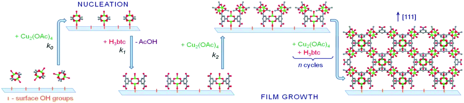 | ||
| Fig. 2 Schematic representation of the proposed growth mechanism of [Cu3(btc)2] on oxide surfaces employing liquid phase stepwise growth. The atoms are shown as follows: Cu, green; O, red; C, gray. [Reproduced from ref. 94 with permission from the Royal Society of Chemistry.] | ||
Unlike the kinetic growth behavior of the MOF films mentioned above, Wannapaiboon et al.114 recently reported a deviation from the self-terminated layer-by-layer growth mechanism observed in the stepwise epitaxial growths of [Zn4O(carboxypyrazolato)3] films coupled with the in situ monitoring of QCM frequency change. In the dosing of the zinc SBU, the mass uptake does not lead to saturation until the washing step, and the permanent chemisorptions of the zinc species onto the surface occur in this stage. In the linker dosing step, the linkers are first physisorbed onto the surface (showing a rapid increase of the dissipation value) and subsequently react with the pre-adsorbed Zn SBU species to form the desired MOF film. The excess physisorbed linkers and the substituted acetate units are further removed during the following washing step (showing a decrease in mass uptake until reaching a saturation level and the reduction of the dissipation value to nearly zero again). Based on these observations, it is proposed that the MOF nuclei are formed with an island growth mode in the early nucleation stage and consequently overgrown on all facets of the preformed crystallites in a core–shell fashion to form a highly crystalline film. However, further quantitative study is required to elucidate the growth mechanism in detail.
3 Investigation of fundamental properties
The great potential of MOFs in applications such as gas/liquid separation, chemical sensors, drug delivery, and catalysis is based on their fundamental properties, such as adsorption and desorption, conductivity, thermal and chemical stability, and mechanical and optical properties. Thus, the investigation of their fundamental properties is crucial to develop them for practical applications. Herein, the properties of stepwise grown MOF films are investigated under 5 general categories: (1) sorption, (2) electrical, (3) light harvesting, (4) mechanical and (5) optical properties.3.1 Sorption properties
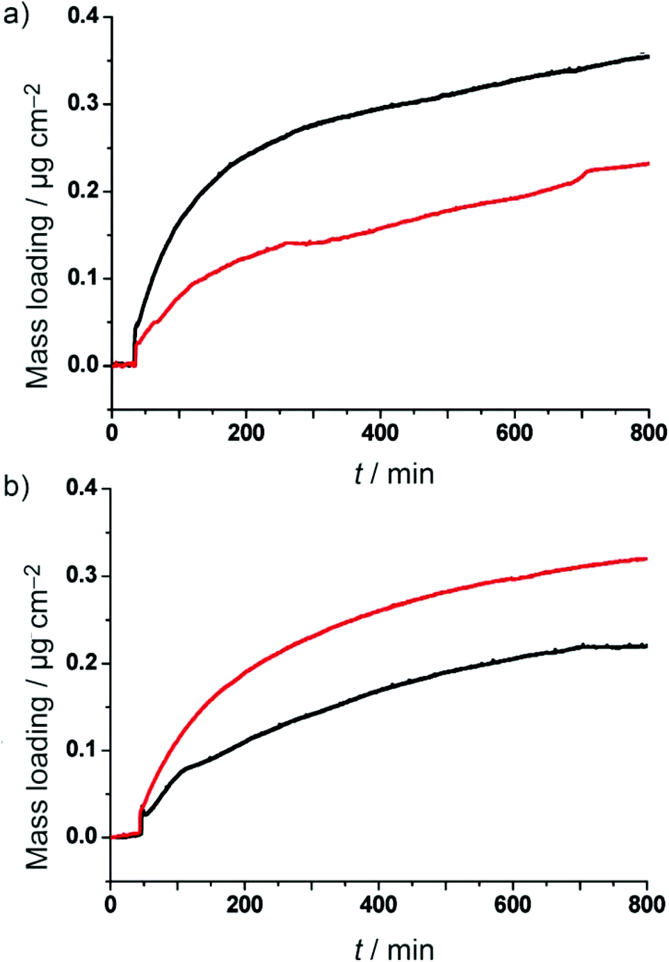
The main feature of MOFs is their uniform and high porosity, which can be used in several applications, such as separation,17,22 hydrogen storage,18 and CO2 capture.19 The investigation of the equilibrium and kinetic sorption properties of porous materials deposited on the surface is important for developing them for practical applications. For example, in the case of the membrane based separation technique, the influence of the mixed gas adsorption selectivity on the membrane selectivity can be roughly estimated using the simple relationship “membrane selectivity ≈ adsorption selectivity × diffusion selectivity”.116 However, investigating the sorption properties of MOF thin films is a challenge, as the commercial adsorption setup (gravimetric and volumetric) cannot be applied to the supported thin films. Taking advantage of the QCM technique, the frequency change of the QCM signal during the adsorption on rigid thin films could be quantitatively converted into a mass change. Therefore, an environmentally controlled QCM setup that monitors the oscillation frequency at various relative pressures of gases or vapors is well suited for the quantitative sorption monitoring and quality assessment of MOF thin films.117 Moreover, the sorption properties of MOF thin films could also be obtained by monitoring the refractive index and thickness during the sorption process of gases or volatile species, following the Kelvin equation from effective medium approximation theory (i.e., ellipsometric porosimetry, EP).118–120Due to the significant differences in the biological and pharmacological properties of the isomers of chiral compounds, much attention has been paid to the chiral resolution. Homochiral porous MOFs could serve as attractive candidates for heterogeneous asymmetric catalysts and enantioselective adsorbents and as separators for the production of optically active organic compounds.7,121,122 Therefore, investigating the adsorption and diffusion of enantiomeric molecules in MOFs is essential to promote homochiral MOFs into chiral resolution. Liu et al.102 fabricated two homochiral MOF films, [Zn2((+)cam)2(dabco)] and [Zn2((−)cam)2(dabco)], directly on SAM/Au modified QCM substrates to study the adsorption kinetics of enantiomeric guest molecules, namely, (2R,5R)-2,5-hexanediol (R-HDO) and (2S,5S)-2,5-hexanediol (S-HDO). As seen in Fig. 3, [Zn2((+)cam)2(dabco)] exhibits approximately a 1.5-fold preference for the adsorption of R-HDO over S-HDO at the equilibrium time (at 800 min of exposure), whereas [Zn2((−)cam)2(dabco)] exhibits the inverted selectivity, a 1.5-fold adsorption preference for S-HDO over R-HDO. Although the racemate separation cannot be obtained by this approach because the QCM signal cannot distinguish R- and S-HDO in the case of the adsorption of a racemic mixture, this fundamental investigation may indicate that these MOFs may be used in chiral resolution by membrane-based separation and chromatographic separation. Later, several homochiral MOF membranes were fabricated for chiral resolution in spite of using other fabrication techniques.123–125
 | ||
| Fig. 3 QCM profiles of specific mass uptake of each enantiomer from the vapor phase at saturated vapor pressure: (a) R-HDO (black) and S-HDO (red) over [Zn2((+)cam)2(dabco)] and (b) R-HDO (black) and S-HDO (red) over [Zn2((−)cam)2(dabco)]. [Reprinted with permission from ref. 102. Copyright 2011 Willy-VCH.] | ||
In addition to the importance of investigating the equilibrium sorption properties of MOFs deposited on surfaces, the kinetics of adsorption of guest molecules is also a significant issue. Due to the homogeneous nature and the defined thickness of MOF films by the stepwise growth approach, the transport diffusion constants for small molecules can be determined by analyzing the QCM data using the Fickian diffusion model. In the case of pyridine diffusion within [Cu3btc2] films at room temperature, the diffusion constant was determined to be 1.5 × 10⁻¹⁹ m2 s−1.95 The binding energy of 18 kcal mol−1 of the pyridine to the Cu2+ sites within [Cu3btc2] was determined, which is in good agreement with the results of precise ab initio quantum chemistry calculations. Similarly, Heinke et al.104 studied the diffusion of ferrocene in the thin film [Cu2(ndc)2(dabco)] using this method. The mean values of the ferrocene transport diffusivities at 305 K, 320 K and 335 K were 6 × 10⁻¹⁹ m2 s−1, 3 × 10⁻¹⁸ m2 s−1 and 2 × 10⁻¹⁷ m2 s−1, respectively. By analyzing the Arrhenius plot of the diffusivities, the activation energy for ferrocene diffusion was determined to be 90 ± 30 kJ mol−1.
It is well recognized that, for most framework structures, different film orientations could result in differences in properties such as separation and optical transparency.126–129 In particular, MOFs crystallized as anisotropic crystallographic systems should exhibit distinct adsorption kinetics for adsorbates approaching from different directions due to varied pore openings.103,130 As mentioned above, differently oriented MOF films could be obtained by alternating the functionality of SAMs on substrates employing stepwise growth. Therefore, this method is suited for studying orientation-dependent adsorption on MOF films by the coupling QCM technique. Liu et al.103 demonstrated the orientation-dependent adsorption behavior of aromatic compounds (benzene, toluene, p-xylene) for [Cu2(ndc)2(dabco)] thin films in the [100] and [001] orientations. The pore opening of [Cu2(ndc)2(dabco)] in the [100] orientation is slightly larger than that in the [001] orientation, which results in faster kinetics for benzene, toluene and p-xylene in the film with the [100] orientation. The observed adsorption rate could motivate future investigations with the goal of achieving control of the permeation rate in porous MOF membranes by adjusting orientations and morphologies.
For example, as shown in Fig. 4, Meilikhov et al.105 prepared three types of heterogeneous MOF films by stepwise hetero-epitaxial growth and post-synthetic modification. By coupling QCM technique for single and mixture sorption experiments, the directional permeability and selective adsorption behavior were examined by changing the spatial arrangement of A and C. The Type I(C@A) coatings could selectively adsorb small and polar methanol molecules over hexane molecules from their mixture; however, the inverse structure of Type II(A@C) coatings showed no selectivity. This result clearly implies that framework C located on top of Type I(C@A) blocks the transportation for hexane into the material. In the case of Type II(A@C) and Type III(AC) materials, no blocking effect could be observed due to the lack of homogeneous coating of A with C. Thus, the tunable analyte affinity depends strongly on the top surface functionality, which emphasizes the importance of the spatial separation of distinct MOF systems.
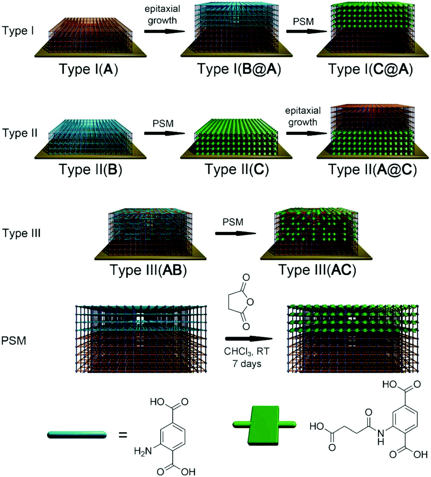 | ||
| Fig. 4 Different types of heterostructured-MOFs films with MOF A: [Cu2(ndc)2(dabco)]; B: [Cu2(NH2-bdc)2(dabco)]; C: [Cu2(HOOC(CH2)2OCNH-bdc)2(dabco)]. PSM refers to post-synthetic modification within the reaction between amino groups in film B and succinic acid anhydride. [Reprinted with permission from ref. 105. Copyright 2013 Willy-VCH.] | ||
Liu et al.106 studied the kinetics of adsorption of 4-fluorophenyl isothiocyanate (FPI) on single and hetero-MOF films (A, A–B and A–B–C: A: [Cu2(bdc)2(dabco)]; B: [Cu2(NH2-bdc)2(dabco)]; C: [Cu2(ndc)2(dabco)]), respectively. Fig. 5 shows the FPI adsorption over A, A–B and A–B–C recorded by QCM, which was semi-quantitatively analyzed. The saturated adsorption amount is approximately proportional to the total number of deposition cycles for films of A, A–B and A–B–C. The observed two-stage adsorption is attributed to the physical and chemical adsorption of FPI in the multilayers of A and B. The first adsorption stage is very close to that in film A, and the second much slower adsorption rate could be ascribed to the FPI adsorption in the top layer B due to the slightly smaller pore space and reaction process between isothiocyanate and amino groups. Three stages of adsorption were observed, which are associated with the three types of pore structures in film A–B–C. The first two stages are quite similar to the ones observed in A–B, matching the expectations deduced in the case of A–B. The third step of adsorption can be attributed to adsorption in the outer layer C. The slower diffusion rate is reasonable due to the smallest pore opening of C without an active site to react with the guest molecule. The multiplex adsorption property of the hybrid MOF films suggests that the amount and location/distribution of MOF functionalities could be precisely controlled by taking advantage of the stepwise deposition approach.
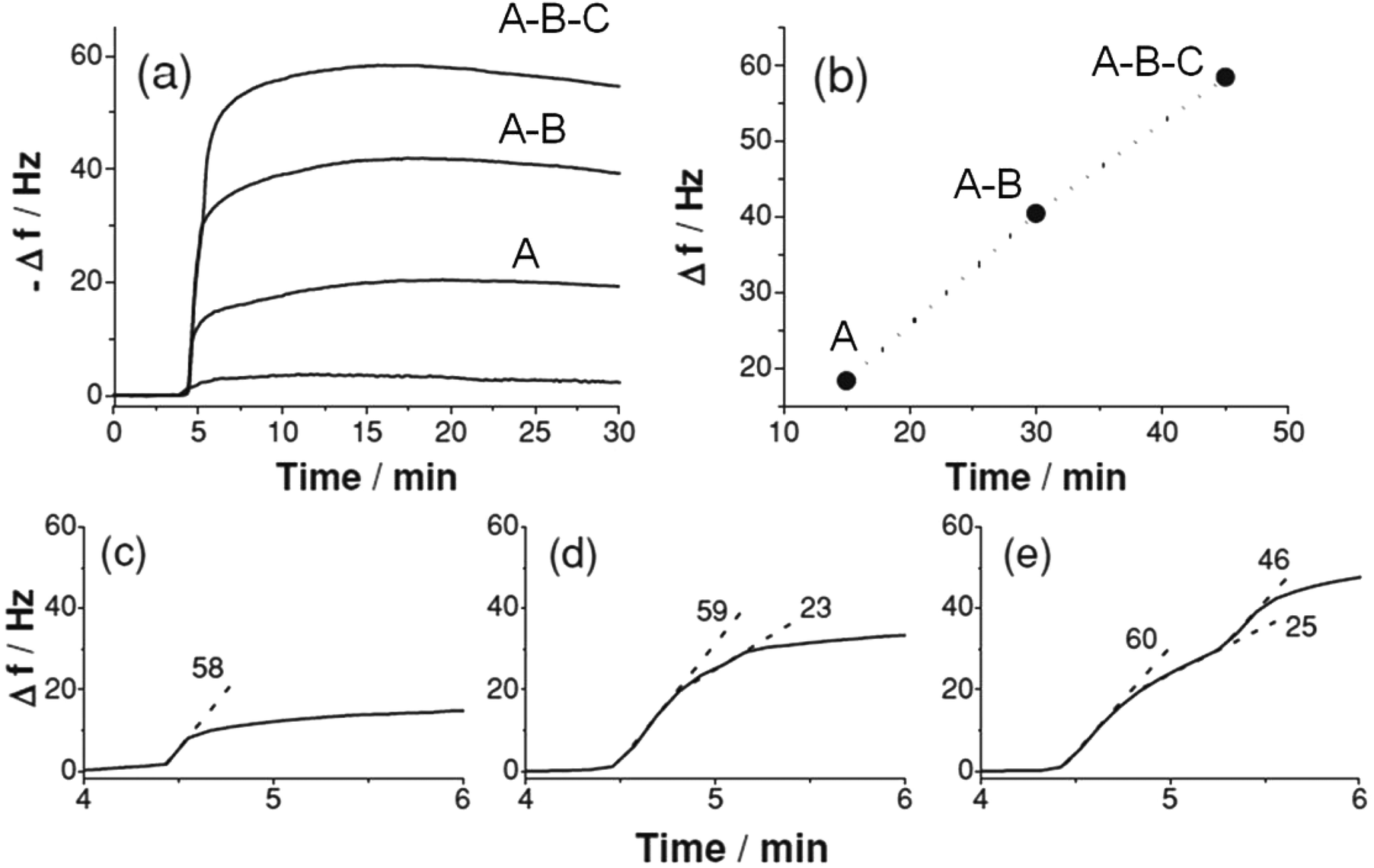 | ||
| Fig. 5 (a) In situ QCM monitoring of gas phase FPI (vapor) loading over activated MOF films A, A–B and A–B–C (15 cycles for each sub-multilayer of A, B and C) using N2 as the carrier gas at a flow rate of 5 sccm; (b) plot of FPI adsorption against the total number of sample deposition cycles and analysis of FPI adsorption kinetics (by slope, −df/dt in [Hz s−1]) on (c) A, (d) A–B and (e) A–B–C. The slope is evaluated by linear fitting of each linear part of the adsorption curve. [Reprinted with permission from ref. 106. Copyright 2013 Willy-VCH.] | ||
As we discussed above, hybrid adsorption functions of MOF films could be achieved by hetero-epitaxial growth. However, the hetero-MOF films mentioned above are all based on lattice matching, which limits the development of more functional hybrid MOF films. Fabricating hetero-MOF films from two lattice-mismatched components is a challenge. Considering the homogeneous nature of the external surface of a MOF film obtained by the stepwise deposition approach, it may be suitable for growth of one MOF film on another one, even with lattice mismatch. Very recently, Tu et al.107 deposited [Cu3(btc)2] on top of [Cu2(ndc)2(dabco)] on a pyridyl-terminated surface using the stepwise growth approach, which demonstrated the feasibility of using the stepwise growth approach for integrating two lattice-mismatched components into one film. The [001]-oriented bottom film [Cu2(ndc)2(dabco)] offers N-donors that can template the growth of [Cu3(btc)2] along the [111] direction. Hybrid adsorption properties were obtained in the case of hetero-MOF film compared to the corresponding single ones due to the two distinct pore structures in one system.
3.2 Electrical properties
By combining the long-range crystalline order of MOFs with the ability to conduct electrical charge, MOFs can be well suited for a wide variety of applications in developing new electronics, sensors as well as energy conversion and storage devices.12,14,33 However, most MOFs exhibit poor electrical conductivity due to the low electroactivity of organic linkers and the absence of efficient overlaps between the p orbitals of the organic linker and the d orbitals of the metal ions. Only a few MOFs with certain particular linkers have been reported as conductive materials.14,134 An alternative way to enhance the electrical transport properties within the framework of MOFs is by doping special molecules into the MOF pores. In addition, to investigate the electrical conductivity of MOFs, they should be deposited on electrodes for electronic transport characterization. Lee et al.96 used the stepwise deposition technique to fabricate a [Cu3(btc)2] thin film device loaded with I2 molecules. The results showed that the electrical resistance of the [Cu3(btc)2] device could be switched from an insulator to an electrically conductive material with a conductivity of 2.43 × 10⁻⁴ S m−1 by doping I2 molecules into the pores. The increased electrical conductivity is attributed to the intermolecular interactions between I2 and π-electrons from aromatic rings as well as the high intrinsic order of MOFs. Additionally, Dragässer et al.97 reported an increase in conductivity by loading [Cu3(btc)2] thin film with ferrocene molecules, which subsequently act as immobilized redox mediators. Electron conductivity was achieved by hopping transport between the adjacent loaded ferrocene molecules in the structure of [Cu3(btc)2], beginning with an oxidation reaction of the ferrocene molecules in contact with the positive electrode.Very recently, Talin et al.36 demonstrated that the electrical conductivity of a [Cu3(btc)2] film could be controllably tuned by dosing the pores with the redox-active, conjugated guest molecules 7,7,8,8-tetracyanoquinododimethane (TCNQ). First, a thin [Cu3(btc)2] film was grown on electrodes using the stepwise growth approach. As seen from Fig. 6A, the as-grown thin film device shows an insulator feature with very low conductivity (∼10−6 S m−1). After exposing the activated device, from which the coordinated water molecules within the frameworks are removed completely, to a TCNQ solution for 3 days, the conductivity increases significantly to 7 S m−1, six orders of magnitude higher than the unloaded as-grown device. Moreover, the high conductivity of the TCNQ-loaded devices remained for at least 40 days under an ambient atmosphere (Fig. 6C). This high stability suggests no desorption of TCNQ molecules from the pores under an ambient atmosphere, which is very important for developing it for realistic application. The activation energy (Ea) was determined to be 41 ± 1 meV from the Arrhenius plot of the conductivities with different temperatures (Fig. 6E). This value is similar to the values reported for high-mobility organic polymeric semiconductors.135 Importantly, as shown in Fig. 6F, the conductivity could be tuned over several orders of magnitude by changing the TCNQ exposure time. Spectroscopic data, together with ab initio calculations, suggest that the high conductivity of the TCNQ-loaded device arises from bridging the copper paddlewheel units with TCNQ molecules through the uncoordinated sites, leading to a strong electronic coupling between the dimeric Cu subunits.
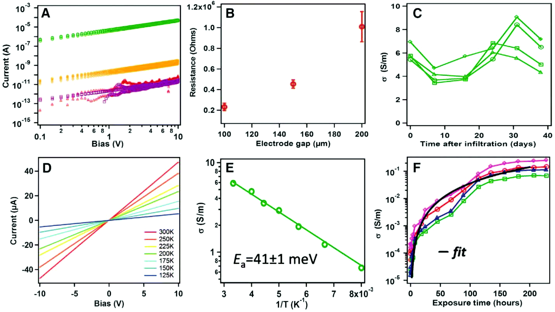 | ||
| Fig. 6 Electronic transport characteristics of [Cu3(btc)2] thin film devices. (A) I–V curves before (red) and after infiltration with TCNQ (green), F4-TCNQ (gold), or H4-TCNQ (purple). (B) Channel-length dependence of conductivity for TCNQ-infiltrated devices; error bars denote SD. (C) Stability of conductivity over time for several TCNQ-infiltrated devices. (D) Temperature dependence I–V curve. (E) Arrhenius plots of the conductivities. (F) Conductivity versus exposure time for several devices. The black line is a fit to percolation theory, σ = 4 × 10⁻⁶ (t − 0.5)2, where t is exposure time. [Reprinted with permission from ref. 36. Copyright 2014 American Association for the Advancement of Science.] | ||
3.3 Light harvesting
Scientists have long been interested in developing novel materials for harvesting and converting sunlight into electrical or chemical energy (e.g., solar cells and artificial photosynthesis) due to their green and renewable nature. A number of artificial light-harvesting antenna assemblies have been investigated, including dendrimers,136 chromophoric polymers,137 covalently linked porphyrin arrays,138 and self-assembling supramolecular systems.139 Recently, MOFs have begun to receive attention as alternative compounds for configuration as light-harvesting systems. The well-defined crystal structures of MOFs and the high degree of chromophore ordering achievable may provide a unique opportunity for systematically relating structure and composition to photon capture and energy transfer.25 A few metalloporphyrin-based MOFs showed light-harvesting and interesting photocatalytic activities.140,141 However, for the application of MOFs in a solar energy conversion device, their growth as supported films is required. Hupp and coworkers142 reported two pillar paddlewheel type MOF films, DA-MOF ([5,15-bis-[4-(pyridyl)ethynyl]-10,20-diphenylporphinato]zinc(II)) and L2-MOF ([4,4′-bipyridine-5,10,15,20-tetrakis(4-carboxyphenyl)porphyrin]zinc(II)). The relatively low temperature for stepwise growth would enable non-metalated porphyrins to be incorporated directly, whereas porphyrins in dense dropcast films exhibited significant aggregation and electronic interaction. To detect energy migration, a squaraine dye (S1) was attached on top of each investigated film as a supplementary chromophore (Fig. 7a). Fig. 7b shows that efficient migration and trapping indeed occur within the DA-MOF thin film. Fig. 7c is an excitation spectrum (monitored at S1 emission at 780 nm) illustrating that S1 emission is sensitized by DA-MOF. The peaks at 458 and 750 nm indicate the participation of P1 ([5,15-di(4-pyridylacetyl)-10,20-diphyenyl]porphyrinatozinc(II)) and S1, respectively, as light-harvesters for S1 emission. Porphyrinic sensitization of S1 is also observed with L2-MOF. Photophysical studies with porphyrinic MOF films that are terminated with a far-red emitting squaraine dye show that the films can be used as antenna for light harvesting. These investigations point to the potential application of porphyrin-based MOF films in solar energy conversion devices as an efficient light-harvesting and energy transport component.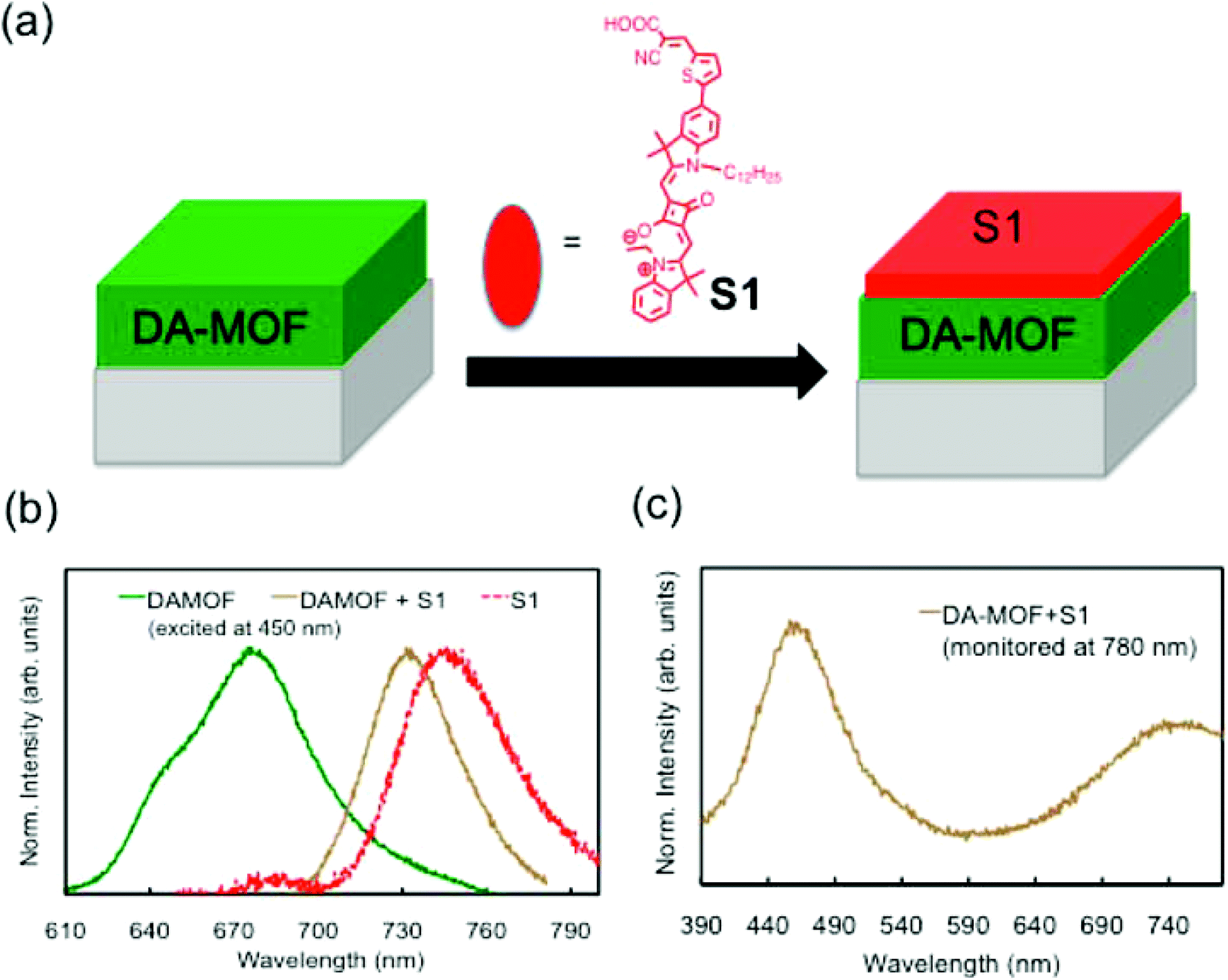 | ||
| Fig. 7 (a) Schematic illustration of the preparation of sensitized DA-MOF film. (b) Comparison of the emission profiles of DA-MOF (green solid), S1 (red solid), and DA-MOF sensitized with S1 (light green dotted) upon excitation at 450 nm. (c) Excitation profile of the DAMOF + S1 film monitored at 780 nm, where the emission from DA-MOF is negligible. [Reprinted with permission from ref. 142. Copyright 2013 American Chemistry Society.] | ||
Similar to the improvement of electrical conductivity, light-harvesting could also be achieved by incorporating functional (i.e., luminescent) molecules into porous MOFs. Streit et al.98 loaded a stepwise deposited [Cu3(btc)2] thin film with Eu β-diketonate complexes, Eu(bzac)3bipy (bzac = 1-benzoylacetone, bipy = 2,2′-bipyridine), to achieve light-harvesting. The excitation spectra of the loaded [Cu3(btc)2] thin film indicate efficient energy transfer between the [Cu3(btc)2] and the Eu3+ ion, most likely through bzac ligands, with a higher efficiency than the value observed for pure complexes. This result indicates that the [Cu3(btc)2] thin film effectively works as an antenna, efficiently converting incident radiation into electronic excitations and then transferring them to the Eu3+ ions.
3.4 Mechanical properties
Knowledge of the mechanical properties of MOFs is important for the optimal performance of the envisioned applications.143 For example, MOF film applications in flexible electronics require sufficient elasticity (low Young's modulus) to avoid the formation of cracks. However, in relation to stress-induced chemical sensing devices based on MOF structures, film stiffness (high Young's modulus) and strong adhesion between films and substrates are key mechanical properties to be addressed.Bundschuh et al.99 investigated the mechanical properties (hardness and Young's modulus) of the stepwise grown thin film [Cu3(btc)2] using standard indentation methods that allow repeated measurements several times on the same substrate. Compared with other polycrystalline MOF films with high roughness, the highly homogeneous nature of stepwise grown MOF films makes it possible to determine the Young's modulus and hardness. For a [Cu3(btc)2] film with 1 μm thickness, the so-called indentation modulus is determined to be 11.4 GPa at an indentation depth of 100 nm. The determined value is in good agreement with the theoretical prediction for [Cu3(btc)2], 12.3 GPa. The values of the hardness and Young's modulus were determined to be 230 ± 40 MPa and 9.3 GPa, respectively. According to the obtained value, the hardness of [Cu3(btc)2] is in the same range as ordinary polymers, while it is much stiffer than conventional polymers, which have a Young's modulus in the range of 0.2 GPa to 5 GPa. The value of the Young's modulus is in very good agreement with the theoretical predictions obtained using force-field calculations (10 GPa for [Cu3(btc)2]).144 Moreover, it is very close to fulfilling the criteria (10 GPa or higher) required for coatings in future microelectronics.
3.5 Optical properties
A major technological hurdle in chip miniaturization is the development of low-k materials to reduce both signal propagation delay and dynamic power consumption.33 Theoretical calculation suggests that several MOFs have the potential to be applied as low-k materials with a static dielectric lower than 2.145 In the case of [Cu3(BTC)2], a value of k = 1.7 has been determined, corresponding to a refractive index of n = 1.3.145 Investigating the optical properties of MOF films is interesting with regard to the dielectric constant and may also open up a path for other optical applications. Recently, Redel et al.100 studied the optical properties of two stepwise grown MOF films ([Cu3(btc)2] and [Cu(bdc)]) taking advantage of spectroscopic ellipsometry. The stepwise grown MOF films are homogeneous over the entire sample and do not scatter visible light. Thus, spectroscopic ellipsometry (SE) can be used in a straightforward fashion to determine the optical properties of MOF thin films. In the case of a [Cu3(btc)2] film activated under 200 °C, a refractive index of n = 1.39 at a wavelength of 750 nm was determined, which is in good agreement with the value of n ≈ 1.3 calculated from the static dielectric constant. However, the refractive index of the as-grown [Cu3(btc)2] film was determined to be 1.52 at 750 nm, which could not be simply attributed to the inclusion of water and ethanol molecules because the refractive indices of water and ethanol are n = 1.33 and n = 1.36, respectively. The coordinated water or ethanol molecules with the uncoordinated Cu(II) sites changed the electronic structure and thus the refractive index of the [Cu3(btc)2] film. This dependence of the optical properties on water/ethanol adsorption indicates the potential of such MOF materials for optical sensing.4 Development of applications
4.1 Separation
A large number of porous materials, such as zeolites,146 activated carbon,147 metal oxide molecular sieves148 and MOFs,17 have been explored as adsorbents for gas and liquid separation, some of which are commercially used in industry. The pore size/shape, flexibility and surface functionality of porous MOFs can be systematically tuned by combining the large diversity of metal ions and judicious selection of organic ligands. This remarkable tunability makes MOFs excellent candidates in practical applications for separation and purification. To process them for practical separation, much attention has been paid to the adsorptive separation process in which bulk MOFs are packed as adsorbents in a column through which a gas/liquid mixture passes to yield an enriched product. An alternative efficient method of gas/liquid separation employing MOFs is a membrane-based separation technique, which significantly relies on the ability to achieve the controllable growth of continuous, homogeneous and low-defect MOF films. MOF-based chromatographic separation could also be achieved for research and industrial applications.In the case of supported asymmetric membranes, a variety of techniques have been applied to MOF membrane fabrication, including in situ, secondary growth and others,32 most of which are based on the hydro/solvothermal route. Compared to the conventional hydro/solvothermal approach, the stepwise growth approach offers several advantages for membrane fabrication: (1) easy implementation and scale-up; (2) reduced stress in the support/membrane boundary region because the growth is performed at room temperature or slightly higher; and (3) better control of the layer thickness. However, certain drawbacks should be considered in employing it for membrane formation. The growth of MOF layers could occur not only on the external surface but also into the channel of the porous substrates. Therefore, more growth cycles are required to produce a uniform and continuous layer, resulting in time and chemicals consumption. In addition, due to the non-uniform characteristics of the porous substrate, the oriented growth of the MOF layer is not easy to achieve.
Bétard et al.66 reported two porous MOF membranes, [Cu2(BME-bdc)2(dabco)] and [Cu2(ndc)2(dabco)], using the stepwise growth approach. In this case, 90 deposition cycles were performed to fabricate foam-like pore-plugging MOF membranes (Fig. 8). The polar MOF membrane [Cu2(BME-bdc)2(dabco)] shows a separation factor of 4–5 for a CO2/CH4 mixture (50/50) at 298 K, which is beyond the Knudsen factor. Very recently, Shekhah et al.108 fabricated a high-quality defect-gap free ZIF-8 membrane on top of a porous Al2O3 substrate using 300 deposition cycles of stepwise growth. The permeability, permeance and transport diffusivity of a variety of gases were determined for the ZIF-8 membrane. The separation factor of the CH4/n-C4H10 mixture (75/25) was estimated to be 4 at 308 K and reached 16 when the temperature increased to 323 K. The performances of the ZIF-8 membrane for the separation of H2/N2, H2/CH4, H2/CO2 and C2H4/C2H6 in mixtures meet the respective ideal selectivities.
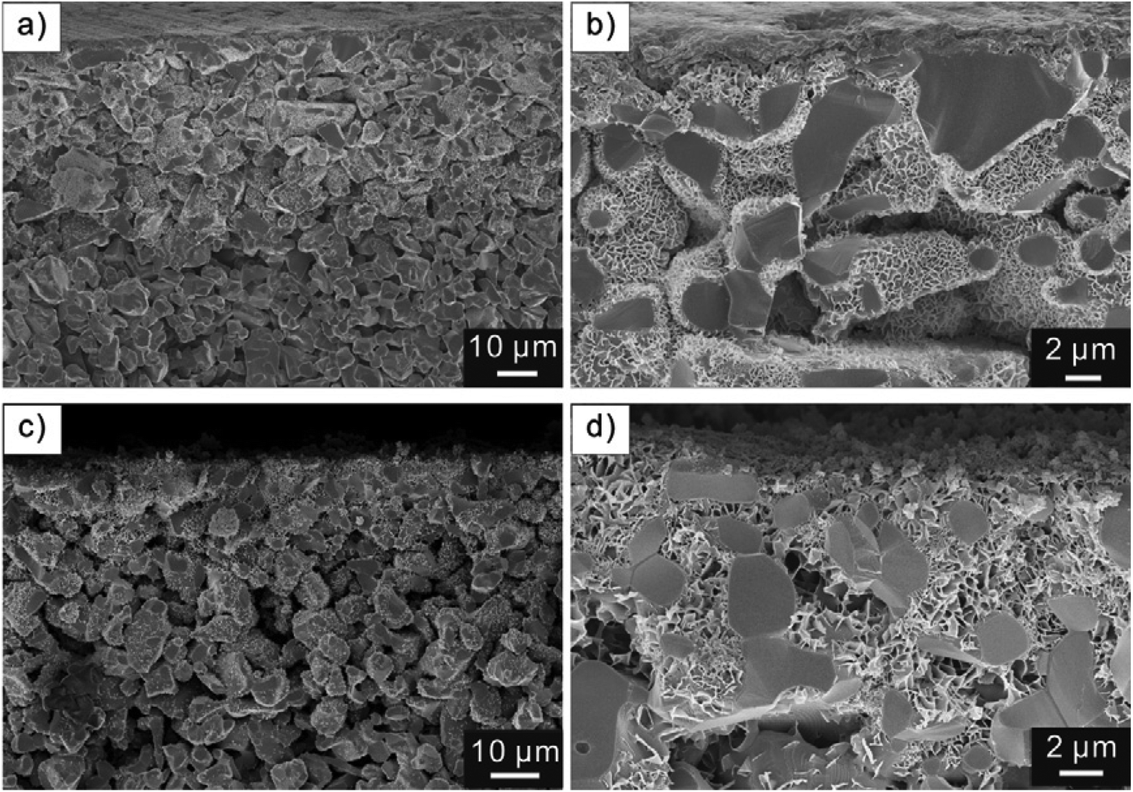 | ||
| Fig. 8 Representative examples of SEM images of the cross-sections of [Cu2(ndc)2(dabco)] on alumina (a and b) and of [Cu2(BME-bdc)2(dabco)] on titania substrates (c and d) at different magnifications. [Reprinted with permission from ref. 66. Copyright 2012 Elsevier.] | ||
An alternative way to combine the stepwise growth approach with membrane-based separation is to use this technique to seed the substrates. Subsequently, using a secondary hydro/solvothermal growth method, a uniform homogeneous MOF membrane could be achieved. Secondary seeding growth has been chosen for the fabrication of a variety of zeolite and MOF membranes because heterogeneous seeds can not only trigger MOF formation but can also promote faster growth, which could be described as crystallization “facilitators”.31,32 However, the seeds themselves are required to be nano-sized patches of the target MOFs, which are inherently constrained to the limits of efficient synthesis of the corresponding MOFs. The stepwise growth approach could offer a uniform thin layer on the substrates that could be used as a seeding layer for the secondary growth of MOF membranes. For example, continuous and defect-free Ni-MOF-74 membranes were successfully obtained by Lee et al.67 following the combined growth approach. The gas permeation properties of the membranes were investigated for different gases, such as H2, N2, CH4 and CO2. It was shown that the H2/CO2 ideal separation factor (∼9.1) exceeded the Knudsen selectivity, which suggests that the Ni-MOF-74 membrane is suitable for CO2 capture in the H2/CO2 separation. Nan et al.65 also used this combined method to prepare a [Cu3(btc)2] membrane to achieve gas separation. The separation factors of this membrane for H2 over CH4, N2, and CO2 are 3, 3.7 and 4.6, respectively, which are similar to the corresponding Knudsen selectivities because the pore opening of [Cu3(btc)2] (ca. 9 Å) is much larger than the kinetics diameters of H2 (2.9 Å), CH4 (3.8 Å), N2 (3.6 Å) and CO2 (3.3 Å).
In the case of the [Cu3(btc)2] coated capillary,68 as shown in Fig. 9a, the baseline separation between all the five components of natural gas can also be achieved. In comparison with the optimized performance of the [Zn4O(bdc)3] column, the natural gas chromatogram of the [Cu3(btc)2] column exhibits certain deficiencies, such as the strong peak tailing, the broadness of the isobutane peak, and the increased retention times for all analytes. However, as seen from Fig. 9b, the BTEX aromatics (benzene, toluene, p,o,m-xylene and ethylbenzene) could be separated efficiently by the [Cu3(btc)2] based column, while many chromatographic columns are not able to separate these compounds efficiently due to the very close boiling points of them. Additionally, a [Cu2(bdc)2(dabco)] coated PLOT column can be prepared by the same technique, which exhibits efficient separation of light hydrocarbon C1–C7 molecules.69
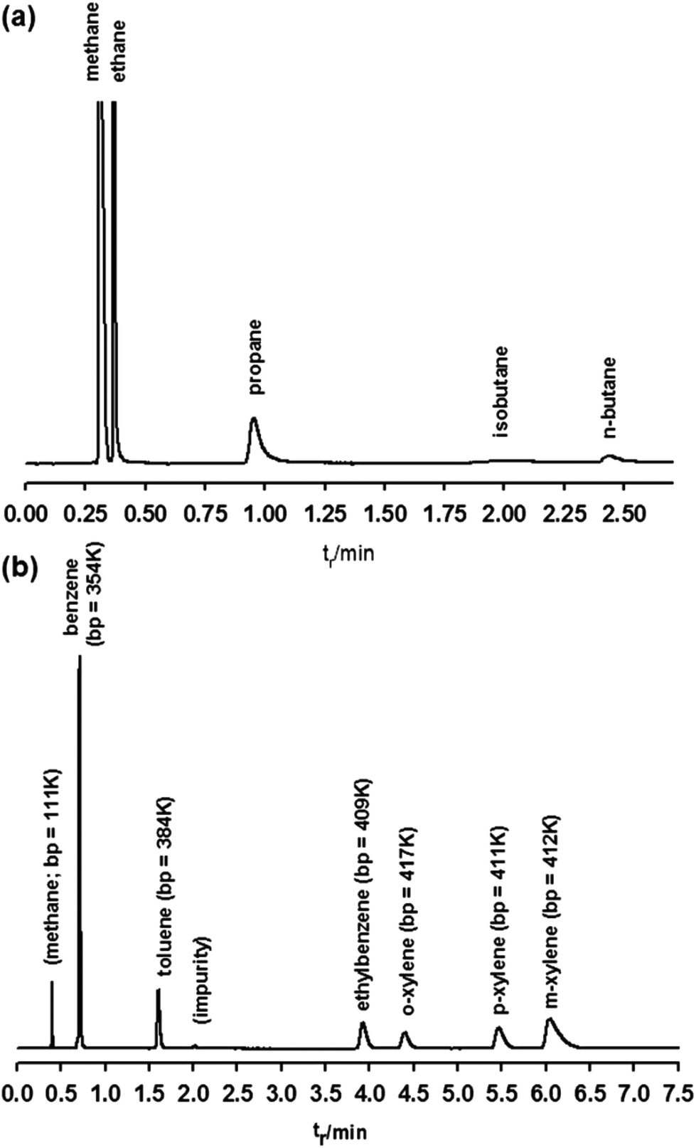 | ||
| Fig. 9 Chromatograms of natural gas (a) and aromatic compound mixtures (b) obtained using a [Cu3(btc)2] coated chromatographic column. Parameter settings: (a) carrier: He, flow: 11.0 ml min−1, oven: 40 °C for 1.3 min and then programmed at 70 K min−1 to 75 °C, injector: split 4.64:1 at 250 °C, detector: FID at 250 °C; (b) carrier: He, flow: 3.95 ml min−1, oven: isothermal, 180 °C, injector: split 13:1 at 250 °C, detector: FID at 250 °C. [Reproduced from ref. 68 with permission from the Royal Society of Chemistry.] | ||
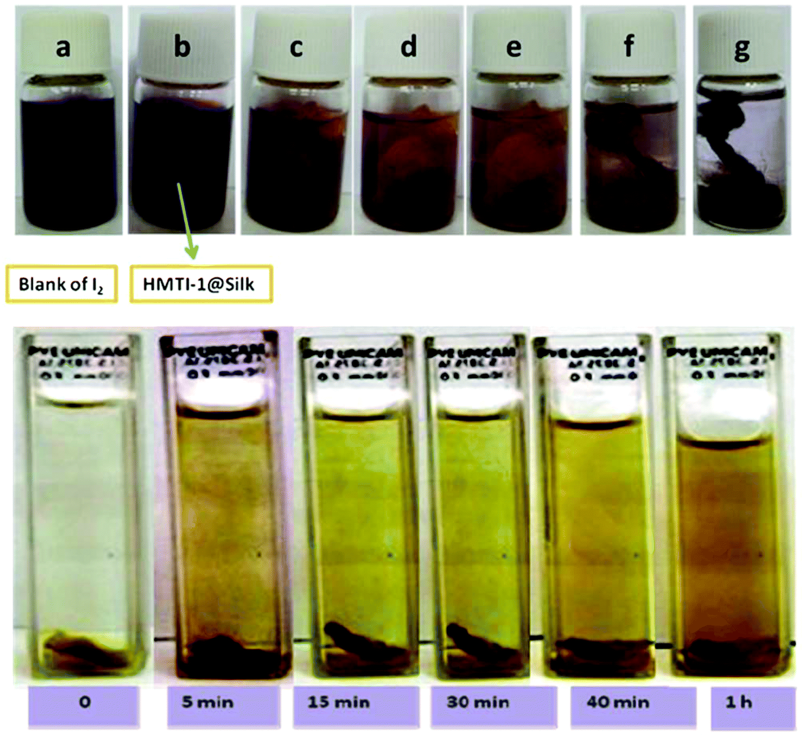 | ||
| Fig. 10 Upper: I2 enrichment progress by HMTI-1@silk in (a) blank, (b) immediately, (c) 3 min, (d) 5 min, (d) 20 min, (e) 30 min, (f) 1 h and (g) 2 h; down: progress of iodine release from I2@HMTI-1@silk when immersed in ethanol. [Reproduced from ref. 71 with permission from the Royal Society of Chemistry.] | ||
4.2 Development of chemical sensors
The sensitive and selective detection of gas and vapor phase analytes has attracted great interest for a range of applications, including industrial process management and environmental monitoring. MOF properties can be tailored with respect to framework pore size/shape and surface functionality and can show tunable responses and switching properties in response to external stimuli (such as temperature, pressure, electric potential, acoustic waves, and the chemical environment), providing selectivity and sensitivity to detect particular analytes.16 Generally, to employ MOFs for chemical sensing, except those based on luminescence quenching, some external means of signal transduction must be applied. Several means of transduction, including optical,75,76 electrical,77,117 and mechanical schemes,73 could be incorporated into MOFs for chemical detection. Many signal transduction schemes require a physical interface between the MOF and a device. This interface generally involves fabricating the MOFs as thin films on surfaces. The optimization of thin film thickness is essential because a thinner film causes lower selectivity, while a thicker film requires a longer response time (longer equilibrium time). Considering the aforementioned issues, several sensor devices were developed by the fabrication of MOFs on given substrates employing stepwise growth. Depending on the transduction mechanism, chemical detection applications utilizing MOFs are classified into 4 categories: (1) electromechanical sensors, (2) colloidal crystal-based sensors, (3) localized surface plasmon resonance, and (4) luminescence-based sensors.Surface acoustic wave (SAW) sensors have been widely used as robust mass sensing devices by monitoring the frequency shift of acoustic wave transport parallel to the surface that is generated by an oscillator. Thus, they are useful for sensitively detecting the mass change of MOFs deposited on the surface. Robinson et al.77 reported humidity detection over a very broad concentration range using a SAW sensor with a stepwise deposited thin layer of [Cu3(btc)2]. Humidity ranging from 2.6 to 12300 ppmv (corresponding to frost points from −70 to 10 °C at an atmospheric pressure of 625 torr) could be detected. Interestingly, the manually hand-dipped [Cu3(btc)2] SAW sensor with higher rms roughness shows a broader detection range (0.28 to 14800 ppmv). This improvement has not been explained by the authors. Therefore, a further systematic investigation of the effect of film morphology on sensor performance is strongly recommended. The sensing performance also depends on the thickness of the MOF coating, as the thinner coating has lower sensitivity, while the thicker coating shows a longer response time for reaching equilibrium. To optimize the thickness of the [Cu3(btc)2] coating for detecting humidity, the sensor response as a function of thickness corresponding to the number of deposition cycles was evaluated. As shown in Fig. 11, for 20 and 30 cycles of coating, corresponding to 70 and 100 nm thicknesses, the response is poor with lower sensitivity. The response to lower humidity does not increase after 50 cycles, indicating the optimal thickness to be 175 nm. These results demonstrate 3 orders of magnitude better response to humidity using [Cu3(btc)2] in comparison with the same coating on QCM substrates.117,154
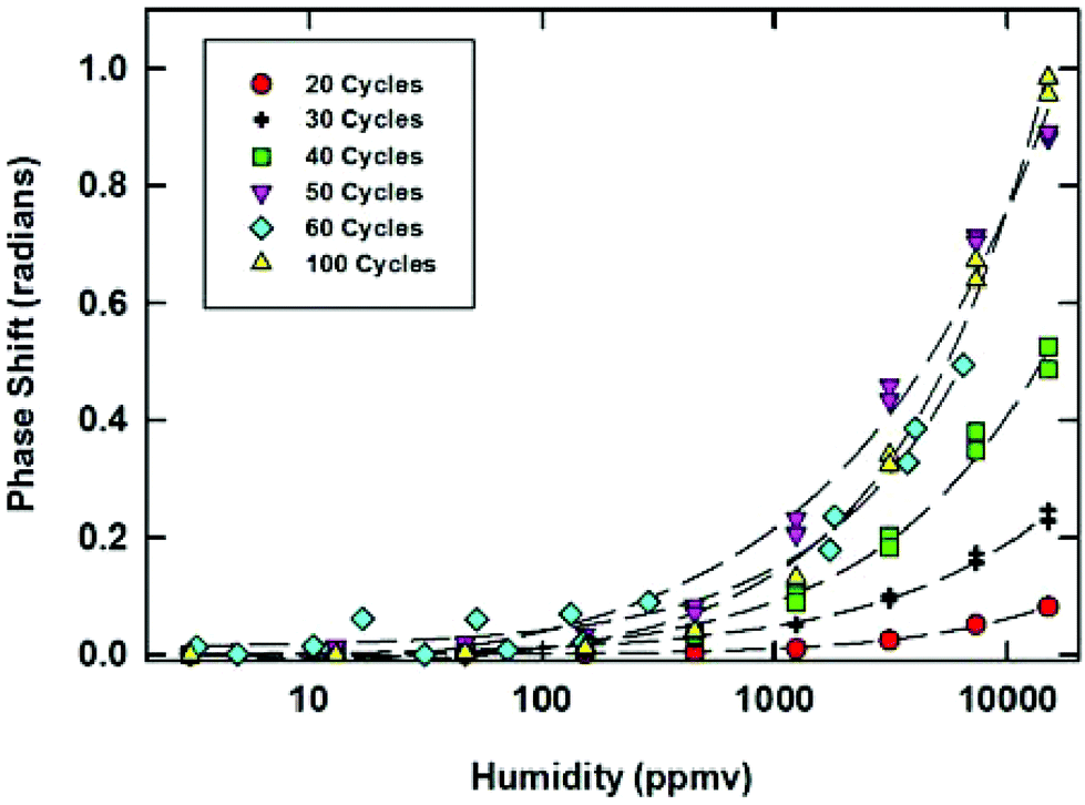 | ||
| Fig. 11 Response of [Cu3(btc)2] coated SAWs with different numbers of growth cycles to various humidity levels. [Reprinted with permission from ref. 77. Copyright 2013 American Chemistry Society.] | ||
000 ppm. Fig. 12b shows the responses of the sensor to CS2 at various concentrations, demonstrating a fast (second scale) and reversible response to the analyte. Based on the peak shift of the lowest concentration (100 ppm), together with the high-resolution spectrometer (with a shift resolution of 0.015 nm), the potential detection limits for H2O, EtOH and CS2 were estimated to be 2.6, 0.3 and 0.5, respectively. The shift also depends on the analyte concentration because the change in refractive index increases with increasing amounts of adsorbed molecules until reaching adsorption equilibrium (Fig. 12b,c). The adsorption curves obtained by converting the stop band shifts to normalized volume fractions of adsorbates are similar to the adsorption isotherm recorded by the QCM technique for a [Cu3(btc)2] film (Fig. 12d,e). Due to the porous nature of [Cu3(btc)2], the sensor could also respond to various gases, including Ar, CO2, C2H6, C2H4 and ambient air (Fig. 12f).
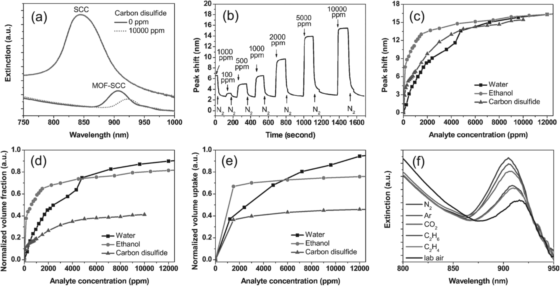 | ||
| Fig. 12 (a) Near-IR extinction spectra of the [Cu3(btc)2]-silica colloidal crystal thin film and the unmodified colloidal crystal thin film before and after exposure to 10000 ppm carbon disulfide. (b) Responses of [Cu3(btc)2]-silica colloidal crystal thin film to a series of carbon disulfide vapors of various concentrations versus time. (c) Dependence of the stop-band shift of the [Cu3(btc)2]-silica colloidal crystal thin film on the concentrations of vapors of water, ethanol, and carbon disulfide and (d) corresponding normalized vapor adsorption curves. (e) Normalized vapor adsorption curves for water, ethanol, and carbon disulfide by [Cu3(btc)2] thin film grown on a quartz crystal microbalance electrode. (f) Near-IR extinction spectra of [Cu3(btc)2]-silica colloidal crystal thin film upon exposure to various gases, showing a stop band at 904 nm for nitrogen, 905 nm for argon, 907 nm for carbon dioxide, 909 nm for ethane, 910 nm for ethylene, and 917 nm for laboratory air, respectively. [Reprinted with permission from ref. 75. Copyright 2011 Willy-VCH.] | ||
Wu et al.76 deposited [Cu3(btc)2] on another type of colloidal crystal substrate (monodispersed polystyrene, PS) using the stepwise growth approach. The responses of the photonic thin film upon exposure to various organic vapors (methanol, ethanol, isopropanol, hexane and octane) were detected. Interestingly, red shifts are observed for hexane and octane vapors, while blue shifts are observed for the alcohols. This result is attributed to different interactions between guest molecules and the framework of [Cu3(btc)2]. The detections of all vapors by the [Cu3(btc)2] incorporated PS colloidal arrays are fully recoverable. However, the detected types of organic vapors are limited by the PS dissolution problem.
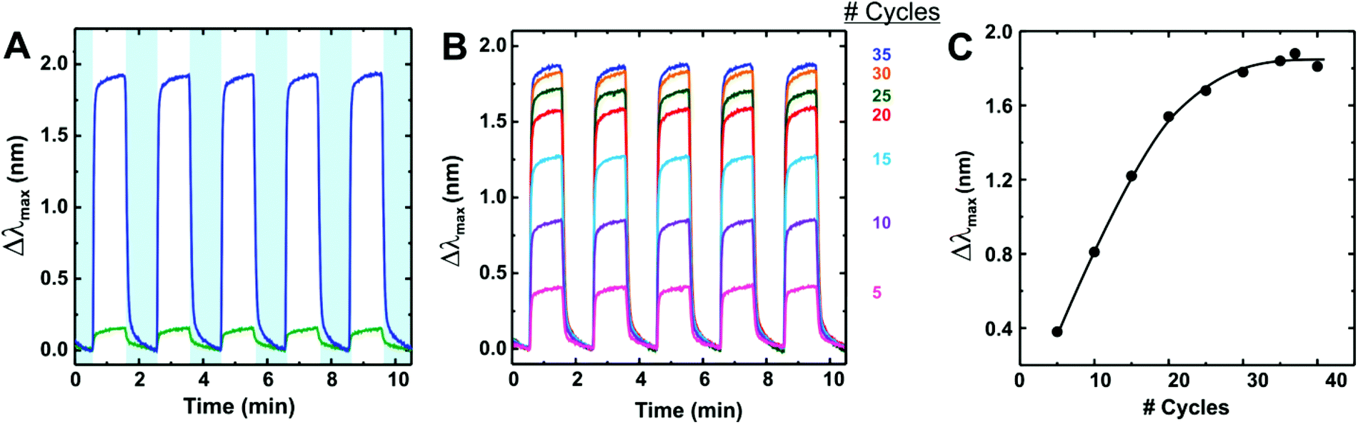 | ||
| Fig. 13 (A) Comparison of bare Ag nanoparticle sensor (green) and [Cu3(btc)2]-coated sensor (blue) response to CO2. (B) [Cu3(btc)2] sensor response to CO2 for increasing number of growth cycles. In both (A) and (B), CO2 was dosed for 60 s five times to show reversibility when the sample is purged with N2. (C) Average peak shift (Δλmax) as a function of the number of growth cycles. [Reprinted with permission from ref. 74. Copyright 2010 American Chemistry Society.] | ||
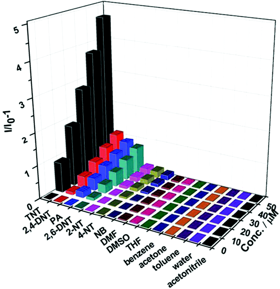 | ||
| Fig. 14 Fluorescence quenching results of nitroaromatic explosives (TNT, 2,4-DNT, PA, 2,6-DNT, 2-NT and NB) and commonly found interferents, including DMF, DMSO, THF, benzene, acetone, toluene, water and acetonitrile, to the emission of Fe3O4@Tb-BTC nanospheres at various concentrations in ethanol. [Reproduced from ref. 79 with permission from the Royal Society of Chemistry.] | ||
4.3 Development of catalysts
As we had mentioned before, the incorporation of nano- and microparticles into porous MOFs provides additional functionalities, such as magnetic, luminescent and catalytic properties. With the preformed micro/nanoparticles route to prepare functional composites, there has been a flurry of recent activity demonstrating the ability to use these materials in various applications.157 The controlled localization of preformed MOFs incorporating magnetic particles allows the positioning of single MOF functional particles in precise locations by an external magnetic field.86Qiu and coworkers80 reported the encapsulation of Au nanoparticles by the MIL-100(Fe) coupling stepwise growth method, yielding Au@MIL-100(Fe) core–shell nanoparticles for the catalytic conversion of 4-nitrophenol (4-NP) to 4-aminophenol (4-AP). The complete reduction of 4-NP by Au@MIL-100(Fe) was achieved within 15 min, whereas a much longer time was required over pure Au (220 min) and MIL-100 (110 min) nanoparticles. The core–shell structure shows enhanced catalytic activity in comparison with pure Au, which is attributed to the function of the MIL-100(Fe) shell, in which 4-NP was adsorbed at a high concentration, increasing the probability of contact with the catalyst.
Another type of core–shell structure with the integration of magnetic Fe3O4 nanoparticles and MIL-100(Fe) was fabricated by Qiu and coworkers (Fig. 15).53,81 Industrially promising functional composites are obtained by incorporating magnetic nanoparticles and nanofibers into MOF frameworks to allow control over the position of the particles. Stepwise grown Fe3O4@MIL-100(Fe) core–shell microspheres were used for the photocatalytic decolorization of methylene blue (MB) dye and the Claisen–Schmidt condensation reaction. In the case of the decolorization of MB under UV and visible light radiation, the Fe3O4@MIL-100(Fe) core–shell microspheres exhibit enhanced photocatalytic activity compared to conventional photocatalysts, such as TiO2 and C3N4. Although the photocatalytic performance of the functional composite Fe3O4@MIL-100(Fe) is similar to the undecorated MIL-100 (Fe), the as-synthesized material exhibited good magnetic characteristics, which can be easily separated from solutions by a magnetic field, making it an excellent candidate for designing and synthesizing a novel type of highly active photocatalyst under visible light for the decolorization of organic pollutants in waste water. No obvious loss of activity for MB decolorization was observed over Fe3O4@MIL-100(Fe) during five cycles, indicating that the Fe3O4@MIL-100(Fe) possesses excellent long-term stability.
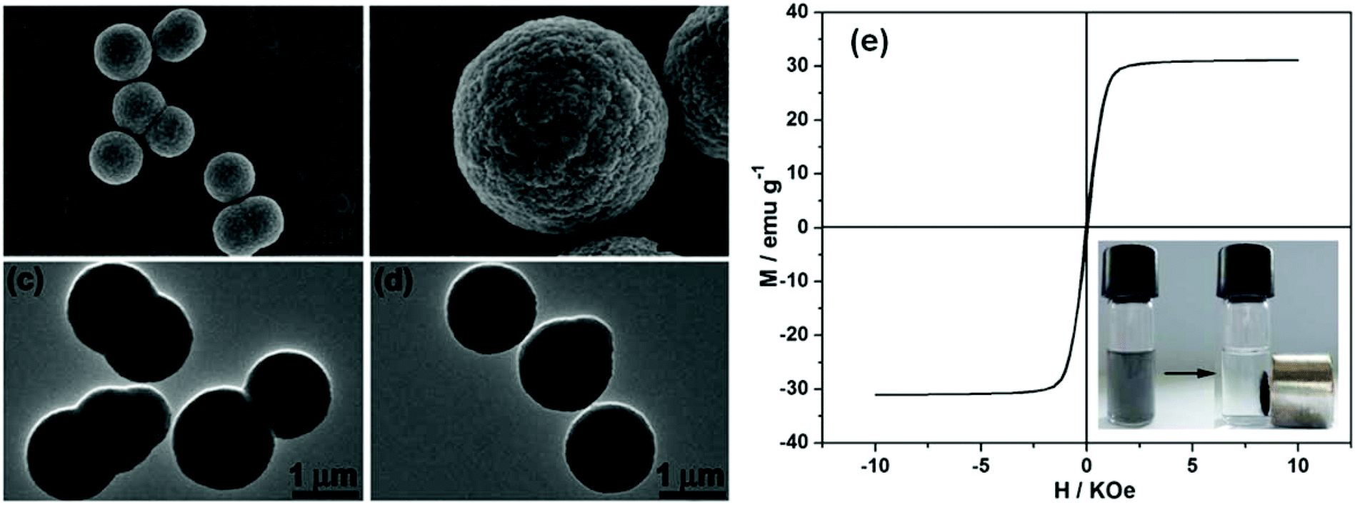 | ||
| Fig. 15 SEM images (a and b) and TEM images (c and d) of Fe3O4@MIL-100(Fe) core–shell magnetic microspheres after 40 assembly cycles by a stepwise strategy. (e) Magnetic hysteresis loop of Fe3O4@MIL-100(Fe) core–shell microspheres. The photographs in the inset demonstrate the convenient separation process of the catalysts by an external magnet. [Reproduced from ref. 81 with permission from the Royal Society of Chemistry.] | ||
The Fe3O4@MIL-100(Fe) core–shell microspheres were also tested for the Claisen–Schmidt condensation reaction.81 As shown in Table 2, they exhibit remarkable catalytic activities for the reaction between benzaldehyde and aromatic ketones, which are higher than or comparable with the reported MIL-100(Fe) catalysts,158 indicating that the incorporation of magnetic Fe3O4 does not affect the catalytic activity of MIL-100(Fe) itself but provides a magnetic property for separation and recovery from the reaction mixture.


5 Conclusion and perspectives
The field of MOF films shows great potential for practical applications. As one of the promising methods for MOF film deposition, several MOF films or coatings can be fabricated on various substrates for fundamental studies, including growth mechanism, porosity, conductivity, light harvesting, mechanical and optical properties. These investigations are important for processing MOF films or coating into practical applications. For instance, based on the understanding of the significant role of SBUs in the fabrication of a stepwise grown [Cu3(btc)2] film, other types of MOF films were fabricated employing the so-called controllable SBU approach (CSA). However, stepwise growth employing preformed SBUs is not required for every MOF film. For example, MIL-100(Fe)53 was successfully grown on –COOH terminated Fe3O4 nanoparticles using FeCl3 as a metal source without using preformed iron SBU as the metal source. Further investigation is strongly required for an in-depth understanding of the growth mechanism. The properties of the MOF films arise mainly from the bulk materials, but some of the properties may differ when they are grown on surfaces. It is noteworthy that certain properties could be achieved and thoroughly investigated only when the MOFs were fabricated as thin films on the substrates. Although the aforementioned properties of MOF films were investigated, investigation of other fundamental properties is still recommended, including chemical and thermal stability as well as the adhesion between films and the corresponding substrates. The chemical and thermal stability may be obtained directly from the bulk materials, but the properties of the film itself may be affected by chemical and thermal treatment. For example, due to the difference in the coefficient of thermal expansion between MOF layers and the given substrates, the formation of cracks, holes and defects may result without the decomposition of MOFs upon cooling or heating, which would significantly affect the properties of MOF films and consequently lead to failure in realistic applications. Therefore, further investigation of these properties is also strongly encouraged.Even though the stepwise deposition approach shows its efficiency in thin film fabrication, in comparison with the large number of reported MOF bulk materials, only a limited number of MOFs were grown on surfaces by this method. The development of other types of MOF films (such as ZIFs and UIO-66 serials) is encouraged for the enrichment of the MOF films library due to their high chemical and thermal stability, which are important for commercial applications. Recently, a ZIF-8 [Zn(mim)2] thin film was achieved by Shekhah et al. using this approach.55 This result may indicate that stepwise deposition growth could be applied to other interesting ZIFs to develop potential applications. Additionally, considering that the controlled SBU approach has been applied in the synthesis of robust bulk UIO-66,159 this type of MOF, as well as its derivatives, may be fabricated as thin films using the stepwise growth approach. Nevertheless, many growth parameters need to be considered and optimized in the stepwise growth, such as the metal source, concentration of the reactant, solvent, temperature, reaction time and the sequence of dosing. Hence, a systematic investigation is required for obtaining suitable fabrication parameters for each specific type of MOF film and substrate.
Due to the homogeneous nature and controllable thickness of stepwise grown MOF films, several applications, such as separation, chemical sensing and catalysis, could be achieved by depositing them on given substrates for the target applications. However, these applications are still in lab scale. Thus, to employ them in industrial applications, a large number of issues, including scaling up, automation, economic, and environmental factors, should be taken into account. We expect that more applications of stepwise grown MOF films could be achieved, not only in the aforementioned fields but also in other novel applications, such as solar cells, electrodes, fuel cells, and drug delivery.
Acknowledgements
This work was funded within the Priority Program 1362 “Metal–Organic Frameworks” of the German Research Foundation (DFG). M. T. is grateful for a PhD fellowship from the China Scholarship Council (CSC). S. W. is grateful for master and PhD scholarships from the Royal Thai Government under the Ministry of Science and Technology.Notes and references
- S. R. Batten, N. R. Champness, X.-M. Chen, J. Garcia-Martinez, S. Kitagawa, L. Öhrström, M. O'Keeffe, M. P. Suh and J. Reedijk, Pure Appl. Chem., 2013, 85, 1715 CrossRef CAS.
- S. R. Batten, N. R. Champness, X.-M. Chen, J. Garcia-Martinez, S. Kitagawa, L. Öhrström, M. O'Keeffe, M. P. Suh and J. Reedijk, CrystEngComm, 2012, 14, 3001 RSC.
- O. M. Yaghi and H. Li, J. Am. Chem. Soc., 1995, 117, 10401 CrossRef CAS.
- O. M. Yaghi, G. Li and H. Li, Nature, 1995, 378, 703 CrossRef CAS.
- H. Furukawa, N. Ko, Y. B. Go, N. Aratani, S. B. Choi, E. Choi, A. Ö. Yazaydin, R. Q. Snurr, M. O'Keeffe, J. Kim and O. M. Yaghi, Science, 2010, 329, 424 CrossRef CAS PubMed.
- O. K. Farha, I. Eryazici, N. C. Jeong, B. G. Hauser, C. E. Wilmer, A. A. Sarjeant, R. Q. Snurr, S. T. Nguyen, A. Ö. Yazaydın and J. T. Hupp, J. Am. Chem. Soc., 2012, 134, 15016 CrossRef CAS PubMed.
- M. Yoon, R. Srirambalaji and K. Kim, Chem. Rev., 2012, 112, 1196 CrossRef CAS PubMed.
- M. Kurmoo, Chem. Soc. Rev., 2009, 38, 1353 RSC.
- Y. Cui, Y. Yue, G. Qian and B. Chen, Chem. Rev., 2012, 112, 1126 CrossRef CAS PubMed.
- G. J. Halder, C. J. Kepert, B. Moubaraki, K. S. Murray and J. D. Cashion, Science, 2002, 298, 1762 CrossRef CAS PubMed.
- Y.-C. Chuang, C.-T. Liu, C.-F. Sheu, W.-L. Ho, G.-H. Lee, C.-C. Wang and Y. Wang, Inorg. Chem., 2012, 51, 4663 CrossRef CAS PubMed.
- A. Morozan and F. Jaouen, Energy Environ. Sci., 2012, 5, 9269 CAS.
- M. Yoon, K. Suh, S. Natarajan and K. Kim, Angew. Chem., Int. Ed., 2013, 52, 2688 CrossRef CAS PubMed.
- G. Givaja, P. Amo-Ochoa, C. J. Gomez-Garcia and F. Zamora, Chem. Soc. Rev., 2012, 41, 115 RSC.
- P. Horcajada, R. Gref, T. Baati, P. K. Allan, G. Maurin, P. Couvreur, G. Férey, R. E. Morris and C. Serre, Chem. Rev., 2012, 112, 1232 CrossRef CAS PubMed.
- L. E. Kreno, K. Leong, O. K. Farha, M. Allendorf, R. P. Van Duyne and J. T. Hupp, Chem. Rev., 2012, 112, 1105 CrossRef CAS PubMed.
- J.-R. Li, J. Sculley and H.-C. Zhou, Chem. Rev., 2012, 112, 869 CrossRef CAS PubMed.
- M. P. Suh, H. J. Park, T. K. Prasad and D.-W. Lim, Chem. Rev., 2012, 112, 782 CrossRef CAS PubMed.
- K. Sumida, D. L. Rogow, J. A. Mason, T. M. McDonald, E. D. Bloch, Z. R. Herm, T.-H. Bae and J. R. Long, Chem. Rev., 2012, 112, 724 CrossRef CAS PubMed.
- C. Wang, T. Zhang and W. Lin, Chem. Rev., 2012, 112, 1084 CrossRef CAS PubMed.
- H. Wu, Q. Gong, D. H. Olson and J. Li, Chem. Rev., 2012, 112, 836 CrossRef CAS PubMed.
- Z. R. Herm, E. D. Bloch and J. R. Long, Chem. Mater., 2013, 26, 323 CrossRef.
- C. Janiak and J. K. Vieth, New J. Chem., 2010, 34, 2366 RSC.
- S.-L. Li and Q. Xu, Energy Environ. Sci., 2013, 6, 1656 CAS.
- J.-L. Wang, C. Wang and W. Lin, ACS Catal., 2012, 2, 2630 CrossRef CAS.
- K. J. Gagnon, H. P. Perry and A. Clearfield, Chem. Rev., 2012, 112, 1034 CrossRef CAS PubMed.
- N. Stock and S. Biswas, Chem. Rev., 2012, 112, 933 CrossRef CAS PubMed.
- J.-P. Zhang, Y.-B. Zhang, J.-B. Lin and X.-M. Chen, Chem. Rev., 2012, 112, 1001 CrossRef CAS PubMed.
- S. M. Cohen, Chem. Rev., 2012, 112, 970 CrossRef CAS PubMed.
- M. L. Foo, R. Matsuda and S. Kitagawa, Chem. Mater., 2013, 26, 310 CrossRef.
- J. Caro, Curr. Opin. Chem. Eng., 2011, 1, 77 CrossRef CAS.
- M. Shah, M. C. McCarthy, S. Sachdeva, A. K. Lee and H.-K. Jeong, Ind. Eng. Chem. Res., 2011, 51, 2179 CrossRef.
- M. D. Allendorf, A. Schwartzberg, V. Stavila and A. A. Talin, Chem. – Eur. J., 2011, 17, 11372 CrossRef CAS PubMed.
- A. Bétard and R. A. Fischer, Chem. Rev., 2012, 112, 1055 CrossRef PubMed.
- B. Liu, J. Mater. Chem., 2012, 22, 10094 RSC.
- A. A. Talin, A. Centrone, A. C. Ford, M. E. Foster, V. Stavila, P. Haney, R. A. Kinney, V. Szalai, F. El Gabaly, H. P. Yoon, F. Léonard and M. D. Allendorf, Science, 2014, 343, 66 CrossRef CAS PubMed.
- C. H. Hendon, D. Tiana and A. Walsh, Phys. Chem. Chem. Phys., 2012, 14, 13120 RSC.
- R. Ameloot, E. Gobechiya, H. Uji-i, J. A. Martens, J. Hofkens, L. Alaerts, B. F. Sels and D. E. De Vos, Adv. Mater., 2010, 22, 2685 CrossRef CAS PubMed.
- G. Lu and J. T. Hupp, J. Am. Chem. Soc., 2010, 132, 7832 CrossRef CAS PubMed.
- M. Kubo, W. Chaikittisilp and T. Okubo, Chem. Mater., 2008, 20, 2887 CrossRef CAS.
- H. T. Kwon and H.-K. Jeong, J. Am. Chem. Soc., 2013, 135, 10763 CrossRef CAS PubMed.
- Y.-S. Li, H. Bux, A. Feldhoff, G.-L. Li, W.-S. Yang and J. Caro, Adv. Mater., 2010, 22, 3322 CrossRef CAS PubMed.
- L. Dumee, L. He, M. Hill, B. Zhu, M. Duke, J. Schutz, F. She, H. Wang, S. Gray, P. Hodgson and L. Kong, J. Mater. Chem. A, 2013, 1, 9208 CAS.
- Y.-S. Li, F.-Y. Liang, H. Bux, A. Feldhoff, W.-S. Yang and J. Caro, Angew. Chem., Int. Ed., 2010, 49, 548 CrossRef CAS PubMed.
- C. M. Doherty, G. Grenci, R. Riccò, J. I. Mardel, J. Reboul, S. Furukawa, S. Kitagawa, A. J. Hill and P. Falcaro, Adv. Mater., 2013, 25, 4701 CrossRef CAS PubMed.
- O. Shekhah, H. Wang, S. Kowarik, F. Schreiber, M. Paulus, M. Tolan, C. Sternemann, F. Evers, D. Zacher, R. A. Fischer and C. Wöll, J. Am. Chem. Soc., 2007, 129, 15118 CrossRef CAS PubMed.
- K. Kanaizuka, R. Haruki, O. Sakata, M. Yoshimoto, Y. Akita and H. Kitagawa, J. Am. Chem. Soc., 2008, 130, 15778 CrossRef CAS PubMed.
- C. Munuera, O. Shekhah, H. Wang, C. Wöll and C. Ocal, Phys. Chem. Chem. Phys., 2008, 10, 7257 RSC.
- O. Shekhah, H. Wang, M. Paradinas, C. Ocal, B. Schupbach, A. Terfort, D. Zacher, R. A. Fischer and C. Wöll, Nat. Mater., 2009, 8, 481 CrossRef CAS PubMed.
- H. K. Arslan, O. Shekhah, D. C. F. Wieland, M. Paulus, C. Sternemann, M. A. Schroer, S. Tiemeyer, M. Tolan, R. A. Fischer and C. Wöll, J. Am. Chem. Soc., 2011, 133, 8158 CrossRef CAS PubMed.
- H. K. Arslan, O. Shekhah, J. Wohlgemuth, M. Franzreb, R. A. Fischer and C. Wöll, Adv. Funct. Mater., 2011, 21, 4228 CrossRef CAS.
- B. Liu, M. Ma, D. Zacher, A. Bétard, K. Yusenko, N. Metzler-Nolte, C. Wöll and R. A. Fischer, J. Am. Chem. Soc., 2011, 133, 1734 CrossRef CAS PubMed.
- F. Ke, L.-G. Qiu, Y.-P. Yuan, X. Jiang and J.-F. Zhu, J. Mater. Chem., 2012, 22, 9497 RSC.
- K. Otsubo, T. Haraguchi, O. Sakata, A. Fujiwara and H. Kitagawa, J. Am. Chem. Soc., 2012, 134, 9605 CrossRef CAS PubMed.
- O. Shekhah and M. Eddaoudi, Chem. Commun., 2013, 49, 10079 RSC.
- D. Witters, S. Vermeir, R. Puers, B. F. Sels, D. E. De Vos, J. Lammertyn and R. Ameloot, Chem. Mater., 2013, 25, 1021 CrossRef CAS.
- J. Liu, B. Lukose, O. Shekhah, H. K. Arslan, P. Weidler, H. Gliemann, S. Brase, S. Grosjean, A. Godt, X. L. Feng, K. Mullen, I. B. Magdau, T. Heine and C. Wöll, Sci. Rep., 2012, 2, 921 Search PubMed.
- M. Meilikhov, K. Yusenko, E. Schollmeyer, C. Mayer, H.-J. Buschmann and R. A. Fischer, Dalton Trans., 2011, 40, 4838 RSC.
- D. Zacher, K. Yusenko, A. Bétard, S. Henke, M. Molon, T. Ladnorg, O. Shekhah, B. Schüpbach, T. de los Arcos, M. Krasnopolski, M. Meilikhov, J. Winter, A. Terfort, C. Wöll and R. A. Fischer, Chem. – Eur. J., 2011, 17, 1448 CrossRef CAS PubMed.
- O. Shekhah, L. Fu, R. Sougrat, Y. Belmabkhout, A. J. Cairns, E. P. Giannelis and M. Eddaoudi, Chem. Commun., 2012, 48, 11434 RSC.
- K. Ariga, J. P. Hill and Q. Ji, Phys. Chem. Chem. Phys., 2007, 9, 2319 RSC.
- J.-E. Gu, S. Lee, C. M. Stafford, J. S. Lee, W. Choi, B.-Y. Kim, K.-Y. Baek, E. P. Chan, J. Y. Chung, J. Bang and J.-H. Lee, Adv. Mater., 2013, 25, 4778 CrossRef CAS PubMed.
- P. St. Petkov, G. N. Vayssilov, J. Liu, O. Shekhah, Y. Wang, C. Wöll and T. Heine, ChemPhysChem, 2012, 13, 2025 CrossRef CAS PubMed.
- A. S. Münch, J. Seidel, A. Obst, E. Weber and F. O. R. L. Mertens, Chem. – Eur. J., 2011, 17, 10958 CrossRef PubMed.
- J. Nan, X. Dong, W. Wang, W. Jin and N. Xu, Langmuir, 2011, 27, 4309 CrossRef CAS PubMed.
- A. Bétard, H. Bux, S. Henke, D. Zacher, J. Caro and R. A. Fischer, Microporous Mesoporous Mater., 2012, 150, 76 CrossRef.
- D.-J. Lee, Q. Li, H. Kim and K. Lee, Microporous Mesoporous Mater., 2012, 163, 169 CrossRef CAS.
- A. S. Münch and F. O. R. L. Mertens, J. Mater. Chem., 2012, 22, 10228 RSC.
- T. Böhle and F. Mertens, Microporous Mesoporous Mater., 2014, 183, 162 CrossRef.
- X. Chen, N. Ding, H. Zang, H. Yeung, R.-S. Zhao, C. Cheng, J. Liu and T. W. D. Chan, J. Chromatogr., A, 2013, 1304, 241 CrossRef CAS PubMed.
- S. Khanjani and A. Morsali, CrystEngComm, 2012, 14, 8137 RSC.
- M. Zhao, C. Deng, X. Zhang and P. Yang, Proteomics, 2013, 13, 3387 CrossRef CAS PubMed.
- M. D. Allendorf, R. J. T. Houk, L. Andruszkiewicz, A. A. Talin, J. Pikarsky, A. Choudhury, K. A. Gall and P. J. Hesketh, J. Am. Chem. Soc., 2008, 130, 14404 CrossRef CAS PubMed.
- L. E. Kreno, J. T. Hupp and R. P. Van Duyne, Anal. Chem., 2010, 82, 8042 CrossRef CAS PubMed.
- G. Lu, O. K. Farha, L. E. Kreno, P. M. Schoenecker, K. S. Walton, R. P. Van Duyne and J. T. Hupp, Adv. Mater., 2011, 23, 4449 CrossRef CAS PubMed.
- Y. N. Wu, F. T. Li, Y. X. Xu, W. Zhu, C. A. Tao, J. C. Cui and G. T. Li, Chem. Commun., 2011, 47, 10094 RSC.
- A. L. Robinson, V. Stavila, T. R. Zeitler, M. I. White, S. M. Thornberg, J. A. Greathouse and M. D. Allendorf, Anal. Chem., 2012, 84, 7043 CrossRef CAS PubMed.
- I. Ellern, A. Venkatasubramanian, J.-H. Lee, P. Hesketh, V. Stavila, A. Robinson and M. Allendorf, Micro Nano Lett., 2013, 8, 766 Search PubMed.
- J.-J. Qian, L.-G. Qiu, Y.-M. Wang, Y.-P. Yuan, A.-J. Xie and Y.-H. Shen, Dalton Trans., 2014, 43, 3978 RSC.
- F. Ke, J. Zhu, L.-G. Qiu and X. Jiang, Chem. Commun., 2013, 49, 1267 RSC.
- F. Ke, L.-G. Qiu and J. Zhu, Nanoscale, 2014, 6, 1596 RSC.
- C.-F. Zhang, L.-G. Qiu, F. Ke, Y.-J. Zhu, Y.-P. Yuan, G.-S. Xu and X. Jiang, J. Mater. Chem. A, 2013, 1, 14329 CAS.
- B. Liu and R. Fischer, Sci. China, Ser. B: Chem., 2011, 54, 1851 CrossRef CAS.
- H. Gliemann and C. Wöll, Mater. Today, 2012, 15, 110 CrossRef CAS.
- D. Bradshaw, A. Garai and J. Huo, Chem. Soc. Rev., 2012, 41, 2344 RSC.
- R. Ricco, L. Malfatti, M. Takahashi, A. J. Hill and P. Falcaro, J. Mater. Chem. A, 2013, 1, 13033 CAS.
- M. E. Silvestre, M. Franzreb, P. G. Weidler, O. Shekhah and C. Wöll, Adv. Funct. Mater., 2013, 23, 1210 CrossRef CAS.
- H. J. Lee, J.-U. Park, S. Choi, J. Son and M. Oh, Small, 2013, 9, 561 CrossRef CAS PubMed.
- A. Dhakshinamoorthy and H. Garcia, Chem. Soc. Rev., 2012, 41, 5262 RSC.
- M. Meilikhov, K. Yusenko, D. Esken, S. Turner, G. Van Tendeloo and R. A. Fischer, Eur. J. Inorg. Chem., 2010, 2010, 3701 CrossRef.
- K. Khaletskaya, J. Reboul, M. Meilikhov, M. Nakahama, S. Diring, M. Tsujimoto, S. Isoda, F. Kim, K.-i. Kamei, R. A. Fischer, S. Kitagawa and S. Furukawa, J. Am. Chem. Soc., 2013, 135, 10998 CrossRef CAS PubMed.
- C. M. Doherty, D. Buso, A. J. Hill, S. Furukawa, S. Kitagawa and P. Falcaro, Acc. Chem. Res., 2014, 47, 396 CrossRef CAS PubMed.
- O. Shekhah, H. Wang, D. Zacher, R. A. Fischer and C. Wöll, Angew. Chem., Int. Ed., 2009, 48, 5038 CrossRef CAS PubMed.
- V. Stavila, J. Volponi, A. M. Katzenmeyer, M. C. Dixon and M. D. Allendorf, Chem. Sci., 2012, 3, 1531 RSC.
- O. Zybaylo, O. Shekhah, H. Wang, M. Tafipolsky, R. Schmid, D. Johannsmann and C. Wöll, Phys. Chem. Chem. Phys., 2010, 12, 8093 RSC.
- D. Y. Lee, D. V. Shinde, S. J. Yoon, K. N. Cho, W. Lee, N. K. Shrestha and S.-H. Han, J. Phys. Chem. C, 2014 DOI:10.1021/jp4079663.
- A. Dragässer, O. Shekhah, O. Zybaylo, C. Shen, M. Buck, C. Wöll and D. Schlettwein, Chem. Commun., 2012, 48, 663 RSC.
- H. C. Streit, M. Adlung, O. Shekhah, X. Stammer, H. K. Arslan, O. Zybaylo, T. Ladnorg, H. Gliemann, M. Franzreb, C. Wöll and C. Wickleder, ChemPhysChem, 2012, 13, 2699 CrossRef CAS PubMed.
- S. Bundschuh, O. Kraft, H. K. Arslan, H. Gliemann, P. G. Weidler and C. Wöll, Appl. Phys. Lett., 2012, 101, 101910 CrossRef.
- E. Redel, Z. Wang, S. Walheim, J. Liu, H. Gliemann and C. Wöll, Appl. Phys. Lett., 2013, 103, 091903 CrossRef.
- A. Bétard, S. Wannapaiboon and R. A. Fischer, Chem. Commun., 2012, 48, 10493 RSC.
- B. Liu, O. Shekhah, H. K. Arslan, J. Liu, C. Wöll and R. A. Fischer, Angew. Chem., Int. Ed., 2012, 51, 807 CrossRef CAS PubMed.
- B. Liu, M. Tu and R. A. Fischer, Angew. Chem., Int. Ed., 2013, 52, 3402 CrossRef CAS PubMed.
- L. Heinke and C. Wöll, Phys. Chem. Chem. Phys., 2013, 15, 9295 RSC.
- M. Meilikhov, S. Furukawa, K. Hirai, R. A. Fischer and S. Kitagawa, Angew. Chem., Int. Ed., 2013, 52, 341 CrossRef CAS PubMed.
- B. Liu, M. Tu, D. Zacher and R. A. Fischer, Adv. Funct. Mater., 2013, 23, 3790 CrossRef CAS.
- M. Tu and R. A. Fischer, J. Mater. Chem. A, 2014, 2, 2018 CAS.
- O. Shekhah, R. Swaidan, Y. Belmabkhout, M. du Plessis, T. Jacobs, L. J. Barbour, I. Pinnau and M. Eddaoudi, Chem. Commun., 2014, 50, 2089 RSC.
- K. Szelagowska-Kunstman, P. Cyganik, M. Goryl, D. Zacher, Z. Puterova, R. A. Fischer and M. Szymonski, J. Am. Chem. Soc., 2008, 130, 14446 CrossRef CAS PubMed.
- M. Shoaee, J. R. Agger, M. W. Anderson and M. P. Attfield, CrystEngComm, 2008, 10, 646 RSC.
- J. A. Rood, W. C. Boggess, B. C. Noll and K. W. Henderson, J. Am. Chem. Soc., 2007, 129, 13675 CrossRef CAS PubMed.
- S. Surble, F. Millange, C. Serre, G. Férey and R. I. Walton, Chem. Commun., 2006, 1518 RSC.
- A. S. Münch, M. S. Lohse, S. Hausdorf, G. Schreiber, D. Zacher, R. A. Fischer and F. O. R. L. Mertens, Microporous Mesoporous Mater., 2012, 159, 132 CrossRef.
- S. Wannapaiboon, M. Tu and R. A. Fischer, Adv. Funct. Mater., 2014, 24, 2696 CrossRef CAS.
- M. Tu, S. Wannapaiboon and R. A. Fischer, Dalton Trans., 2013, 42, 16029 RSC.
- H. Bux, C. Chmelik, J. M. van Baten, R. Krishna and J. Caro, Adv. Mater., 2010, 22, 4741 CrossRef CAS PubMed.
- E. Biemmi, A. Darga, N. Stock and T. Bein, Microporous Mesoporous Mater., 2008, 114, 380 CrossRef CAS.
- S. Eslava, M. R. Baklanov, C. E. A. Kirschhock, F. Iacopi, S. Aldea, K. Maex and J. A. Martens, Langmuir, 2007, 23, 12811 CrossRef CAS PubMed.
- A. Demessence, C. Boissiere, D. Grosso, P. Horcajada, C. Serre, G. Ferey, G. J. A. A. Soler-Illia and C. Sanchez, J. Mater. Chem., 2010, 20, 7676 RSC.
- S. Eslava, L. Zhang, S. Esconjauregui, J. Yang, K. Vanstreels, M. R. Baklanov and E. Saiz, Chem. Mater., 2012, 25, 27 CrossRef.
- G. Nickerl, A. Henschel, R. Grünker, K. Gedrich and S. Kaskel, Chem. Ing. Tech., 2011, 83, 90 CrossRef CAS.
- Y. Liu, W. Xuan and Y. Cui, Adv. Mater., 2010, 22, 4112 CrossRef CAS PubMed.
- W. Wang, X. Dong, J. Nan, W. Jin, Z. Hu, Y. Chen and J. Jiang, Chem. Commun., 2012, 48, 7022 RSC.
- Z. Kang, M. Xue, L. Fan, J. Ding, L. Guo, L. Gao and S. Qiu, Chem. Commun., 2013, 49, 10569 RSC.
- K. Huang, X. Dong, R. Ren and W. Jin, AIChE J., 2013, 59, 4364 CrossRef CAS.
- Z. Lai, G. Bonilla, I. Diaz, J. G. Nery, K. Sujaoti, M. A. Amat, E. Kokkoli, O. Terasaki, R. W. Thompson, M. Tsapatsis and D. G. Vlachos, Science, 2003, 300, 456 CAS.
- H. Bux, A. Feldhoff, J. Cravillon, M. Wiebcke, Y.-S. Li and J. Caro, Chem. Mater., 2011, 23, 2262 CrossRef CAS.
- H. Zhou, X. Chen, G. Wu, F. Gao, N. Qin and D. Bao, J. Am. Chem. Soc., 2010, 132, 1790 CrossRef CAS PubMed.
- M. Wang and L. Zhang, Mater. Lett., 2009, 63, 301 CrossRef CAS.
- K. Hirai, K. Sumida, M. Meilikhov, N. Louvain, M. Nakahama, H. Uehara, S. Kitagawa and S. Furukawa, J. Mater. Chem. C, 2014, 2, 3336 RSC.
- O. Shekhah, K. Hirai, H. Wang, H. Uehara, M. Kondo, S. Diring, D. Zacher, R. A. Fischer, O. Sakata, S. Kitagawa, S. Furukawa and C. Wöll, Dalton Trans., 2011, 40, 4954 RSC.
- L. Heinke, M. Cakici, M. Dommaschk, S. Grosjean, R. Herges, S. Bräse and C. Wöll, ACS Nano, 2014, 8, 1463 CrossRef CAS PubMed.
- Z. Wang, J. Liu, B. Lukose, Z. Gu, P. G. Weidler, H. Gliemann, T. Heine and C. Wöll, Nano Lett., 2014, 14, 1526 CrossRef CAS PubMed.
- Y. Kobayashi, B. Jacobs, M. D. Allendorf and J. R. Long, Chem. Mater., 2010, 22, 4120 CrossRef CAS.
- L. R. Melby, R. J. Harder, W. R. Hertler, W. Mahler, R. E. Benson and W. E. Mochel, J. Am. Chem. Soc., 1962, 84, 3374 CrossRef CAS.
- V. Balzani, G. Bergamini, P. Ceroni and F. Vögtle, Coord. Chem. Rev., 2007, 251, 525 CrossRef CAS.
- S. E. Webber, Chem. Rev., 1990, 90, 1469 CrossRef CAS.
- N. Aratani, D. Kim and A. Osuka, Acc. Chem. Res., 2009, 42, 1922 CrossRef CAS PubMed.
- R. F. Kelley, S. J. Lee, T. M. Wilson, Y. Nakamura, D. M. Tiede, A. Osuka, J. T. Hupp and M. R. Wasielewski, J. Am. Chem. Soc., 2008, 130, 4277 CrossRef CAS PubMed.
- C. Y. Lee, O. K. Farha, B. J. Hong, A. A. Sarjeant, S. T. Nguyen and J. T. Hupp, J. Am. Chem. Soc., 2011, 133, 15858 CrossRef CAS PubMed.
- H.-J. Son, S. Jin, S. Patwardhan, S. J. Wezenberg, N. C. Jeong, M. So, C. E. Wilmer, A. A. Sarjeant, G. C. Schatz, R. Q. Snurr, O. K. Farha, G. P. Wiederrecht and J. T. Hupp, J. Am. Chem. Soc., 2012, 135, 862 CrossRef PubMed.
- M. C. So, S. Jin, H.-J. Son, G. P. Wiederrecht, O. K. Farha and J. T. Hupp, J. Am. Chem. Soc., 2013, 135, 15698 CrossRef CAS PubMed.
- J. C. Tan and A. K. Cheetham, Chem. Soc. Rev., 2011, 40, 1059 RSC.
- M. Tafipolsky, S. Amirjalayer and R. Schmid, J. Phys. Chem. C, 2010, 114, 14402 CAS.
- K. Zagorodniy, G. Seifert and H. Hermann, Appl. Phys. Lett., 2010, 97, 251905 CrossRef.
- M. W. Ackley, S. U. Rege and H. Saxena, Microporous Mesoporous Mater., 2003, 61, 25 CrossRef CAS.
- S. Sircar, T. C. Golden and M. B. Rao, Carbon, 1996, 34, 1 CrossRef CAS.
- J. D. Sherman, Proc. Natl. Acad. Sci. U. S. A., 1999, 96, 3471 CrossRef CAS.
- H. Guo, G. Zhu, I. J. Hewitt and S. Qiu, J. Am. Chem. Soc., 2009, 131, 1646 CrossRef CAS PubMed.
- B. Chen, C. Liang, J. Yang, D. S. Contreras, Y. L. Clancy, E. B. Lobkovsky, O. M. Yaghi and S. Dai, Angew. Chem., Int. Ed., 2006, 45, 1390 CrossRef CAS PubMed.
- M. T. Luebbers, T. Wu, L. Shen and R. I. Masel, Langmuir, 2010, 26, 15625 CrossRef CAS PubMed.
- Z.-Y. Gu and X.-P. Yan, Angew. Chem., Int. Ed., 2010, 49, 1477 CrossRef CAS PubMed.
- N. Chang, Z.-Y. Gu and X.-P. Yan, J. Am. Chem. Soc., 2010, 132, 13645 CrossRef CAS PubMed.
- R. Ameloot, L. Stappers, J. Fransaer, L. Alaerts, B. F. Sels and D. E. De Vos, Chem. Mater., 2009, 21, 2580 CrossRef CAS.
- L. J. Sherry, S.-H. Chang, G. C. Schatz, R. P. Van Duyne, B. J. Wiley and Y. Xia, Nano Lett., 2005, 5, 2034 CrossRef CAS PubMed.
- J.-J. Qian, L.-G. Qiu, Y. Wang, Y.-P. Yuan, A. Xie and Y. Shen, Dalton Trans., 2014, 43, 3978 RSC.
- C. M. Doherty, D. Buso, A. J. Hill, S. Furukawa, S. Kitagawa and P. Falcaro, Acc. Chem. Res., 2013, 47, 396 CrossRef PubMed.
- A. Dhakshinamoorthy, M. Alvaro and H. Garcia, Adv. Synth. Catal., 2010, 352, 711 CrossRef CAS.
- V. Guillerm, S. Gross, C. Serre, T. Devic, M. Bauer and G. Férey, Chem. Commun., 2010, 46, 767 RSC.
| This journal is © the Partner Organisations 2014 |