Material transfer controlled by elastomeric layer thickness†
Michael D.
Bartlett
and
Alfred J.
Crosby
*
Polymer Science and Engineering Department, University of Massachusetts, Amherst, MA 01003, USA. E-mail: crosby@mail.pse.umass.edu
First published on 10th July 2014
Abstract
Transferring material components across substrates through the control of interfacial adhesion is important for electronics, biology and other fabrication processes. Here we show a transfer mechanism which controls adhesive force through the thickness of supported elastomeric substrates. This is experimentally demonstrated by transferring millimeter and centimeter scale wafers to progressively thinner substrates without any specific actuation, chemical treatment, or surface topography. We extend this methodology by selectively transferring objects with sub-surface patterns and demonstrate how thickness control can enable roll-to-roll material transfer processes. These experiments are supported by a theoretical model which demonstrates how this mechanism is governed by the geometric confinement of the interface, where adhesive force is increased by decreasing the thickness of the elastomeric substrate relative to the lateral dimension of the transferred object. This simple, glueless approach allows for the precise control of adhesive force capacity as well as a mechanism to greatly enhance adhesive strength.
Conceptual insightsThis work demonstrates that material components can be systematically transferred from elastomeric layers of given thickness to thinner substrates; a transfer mechanism that is enabled by the quantitative control of adhesive force capacity by elastomeric layer thickness alone. Many methods and mechanisms have been recently explored for adhesive based material transfer applications; however the simplicity of the process presented here provides new opportunities for eliminating complex kinetic or chemical schemes that are required for handling and assembling fragile or difficult-to-handle materials. The quantitative theory that describes this transfer process suggests that it is scalable from macroscopic dimensions down to the micro/nanometer scale; therefore, it is anticipated to be useful in a variety of applications, including manufacturing of flexible devices in electronics and biology. |
The ability to tune reversible adhesion strength is desirable for numerous applications, from the transfer and assembly of material components to high capacity, easy release adhesives for hanging applications.1–3 One approach for tuning adhesion is to control the geometry of the adhesive interface through surface features such as gecko-inspired fibrils,4,5 wrinkled morphologies,6,7 angled features for roll to roll applications,8 and other designs such as pyramidal tips.9 An application which relies on the control of adhesion is transfer printing, where a solid ink, or material component, is transferred from one surface to another through the modulation of adhesive strength. In addition to surface features, specific manipulations such as defined retraction velocities,10 multiple loading trajectories,11,12 magnetic fields,13 pressure actuated surfaces,14 and two level non-adhesive mesh, microfiber systems15 have been utilized to control adhesion in transfer processes.
Adhesive techniques have been utilized to transfer a variety of materials, however, in many instances additional process steps or functionalities are required to facilitate the transfer process. For example, chemical treatments such as oxygen plasma or self assembled monolayers are used to increase the adhesion strength and facilitate transfer.16,17 Conformal contact has been improved through the use of flowable polymer resins which are cured upon receiving the transferred material18,19 or through soft elastomeric layers.20 Viscoelastic dissipation has also been utilized in roll transfer processes by undercuring elastomeric receiving substrates.21 Rigid materials have been incorporated into soft elastomeric stamps to minimize the deformation of the stamp and thus ensure the stability of the ink during printing.17,22,23 Although a few of these techniques have utilized thin elastic layers to help with the transfer process, the direct control and tunability of adhesive force capacity through control of thickness has been unexplored.
Here, we present a simple transfer process which utilizes unpatterned elastomeric substrates of thickness, t, on rigid supports where the adhesive force capacity of an object of size a is controlled by the dimensionless geometric confinement parameter a/t. This process does not require surface features, complex actuation mechanisms, or chemical functionality to control adhesive force capacity and thus offers a simple and scalable technique to transfer materials across substrates. Additionally, as the reversible adhesion of the elastomeric layers largely relies on non-specific van der Waals interactions, it is applicable to a variety of material classes.10,24 This transfer process is demonstrated by transferring millimeter scale silicon wafers as well as larger centimeter-scale metal washers and glass plates to progressively thinner elastomeric substrates. We show that by patterning the rigid support to modulate elastomer thickness we can spatially control which objects are transferred. We also demonstrate through a proof of concept experiment how this process can be extended to enable continuous roll-to-roll adhesion controlled transfer of solid materials. We support these experiments with a theoretical model which demonstrates that interfacial confinement allows for precise control of adhesive force capacity as well as a mechanism to increase interfacial strength.
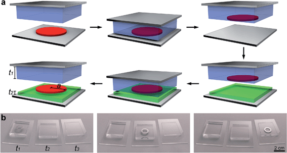
The concept of substrate thickness controlled adhesive transfer is presented in Fig. 1a. Initially, a solid object with lateral dimensions a is placed on a donor substrate and a planar elastomeric substrate of thickness, t1, on a rigid support is brought into conformal contact with the object. The substrate is lifted, the object is retrieved, and then the object is brought into contact with a second, thinner elastomeric substrate with a thickness t2 such that t2 < t1. The thinner substrate is then separated from the thicker substrate in the normal direction and the object is selectively transferred to the thinner substrate. This process is experimentally demonstrated in Fig. 1b and Movie S1† where a metallic washer is transferred to progressively thinner elastomeric substrates multiple times. This process is controlled by the geometric confinement of the interface defined by the ratio of the lateral length of the solid object to the thickness of the elastomeric substrate, a/t. As the confinement of the interface increases, the thinner elastomeric layer minimizes strain energy relative to the thicker elastomeric layer; hence the driving force for separation, or the applied strain energy release rate for interfacial failure at the thinner substrate interface, is less than that for the thicker substrate.25 Additionally, the thickness of the substrate for a given value of contact radius greatly influences the distribution of normal stress under the object.26 For thicker substrates, the stress is more concentrated on the contact edges; while for substrates in the infinitely thin limit, the maximum stress occurs in the center of contact. Both of these related changes, whether in terms of strain energy or stress distribution, physically determine the preference for the interface with the thicker substrate to release at a lower applied force, allowing the direction of transfer to be controlled. This technique does not rely on a specific microstructure, manipulation, or chemistry and thus provides a simple process to transfer an object.
To quantitatively describe the physics for this transfer mechanism we utilize our previously derived relationship for the adhesive force capacity, FC, of a rigid object of radius a attached to a compliant substrate of thickness t:
 | (1) |
To quantitatively confirm that the adhesive force capacity increases as substrate thickness is reduced in the transfer process, we perform contact adhesion experiments. These experiments are performed by brining a probe in contact with an elastomeric substrate and then retracting the probe normal to the surface until a maximum force FC is reached and the interface separates. By measuring FC of a punch on elastomeric substrates with decreasing thickness the driving force for adhesive transfer is confirmed. In our experiments, seven different punch radii are examined on four different substrate thicknesses. The results for these experiments are presented in Fig. 2a by plotting FC for the different punches as a function of substrate thickness. The data show that the adhesive force capacity depends on punch radii as well as substrate thickness. For a given substrate thickness, the force capacity increases by increasing the punch radii, and for a constant punch radii, the force capacity generally increases as substrate thickness is decreased. These results are compared with eqn (1) by plotting the normalized force capacity, FC/a3/2 as a function of the geometric confinement of the interface a/t in Fig. 2b. This figure demonstrates that the adhesive behavior is well-described by eqn (1) and that the geometric confinement of the interface controls the adhesive transfer mechanism demonstrated in Fig. 1. The data also show that changing the substrate thickness can provide a large enhancement in adhesive force capacity. Specifically, for the a = 3.17 mm probe we measured a 320% increase in pull-off force when going from an a/t confinement ratio of 0.6 to 8.7.
 | ||
| Fig. 2 Adhesive force capacity control through substrate thickness. (a) Force capacity versus thickness for a range of probe radii. (b) The data plotted in (a) on a linear-log plot of normalized force capacity versus the confinement of the interface, a/t, where the solid line represents eqn (1). (c) The driving force to transfer an object (FC2/FC1) versus the relative thickness ratio (t1/t2), where the lines represent eqn (4) for various initial confinement ratios (a/t)1. These plots quantitatively show that by decreasing the receiver thickness t2, the relative force capacity increases, causing the object to be transferred onto the receiver. | ||
The governing parameter for the transfer process is the ratio of the force capacity for the ‘inked’ compliant substrate, FC1, which contains the object(s), and the force capacity of the ‘receiver’ compliant substrate which receives the object(s), FC2. For an interface where both substrates are composed of the same material and the object to transfer has constant lateral dimensions:
 | (2) |
A dimensionless confinement ratio is defined:
 | (3) |
Upon substitution of eqn (2) and (3) into (1) we obtain:
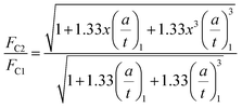 | (4) |
This normalized equation represents the driving force for the object to transfer, which is a function of the initial confinement (a/t)1 and the ratio of the inked and receiver substrate thicknesses, x. A plot of eqn (4) for a variety of initial confinement parameters as a function of x provides a visual design map for the transfer driving force, as seen in Fig. 2c. Eqn (4) and the design map in Fig. 2c consider that the strain energy in the system is primarily stored in the compliant substrates. This assumes that the objects are rigid relative to the compliant substrates. Therefore, for these predictions to hold for the transfer of soft objects, a stiffness mismatch is required. This could be accomplished by decreasing the stiffness of the compliant substrates to maintain a greater relative stiffness in the ink.
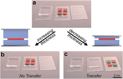
To demonstrate the robustness of this transfer process we show that transfer only occurs when moving objects to thinner, more highly confined interfaces. We start by placing glass squares (1 cm wide by 1 mm thick, colored red on one side) on a substrate such that the confinement ratio is a/t = 1.5 (Fig. 3b and Movie S2†). A stamp with a confinement ratio of a/t = 0.9 is then brought into contact with the array and upon separation the objects do not transfer (Fig. 3a). However, when a stamp with a greater confinement ratio of a/t = 4.2 is brought into contact, the entire array of objects is transferred (Fig. 3c, note color change of 2 glass squares indicates that all squares flipped to the other side upon transfer). By choosing the thickness of the compliant substrate the direction of transfer can be controlled.
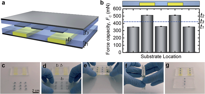
As the force capacity is sensitive to the degree of confinement it is possible to selectively retrieve objects by modulating the degree of confinement across a substrate. By patterning the underlying rigid support while maintaining a planar elastomer substrate, sub-surface patterns are created which spatially change the elastomer layer thickness and thus the confinement. A simple substrate is prepared (Fig. 4a) which consists of a rigid sub-surface step pattern, where the elastomer is thinner above the step, providing regions of higher confinement. Utilizing contact adhesion measurements (a = 2.59 mm) we measure force capacity across the patterned substrate and find that FC is varied in a step-wise manner such that it is maximum over the sub-surface steps and minimum in regions where sub-surface patterns are absent (Fig. 4b). To demonstrate the utility of this design as an adhesion controlled transfer process, we first pick up an array of 5 mm wide by 0.5 mm thick silicon wafers on an elastomer substrate which has a thickness intermediate to the two thickness regions on the patterned substrate (Fig. 4c and d and Movie S3†). This substrate is then brought into contact with the patterned substrate (Fig. 4e) and upon separation (Fig. 4f) the wafers that were over the sub-surface patterns were retrieved while the remaining objects were not transferred (Fig. 4g). Although this initial experiment consists of a simple sub-surface pattern, the methodology could be extended to a wide variety of more complex features.
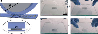
To extend this technique to high throughput methodologies we show how substrate thickness can enable a continuous roll-to-roll transfer process. As a proof of concept, a thick elastomer slab (t1 = 3.6 mm) is adhered to a rigid glass cylinder, and a thin elastomer layer (t2 = 0.37 mm) is adhered to a planar glass slide (Fig. 5a and Movie S4†). Silicon wafers (5 mm wide by 0.5 mm thick) are placed on a donor substrate (Fig. 5b). The cylinder is manually rolled over the wafers to retrieve them and then the cylinder with the wafers is rolled over the substrate with the thin elastomer, and all of the objects are transferred (Fig. 5c–e). This process is repeated over four cycles and all of the objects are transferred on each cycle. As the confinement of the interface, not kinetic effects, controls adhesion, the mechanism should be applicable as a high speed process.
Conclusions
We have demonstrated a transfer process controlled by substrate thickness, which does not require any specific actuations, chemistries, or surface topographies. Importantly, we have showed that the confinement of the interface is the controlling parameter for transfer and have described this through a physical model. It was shown that objects are transferred to substrates of increased confinement, and that transfer does not occur to substrates of lower confinement. We have also shown the ability of this process to selectively transfer objects based on position and to enable roll-to-roll, high throughput methodologies. As the controlling parameter is the confinement of the interface, the transfer process should be useful from macroscopic dimensions down to the micro/nanometer scale. Future work will explore transferred objects with different form factors, such as thin films and non-planar geometries. We anticipate that this simple transfer process will be useful in many applications, including unconventional material conveyance and manufacturing of flexible devices in electronics and biology, where precise placement of material components is required.Experimental
Material fabrication
Elastomeric substrates were made of polydimethylsiloxane (PDMS) (Dow Corning Sylgard 184) with an oligomer to curing agent ratio of 20![[thin space (1/6-em)]](https://www.rsc.org/images/entities/char_2009.gif) :
:![[thin space (1/6-em)]](https://www.rsc.org/images/entities/char_2009.gif) 1 by mass. Substrates with a thickness greater than 1 mm were fabricated by filling glass molds with uncured elastomer. The glass molds were made by fixing glass slides (Dow Corning) with cyanoacrylate adhesive (Loctite Super Glue) to a glass substrate. Before assembly, the glass was cleaned with soap and water, dried with air, cleaned with acetone, and dried again with air. Substrates less than 1 mm in thickness were made by spin coating. Patterned substrates were made by stacking glass slides together to a desired thickness, adhering them together, and then adhering the stack to a glass slide. A yellow film was added to the stack to provide imaging contrast. The elastomer was cured for 14 hours at 70 °C and then the glass molds were removed to expose the elastomer substrate.
1 by mass. Substrates with a thickness greater than 1 mm were fabricated by filling glass molds with uncured elastomer. The glass molds were made by fixing glass slides (Dow Corning) with cyanoacrylate adhesive (Loctite Super Glue) to a glass substrate. Before assembly, the glass was cleaned with soap and water, dried with air, cleaned with acetone, and dried again with air. Substrates less than 1 mm in thickness were made by spin coating. Patterned substrates were made by stacking glass slides together to a desired thickness, adhering them together, and then adhering the stack to a glass slide. A yellow film was added to the stack to provide imaging contrast. The elastomer was cured for 14 hours at 70 °C and then the glass molds were removed to expose the elastomer substrate.
Adhesion characterization
Transfer processes were performed manually such that conformal contact was achieved between the stamp and objects to be transferred and then the interface was separated while keeping the rigid substrates parallel. Adhesive force capacity measurements were made on the custom built contact adhesion instrument described previously.28 The adhesion experiments were performed by bringing a circular steel punch into contact with the PDMS substrate at a displacement rate of 10 μm s−1 and then retracted until complete separation occurred. Parallelism between the punch and substrates was maintained with a tilt and rotation platform (Newport) and force and displacement were continuously monitored and collected throughout the experiments with a custom computer program (National Instruments Labview). Seven different steel punches were utilized over a range from 0.17–3.83 mm and were each evaluated on four different substrate thicknesses 0.37, 1.2, 3.4, 5.3 mm. The 3.83 mm probe was not evaluated on the 0.37 mm thick substrate as the instrument stiffness was lower than the sample stiffness making it difficult to achieve conformal contact. Each experiment was cycled at the same location on the substrate five times and then analyzed with custom MATLAB code to measure adhesive force capacity.Acknowledgements
We acknowledge the University of Massachusetts research funds and the Human Frontiers Science Program for financial support of this research and S.A. Pendergraph for thoughtful discussions.Notes and references
- L. F. Boesel, C. Greiner, E. Arzt and A. Del Campo, Adv. Mater., 2010, 22, 2125–2137 CrossRef CAS PubMed.
- A. Carlson, A. M. Bowen, Y. Huang, R. G. Nuzzo and J. A. Rogers, Adv. Mater., 2012, 24, 5284–5318 CrossRef CAS PubMed.
- M. D. Bartlett, A. B. Croll, D. R. King, B. M. Paret, D. J. Irschick and A. J. Crosby, Adv. Mater., 2012, 24, 1078–1083 CrossRef CAS PubMed.
- H. E. Jeong, J.-K. Lee, H. N. Kim, S. H. Moon and K.-Y. Suh, Proc. Natl. Acad. Sci. U. S. A., 2009, 106, 5639–5644 CrossRef CAS PubMed.
- S. Reddy, E. Arzt and A. del Campo, Adv. Mater., 2007, 19, 3833–3837 CrossRef CAS.
- E. P. Chan, E. J. Smith, R. C. Hayward and A. J. Crosby, Adv. Mater., 2008, 20, 711–716 CrossRef CAS.
- C. S. Davis, D. Martina, C. Creton, A. Lindner and A. J. Crosby, Langmuir, 2012, 28, 14899–14908 CrossRef CAS PubMed.
- S. Y. Yang, A. Carlson, H. Cheng, Q. Yu, N. Ahmed, J. Wu, S. Kim, M. Sitti, P. M. Ferreira, Y. Huang and J. A. Rogers, Adv. Mater., 2012, 24, 2117–2122 CrossRef CAS PubMed.
- S. Kim, J. Wu, A. Carlson, S. H. Jin, A. Kovalsky, P. Glass, Z. Liu, N. Ahmed, S. L. Elgan, W. Chen, P. M. Ferreira, M. Sitti, Y. Huang and J. A. Rogers, Proc. Natl. Acad. Sci. U. S. A., 2010, 107, 17095–17100 CrossRef CAS PubMed.
- M. A. Meitl, Z.-T. Zhu, V. Kumar, K. J. Lee, X. Feng, Y. Y. Huang, I. Adesida, R. G. Nuzzo and J. A. Rogers, Nat. Mater., 2005, 5, 33–38 CrossRef.
- A. Carlson, H.-J. Kim-Lee, J. Wu, P. Elvikis, H. Cheng, A. Kovalsky, S. Elgan, Q. Yu, P. M. Ferreira, Y. Huang, K. T. Turner and J. A. Rogers, Appl. Phys. Lett., 2011, 98, 264104 CrossRef PubMed.
- Y. Mengüç, S. Y. Yang, S. Kim, J. A. Rogers and M. Sitti, Adv. Funct. Mater., 2012, 22, 1246–1254 CrossRef.
- A. G. Gillies, J. Kwak and R. S. Fearing, Adv. Funct. Mater., 2013, 23, 3256–3261 CrossRef CAS.
- A. Carlson, S. Wang, P. Elvikis, P. M. Ferreira, Y. Huang and J. A. Rogers, Adv. Funct. Mater., 2012, 22, 4476–4484 CrossRef CAS.
- V. Sariola and M. Sitti, Advanced Materials Interfaces, 2014 DOI:10.1002/admi.201300159.
- B. D. Kim, Y. Kim, J. Wu, Z. Liu, J. Song, H. Kim, Y. Y. Huang, K. Hwang and J. A. Rogers, Adv. Mater., 2009, 21, 3703–3707 CrossRef.
- E. Menard, L. Bilhaut, J. Zaumseil and J. A. Rogers, Langmuir, 2004, 20, 6871–6878 CrossRef CAS PubMed.
- Y. Sun and J. A. Rogers, Nano Lett., 2004, 4, 1953–1959 CrossRef CAS.
- K. J. Lee, M. J. Motala, M. A. Meitl, W. R. Childs, E. Menard, A. K. Shim, J. A. Rogers and R. G. Nuzzo, Adv. Mater., 2005, 17, 2332–2336 CrossRef CAS.
- A. J. Baca, M. A. Meitl, H. C. Ko, S. Mack, H.-S. Kim, J. Dong, P. M. Ferreira and J. A. Rogers, Adv. Funct. Mater., 2007, 17, 3051–3062 CrossRef CAS.
- B. K. Sharma, B. Jang, J. E. Lee, S.-H. Bae, T. W. Kim, H.-J. Lee, J.-H. Kim and J.-H. Ahn, Adv. Funct. Mater., 2012, 23, 2024–2032 CrossRef.
- J. Yoon, A. J. Baca, S.-I. Park, P. Elvikis, J. B. Geddes, L. Li, R. H. Kim, J. Xiao, S. Wang, T.-H. Kim, M. J. Motala, B. Y. Ahn, E. B. Duoss, J. A. Lewis, R. G. Nuzzo, P. M. Ferreira, Y. Huang, A. Rockett and J. A. Rogers, Nat. Mater., 2008, 7, 907–915 CrossRef CAS PubMed.
- T. Odom, J. Love, D. Wolfe, P. Kateri and G. M. Whitesides, Langmuir, 2002, 5314–5320 CrossRef CAS.
- M. D. Bartlett, A. B. Croll and A. J. Crosby, Adv. Funct. Mater., 2012, 22, 4985–4992 CrossRef CAS.
- A. J. Crosby and K. R. Shull, J. Polym. Sci., Part B: Polym. Phys., 1999, 37, 3455–3472 CrossRef CAS.
- K. R. Shull, C. Flanigan and A. J. Crosby, Phys. Rev. Lett., 2000, 84, 3057–3060 CrossRef CAS.
- M. D. Bartlett and A. J. Crosby, Langmuir, 2013, 29, 11022–11027 CrossRef CAS PubMed.
- D. R. Paretkar, M. D. Bartlett, R. McMeeking, A. J. Crosby and E. Arzt, J. Adhes., 2013, 89, 140–158 CrossRef CAS.
Footnote |
| † Electronic supplementary information (ESI) available: See DOI: 10.1039/c4mh00106k |
| This journal is © The Royal Society of Chemistry 2014 |

