 Open Access Article
Creative Commons Attribution 3.0 Unported Licence
Tools for chemical synthesis in microsystems
Klavs F.
Jensen
*,
Brandon J.
Reizman
and
Stephen G.
Newman
Department of Chemical Engineering, Massachusetts Institute of Technology, 77 Massachusetts Avenue, Cambridge MA 02139, USA. E-mail: kfjensen@mit.edu
First published on 28th May 2014
Abstract
Chemical synthesis in microsystems has evolved from simple proof-of-principle examples to become a general technique in academia and industry. Numerous such “flow chemistry” applications are now found in pharmaceutical and fine chemical synthesis. Much of the development has been based on systems employing macroscopic flow components and tubes, rather than the integrated chip technology envisioned by the lab-on-a-chip community. We review the major developments in systems for flow chemistry and discuss limitations underlying the development of chip-scale integrated systems.
Introduction
In the past two decades, chemical synthesis in microsystems has grown from textbook demonstration examples to a wide range of applications in pharmaceuticals and fine chemistry.1–10 This evolution has been driven by the inherent advantages of continuous flow in microsystems: controlled mixing, enhanced heat and mass transfer, and ease of integration. These characteristics enable safe operation of highly exothermic reactions and expand both the number of feasible reactions and the conditions over which they can be run. Moreover, continuous flow reduces accumulation of reactive or toxic intermediates and allows experimentation on well-defined samples at conditions not easily accessed by conventional means, such as reactions at high pressure and temperatures.2,4Small continuous flow systems for chemical synthesis are the basic tools for the rapidly expanding area of flow chemistry.1–10 Continuous manufacturing has been practiced for years at very large production scales in the petrochemical and commodity chemical industries. In the new flow chemistry efforts, organic chemists are taking advantage of the above features of continuous flow and replacing the traditional batch flask with tube systems to develop new reactions in sub-millimetre and larger systems. Examples of hazardous reactions performed with increased safety are highlighted in many recent reviews;1–10 such reactions include tetrazole formation, Strecker synthesis, phosgene chemistry, ozonolysis, and in situ production of diazomethane.2,4,10,11 The enhanced heat transfer rates have allowed safe operation of reactions with potential for thermal run-away, such as oxidations and fluorinations. Lithiations, among other fast reactions, have been implemented in flow and shown to give high yields and superior product distribution without the need for cryogenic conditions.10 Flow has also enabled utilization of reactions with unstable intermediates.12 Safe access to elevated pressures allows convenient superheating of solvents, giving enhanced rates and access to supercritical conditions, which, in addition to organic transformations, has been used advantageously in the synthesis of quantum dots.13 The advantages of photochemistry in flow (e.g., short exposure, short optical path, and wavelength filtering) have led to a renaissance in photochemical applications.14 Additionally, continuous flow has recently been demonstrated to greatly reduce the time to synthesize peptides.15
With many single transformations already implemented in flow, attention is increasingly shifting to multistep synthesis. Active pharmaceutical ingredients have been synthesized continuously by incorporating small-scale work up techniques or solid phase capture agents. These and other exciting developments in flow chemistry are summarized in several recent reviews. Herein, the focus is on the current state of microsystems for chemical synthesis, followed by a discussion of the challenges currently faced by the flow chemistry community and opportunities that would arise if these challenges were addressed.
Current state of microsystems for synthesis
Reaction components and systems
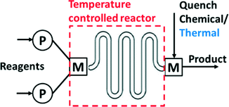
Several operations need to be integrated to perform synthesis in a microsystem (Fig. 1). These operations include pumping and metering of reactants, mixing, control of the reaction temperature, chemical and/or thermal quench, pressure control, and collection of product. Early efforts in the field used discrete components (pumps, reactors…) for flow synthesis,16 but commercial units now integrate all operations into compact units that require the user only to provide the reagents (Fig. 2). Nevertheless, many researchers still prefer the flexibility of combining isolated flow chemistry components for exploring a more diverse portfolio of chemical syntheses.1,5,7,10,17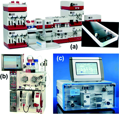 | ||
| Fig. 2 Examples of commercial systems using microreactors and tubes, (a) Syrris Africa system, (b) Vapourtec for general purpose flow chemistry, (c) ThalesNano H-Cube for catalytic hydrogenation. | ||
Integrated and component-based systems use either tubes or microstructured devices (microreactors) as reactor units. Tubes are most commonly made of either stainless steel or perfluorinated polymers. Alternatively, microreactors can be machined from glass, silicon-glass, ceramic, or stainless steel by microfabrication techniques (Fig. 3).16 Specialized units generate their own hazardous gas for gas–liquid reactions; for example the H-Cube (Fig. 2(c)) produces high purity hydrogen for high pressure hydrogenation reactions.
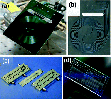 | ||
| Fig. 3 Examples of microstructured reactors in (a) silicon-Pyrex,20 (b) ceramics,21 (c) stainless steel (IMM),16 and (d) glass (Chemtrix).22 | ||
Tube-based systems are simple to operate and easy to create, but rely on diffusional mixing and are thus prone to dispersion effects. Perfluorinated tubes have the advantage of broad chemical compatibility, but suffer from poor heat transfer characteristics, which becomes an issue in running fast, highly exothermic reactions.11 The tube-in-tube reactor18 is convenient for gas–liquid reactions (e.g., hydrogenation). In this system a porous inner tube, typically made of Teflon AF, allows transport of a gas from one tube to a liquid flowing in the other.
Microreactors often include mixing units, flow distributors, multiple channels, and means for immobilizing catalyst particles.16 They typically also have the advantage of better heat transfer for heating and cooling reactions. In both tubes and microreactors, the effects of mixing and dispersion can be explored experimentally (e.g., by residence time distribution measurements) and predicted (from fluid dynamics simulations) to establish guidelines for running reactions under favourable mass and heat transfer conditions.11,16,19
Material compatibility issues have severely limited the realization of the integrated lab-on-a-chip vision of a small-scale, integrated synthesizer. In particular, on-chip integration has been limited by the difficulty of microfabricating chemically compatible, integrated valves and by pumping technologies. Hard materials such as silicon, glass, stainless steel, and ceramics are difficult to form into active valves whose actions are not easily blocked by small particles. Soft materials such as polydimethyl siloxane (PDMS) are easily formed into flexible structures, but are not chemically compatible. Perfluorinated materials would address the chemical compatibility issue, but they are difficult to bond into multilayered systems.
Flexible valve and peristaltic pump technologies in PDMS have allowed demonstration of integrated synthesizers for producing radiolabelled chemicals for Positron Emission Tomography (PET) (Fig. 4),23 but the PDMS devices were not sufficiently stable for safe, long time use. PET chemistry and other applications involving short-lived intermediates for health care are great opportunities for integrated chemical synthesis devices, but they require significant advances in on-chip pumping and valves for corrosive and particle laden flows.
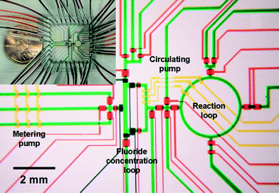 | ||
| Fig. 4 Example of integrated chemical synthesis on chip for the production of 2-deoxy-2-fluoro-D-glucose. The various channels have been loaded with food dyes to help visualize the different components of the microfluidic chip. Reprinted with permission from AAAS.23 | ||
Several commercial systems have been developed to enable scale-up of both single and multiphase flow chemistry procedures to production levels of tens of tons per year (Fig. 5).24,25 Simply multiplying microreactors to scale-out creates highly complex fluid flow distribution and control challenges. Consequently, scale-up is typically achieved by increasing reactor size while preserving heat and mass transfer advantages, and then by multiplying up the resulting smaller number of larger reactors. Good heat transfer characteristics are maintained by sandwiching a thin reaction layer between cooling plates and increasing the lateral size while keeping a nearly constant reactor channel depth (Fig. 5(a)). Mass transfer is kept high by multiplying out static mixer units rather than changing the size of the mixing units (Fig. 5(b)). A similar, tube-based approach is to scale to larger tubes filled with static mixing elements that increase mixing across the tube and reduce dispersion. The use of static mixers sets minimum flow velocities to achieve sufficient mixing across the tube to reduce dispersion.
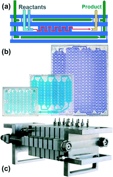 | ||
| Fig. 5 Examples of commercial flow reactor systems for production. (a, b) Corning Advanced Flow Reactors (AFR);24 (b) glass reactor plates of increasing size. Note the size of the static mixer structures remain similar with scaling of the plates. (Corning) (c) Lonza flow plate technology25 in stainless steel. (Ehrfeld Mikrotechnik-BST). | ||
As to the other equipment necessary to run continuous synthesis, a wide range of syringe and high performance liquid chromatography (HPLC) pumps are available, but developing reliable pumps for highly oxidizing, corrosive, and particle laden reagents remains an issue. Seals around syringe plungers and check valves in HPLC pumps are particularly prone to problems over long operating times. The cost of flow metering is also amplified when requiring chemical compatibility; such cost is an important consideration when pumps other than syringe pumps are used. Back pressure regulators (BPRs) are critical elements in enabling operation at elevated pressures and temperatures to enhance reaction rates and avoid the formation of gas bubbles. Many of the springs in conventional BPRs are easily corroded. Diaphragm-based BPRs with perfluorinated or Hastelloy materials in contact with the fluid streams circumvent these problems, but typically at higher costs.
Workup components
Workup processes such as liquid–liquid extraction and distillation are needed to perform multistep reactions. Conventional gravity based liquid–liquid separation has been automated and achieved at reduced sizes,26 but as units become smaller, surface tension forces dominate over gravity. It then becomes more efficient to use membrane separators that exploit surface tension differences between the aqueous and organic phases to achieve complete separation.27 Alternatively, side-by-side contact of phases in microfluidic systems has been employed in extractions, but with a lower throughput more suited for analytical applications.28Quantitative separation of gases and liquids can also be achieved with capillary membrane separators. In this case the liquid filled pores transport the liquid phase, blocking the passage of the gas so that it remains in the flow channel. This principle can be used to separate volatile solvents, serving as a single distillation stage.29Fig. 6 illustrates the combined use of liquid–liquid extraction and vapour–liquid separation in a two-stage reaction involving the formation of an aryl triflate followed by a Pd catalysed Heck reaction.30 After the first reaction step, the base is removed with an acidic wash in a Teflon membrane separator, and the organic phase containing the aryl triflate intermediate is recovered. Low boiling dichloromethane is then replaced by higher boiling DMF or toluene in the subsequent single distillation step prior to the Heck reaction. This solvent switch was needed to achieve good yield in the second reaction.
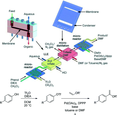 | ||
| Fig. 6 Multistep reaction sequence with liquid–liquid extraction and single stage distillation for solvent switch.30 | ||
In addition to membrane separators, falling film evaporators, distillation on chip, and miniaturized distillation columns31 have been demonstrated,32 but the techniques have yet to find wide spread application in multistep synthesis. Solid phase capturing agents and reactants have proven particularly effective tools in multistep synthesis of pharmaceutical compounds.5,33
Analysis and automation
Integration of on-line measurements of reactant flows, reactor temperature, and outlet concentrations with feedback control systems opens the opportunity for automated optimization of yield as well as finding kinetic information for subsequent scaling of the process. Such automated systems have the potential to save considerable time and materials in the development of new processes. Regulation of flows is easily and accurately accomplished with syringe pumps. Similarly the measurement of temperatures by thermocouples is straightforward.Determining concentrations of reactants and products is the primary analytical challenge to creating an automated reaction set-up. On-line Fourier transform infrared spectrometers based on attenuated total reflection sampling are well-suited for microreactor applications with microliter sample volumes,34,35 but spectral overlap complicates the technique for complex organic reactions. For reactions yielding many structurally similar products, on-line HPLC sampling is the most general technique; however, the cycle time of the HPLC typically ends up determining the how quickly the optimization can be performed. Analysis is predominantly done with off-line, separate units. On-chip integration of measurements has been limited by the same materials compatibility issues that have prevented integration of flow control.
‘Black-box’ optimization with the above systems requires little knowledge of the reaction and is suitable when the goal is to evaluate a specific metric, such as maximizing the product yield, and to subsequently scale the reactor size.35 Automated microreactor platforms can also be used to obtain knowledge of the reaction mechanism and kinetics.36,37 This information can be combined with fluid flow and heat transfer models to predict performance of scaled-up flow reactor systems. Automated systems can also be used to generate batch-like reaction time courses for kinetics studies of reactions that would be difficult to study in batch directly.38 Microreactors with built-in mixing units have typically been preferred in optimization studies over simple tube systems because of their well-controlled mixing and faster thermal response.
Automated optimization has so far been applied primarily to single step reactions with respect to process parameters that can be varied continuously over a range of conditions, such as temperature, pressure, flow rate, and concentration. Techniques from the chemical process literature suggest extension to multistep reactions would be feasible for these variables. Including discrete variables (e.g., catalyst, ligand, and solvent choices) presents challenges for both the experimental set-up and the selection of optimization algorithms. Further developments that include discrete variables would increase the generality of current process optimization techniques.
Use of segmented flow, in which the reaction medium is dispersed as individual drops in an inert phase, is one possible approach to address the challenge of optimizing over discrete variables. Automated liquid dispensing systems can be used to create liquid droplets of different compositions which are transported through a tube like a conveyor belt of individual batch reactors. Though droplet methods have been used before to screen39 and to generate libraries of compounds,40 they have yet to be coupled with on-line sampling and nonlinear, mixed integer software optimization to give a tool capable of rapidly and automatically optimizing for all variables—continuous and discrete—of interest to a synthetic chemist.
As a first example of catalyst optimization with segmented flow, Kreutz et al.41 employed a tube-in-tube reactor (Teflon within stainless steel) to find new homogeneous catalysts for the oxidation of methane by molecular oxygen. Catalyst, co-catalyst, and ligands were optimized using a genetic algorithm approach. The pressurized methane–oxygen mixture diffused through the gas-permeable Teflon tubing and into the catalyst plugs dispersed in perfluorinated oil (Fig. 7). Methanol formed in the presence of the catalysts and subsequently diffused through the fluorocarbon continuous phase to the neighbouring indicator plug, in which a colour change occurred depending on the amount of methanol produced, i.e., the catalytic activity.
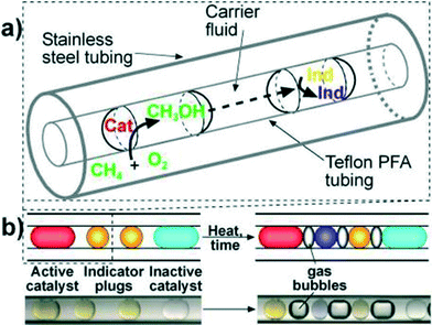 | ||
| Fig. 7 (a) Schematic of a section of Teflon tubing containing droplets inside stainless steel tubing. (b) Schematics (above) and microphotographs (below) show two indicator plugs separating adjacent catalyst plugs to enable clear identification of active catalysts.41 | ||
This elegant example demonstrates the power of the microfluidic technique, along with many of the difficulties associated with making droplet-based optimization generally applicable to organic transformations. Experimental challenges to be overcome include identifying a generalized analytical method such as online HPLC sampling and minimizing reagent carry-over between successive droplets. The use of fluorinated fluids works well with aqueous droplets and organics at low temperature, but common solvents such as alkanes, ethers, and light aromatics become increasingly soluble in fluorocarbons as temperature increases.
Challenges
The flow chemistry community has already reviewed challenges to the widespread use of flow for chemical synthesis, including development of a continuous-flow reaction toolbox and strategies for multistep synthesis.6,7 In the section on reactors and components, we emphasized difficulties in finding chemically compatible materials that could be machined into flow chemistry components. Challenges and opportunities for expanded reaction optimization including discrete process variables (e.g., catalyst, ligand, and solvent choices) were also discussed in the previous section. The following sections consider the general challenges of solids handling, catalyst recycling, reaction workup, and integration for future applications of microsystems for chemical synthesis.Handling of solids
The foremost challenge to implementing reactions in microsystems remains the handling of solids, which can lead to clogging of flow reactors. This problem is accentuated for sub-millimetre tube sizes.42 Reactions can sometimes be designed to minimize the risk of solids forming, but the unintentional presence of moisture can be a source of particle formation (e.g., in systems with strong bases, such as n-BuLi). Even small amounts of solids create problems by plugging check valves in pumps and BPRs. Moreover, solids are often products of reactions. For example, stoichiometric amounts of salt form in Buchwald–Hartwig cross-coupling amination reactions.Solid formation along the walls of a flow reactor causes an increase in pressure drop, which ultimately leads to breakup of the solid plug or complete clogging of the flow path. This situation can be mitigated by choosing reactor surfaces that do not promote solid nucleation, such as smooth perfluorinated surfaces. Periodic flushing that dissolves any deposited solids is also possible; however, this approach complicates the setup, lowers the productivity, and increases the chance for cross contamination of the washing fluid (e.g. water to remove inorganic salts) and the reacting medium (anhydrous organic solvent).
Parallel microreactor systems with integrated sensors and automated control can help mitigate the downtime associated with clogging and reactor flushing by redirecting reactant streams into cleared reaction channels. While in general both the mechanical technology (e.g., valves and small-scale pressure transducers) and control methodologies already exist to build such pressure-swing devices, the added complexity of the setup and the risk of contamination have made such highly-integrated devices impractical to implement for laboratory-scale discovery or development applications. Larger-scale production—where the cost of replacing or cleaning damaged equipment far exceeds the cost of real-time control—stands to benefit more from parallelization, though the frequency of blockages decreases as scale increases.
Agglomeration of rapidly forming small solid particles is characteristic of salt forming reactions and the most common cause of plugged reaction tubes and channels. This can be mitigated in microsystems by including ultrasound transducers that drive nucleation of cavitations on the aggregates so that they disintegrate and the resulting smaller particles flow through the system.43,44 The acoustic input heats the system—even with careful temperature control—and the frequency of the ultrasound has to be empirically matched to the system for best performance. Sonication enables solid-forming reactions such as cross-couplings to be performed with short residence times.45 Even with the sonication, there is a relatively low limit to concentration of solids that can be flown as a suspension, and there are no general methods for feeding solid reagents on the microscale.
A general understanding and control of nucleation in continuous flow would not only allow us to run reactions forming solids, but also enable the implementation of nucleation as a purification technique. This advancement would also require development of efficient small-scale filtration techniques. Dielectricphoresis and centrifugal forces can be used to steer solids at low concentrations, but dense suspensions again become a challenge.
Catalyst retention and recycle
Large-scale continuous petrochemical processes use heterogeneous catalysts that remain in stream for long periods of time. In contrast, homogeneous catalysts are essential for many of the organic transformations of interest to pharmaceutical and fine chemicals manufacturing. The potential toxicity of the catalysts along with the high cost of precious metals and ligands provide strong motivation for the retention of these catalysts within the reactor system. The continuous, closed nature of flow systems makes them particularly effective at catalyst recycling; however most existing recycling methods are not sufficiently generalizable to broad classes of homogeneous catalysts. Immobilization of homogeneous catalysts is a long standing challenge. Linking of the ligand to a solid support often results in decreased catalytic activity and leaching of the metal centre into the flowing stream, especially for catalysts involving oxidation–reduction cycles. Moreover, many common polymeric supports often swell in solvents, plugging microsystems.Biphasic operation combined with efficient phase separation by the aforementioned membrane tools is possible when the catalyst and product are present in separate phases, but that is only the case for few fortuitous instances. For example, phenols can be removed by extraction with aqueous base in the Pd catalyzed hydroxylation of aryl halides. The catalyst remains in the organic phase, which is recycled in a continuous loop.46 One newer approach to recycling of catalysts is the use of organic solvent nanofiltration (OSN) membranes that separate larger molecules (∼200–1000 Da), such as complex catalysts, from smaller starting materials and products.47 These membranes are typically made from polyamide, polyimide, or PDMS materials and have been demonstrated in homogeneous catalyst recycling experiments in batch and flow.47,48 Ongoing efforts aim to improve the base stability of OSN membranes to enable applications in cross-coupling reactions.
Workup techniques for microsystems
The need to synthesize molecularly complex products drives the need for multistep reactions with intermediate workup. The already-mentioned liquid–liquid membrane separators have proven effective in many applications, but evaporators are still needed to concentrate solutions and facilitate solvent switches. There are only a few examples of miniaturized distillation processes, and these methods need to be demonstrated in multistep reactions. As mentioned in connection with solids handling, it would be useful to have continuous crystal nucleation and filtration as intermediate and final purification tools. All of these workup techniques would have to be developed so that they can be used interchangeably in a plug-and-play fashion and also need to be matched to reaction equipment in terms of residence time and liquid hold-ups. Moreover, newly-developed workup techniques have to be fully characterized and easy to use so that a chemist can readily incorporate them into a reaction sequence.Flow components and integration
Stable operation of pumps, flow meters, and pressure controllers remains a challenge even at millilitres per minute flow rates. Corrosion of seals and springs combined with accumulation of solids in check valves underlie many of flow chemistry failures. These problems will have to be addressed by equipment vendors for the technology to be useful in process development. The flow and distribution problems are magnified at the microsystem level. Although there are potential opportunities for small-scale units for chemical synthesis and formulation, as of yet there are no broadly chemically resistant pumps beyond syringe pumps and no automated valve technologies for on-chip applications. Though it is possible to seal microreactors into larger units, a chemically resistant backplane technology is still needed that would enable the user to easily plug-in and reconfigure reactors and workup units for different chemical applications.Outlook
Flow chemistry applications have already expanded tremendously in the past decade and will continue to evolve as chemists add to the tool-box. Commercial units exist at both the lab and production scale, and the techniques are used in both academic and industry laboratories. Moreover, many chemists are becoming comfortable with creating tube systems for their experiments rather than starting with a flask. As flow equipment becomes increasingly common, it is likely that new reactions only feasible in flow will be discovered. Automated units that can optimize individual or multiple reaction steps as well as automatically explore the scope of a reaction are also likely to be a part of future chemistry laboratories.Integrated chemical microsystems are most likely to find applications in (i) automated optimization of reactions, catalysts, and solvents; (ii) target library generation and integration with biological microfluidic testing platforms; and (iii) small-scale production and formulations for diagnostics, such as PET chemistry, and for personalized therapeutics. Moreover, integrated biological and chemical systems could be envisioned as tools to produce new, precisely-controlled conjugates. All of these exciting promises do require, however, that we succeed in addressing the challenges outlined above.
Notes and references
- I. R. Baxendale, J. Chem. Technol. Biotechnol., 2013, 88, 519–552 CrossRef CAS.
- V. Hessel, D. Kralisch, N. Kockmann, T. Noel and Q. Wang, ChemSusChem, 2013, 6, 746–789 CrossRef CAS PubMed.
- L. Malet-Sanz and F. Susanne, J. Med. Chem., 2012, 55, 4062–4098 CrossRef CAS PubMed.
- S. G. Newman and K. F. Jensen, Green Chem., 2013, 15, 1456–1472 RSC.
- J. C. Pastre, D. L. Browne and S. V. Ley, Chem. Soc. Rev., 2013, 42, 8849–8869 RSC.
- J. Wegner, S. Ceylan and A. Kirschning, Chem. Commun., 2011, 47, 4583–4592 RSC.
- J. Wegner, S. Ceylan and A. Kirschning, Adv. Synth. Catal., 2012, 354, 17–57 CrossRef CAS.
- C. Wiles and P. Watts, Chem. Commun., 2011, 47, 6512–6535 RSC.
- J.-I. Yoshida, H. Kim and A. Nagaki, ChemSusChem, 2011, 4, 331–340 CrossRef CAS PubMed.
- J.-I. Yoshida, Y. Takahashi and A. Nagaki, Chem. Commun., 2013, 49, 9896–9904 RSC.
- R. L. Hartman, J. P. McMullen and K. F. Jensen, Angew. Chem., Int. Ed., 2011, 50, 7502–7519 CrossRef CAS PubMed.
- A. Nagaki, C. Matsuo, S. Kim, K. Saito, A. Miyazaki and J.-I. Yoshida, Angew. Chem., Int. Ed., 2012, 51, 3245–3248 CrossRef CAS PubMed.
- S. Marre and K. F. Jensen, Chem. Soc. Rev., 2010, 39, 1183–1202 RSC.
- J. P. Knowles, L. D. Elliott and K. I. Booker-Milburn, Beilstein J. Org. Chem., 2012, 8, 2025–2052 CrossRef CAS PubMed.
- M. D. Simon, P. L. Heider, A. Adamo, A. A. Vinogradov, S. K. Mong, X. Li, T. Berger, R. L. Policarpo, C. Zhang, Y. Zou, X. Liao, A. M. Spokoyny, K. F. Jensen and B. L. Pentelute, ChemBioChem, 2014, 15, 713–720 CrossRef CAS PubMed.
- Handbook of Micro Process Technology (Volume 1–3), ed. V. Hessel, A. Renken, J. C. Schouten and J. I. Yoshida, Wiley-VCH, Weinheim, Germany, 2009 Search PubMed.
- D. Webb and T. F. Jamison, Chem. Sci., 2010, 1, 675–680 RSC.
- J. C. Pastre, D. L. Browne, M. O'Brien and S. V. Ley, Org. Process Res. Dev., 2013, 17, 1183–1191 CrossRef CAS.
- K. D. Nagy, B. Shen, T. F. Jamison and K. F. Jensen, Org. Process Res. Dev., 2012, 16, 976–981 CrossRef CAS.
- M. W. Bedore, N. Zaborenko, K. F. Jensen and T. F. Jamison, Org. Process Res. Dev., 2010, 14, 432–440 CrossRef CAS.
- S. G. Newman, L. Gu, C. Lesniak, G. Victor, F. Meschke, L. Abahmaneb and K. F. Jensen, Green Chem., 2014, 16, 176–180 RSC.
- C. Wiles and P. Watts, Micro Reaction Technology in Organic Synthesis, CRC Press, Boca Raton, FL, USA, 2011 Search PubMed.
- C. C. Lee, G. D. Sui, A. Elizarov, C. Y. J. Shu, Y. S. Shin, A. N. Dooley, J. Huang, A. Daridon, P. Wyatt, D. Stout, H. C. Kolb, O. N. Witte, N. Satyamurthy, J. R. Heath, M. E. Phelps, S. R. Quake and H. R. Tseng, Science, 2005, 310, 1793–1796 CrossRef CAS PubMed.
- G. S. Calabrese and S. Pissavini, AIChE J., 2011, 57, 828–834 CrossRef CAS.
- D. Roberge, Green Process. Synth., 2012, 1, 129 CAS.
- M. O'Brien, P. Koos, D. L. Browne and S. V. Ley, Org. Biomol. Chem., 2012, 10, 7031–7036 CAS.
- A. Adamo, P. L. Heider, N. Weeranoppanant and K. F. Jensen, Ind. Eng. Chem. Res., 2013, 52, 10802–10808 CrossRef CAS.
- A. Aota, M. Nonaka, A. Hibara and T. Kitamori, Angew. Chem., Int. Ed., 2007, 46, 878–880 CrossRef CAS PubMed.
- R. L. Hartman, H. R. Sahoo, B. C. Yen and K. F. Jensen, Lab Chip, 2009, 9, 1843–1849 RSC.
- R. L. Hartman, J. R. Naber, S. L. Buchwald and K. F. Jensen, Angew. Chem., Int. Ed., 2010, 49, 899–903 CrossRef CAS PubMed.
- A. Ziogas, V. Cominos, G. Kolb, H. J. Kost, B. Werner and V. Hessel, Chem. Eng. Technol., 2012, 35, 58–71 CrossRef CAS.
- K. F. Lam, E. Cao, E. Sorensen and A. Gavriilidis, Lab Chip, 2011, 11, 1311–1317 RSC.
- I. R. Baxendale and S. V. Ley, Curr. Org. Chem., 2005, 9, 1521–1534 CrossRef CAS.
- C. F. Carter, H. Lange, S. V. Ley, I. R. Baxendale, B. Wittkamp, J. G. Goode and N. L. Gaunt, Org. Process Res. Dev., 2010, 14, 393–404 CrossRef CAS.
- J. S. Moore and K. F. Jensen, Org. Process Res. Dev., 2012, 16, 1409–1415 CrossRef CAS.
- J. P. McMullen and K. F. Jensen, Org. Process Res. Dev., 2011, 15, 398–407 CrossRef CAS.
- B. J. Reizman and K. F. Jensen, Org. Process Res. Dev., 2012, 16, 1770–1782 CrossRef CAS.
- J. S. Moore and K. F. Jensen, Angew. Chem., Int. Ed., 2014, 53, 470–473 CrossRef CAS PubMed.
- T. Hatakeyama, D. L. Chen and R. F. Ismagilov, J. Am. Chem. Soc., 2006, 128, 2518–2519 CrossRef CAS PubMed.
- P. P. Lange, A. R. Bogdan and K. James, Adv. Synth. Catal., 2012, 354, 2373–2379 CrossRef CAS.
- J. E. Kreutz, A. Shukhaev, W. B. Du, S. Druskin, O. Daugulis and R. F. Ismagilov, J. Am. Chem. Soc., 2010, 132, 3128–3132 CrossRef CAS PubMed.
- R. L. Hartman, Org. Process Res. Dev., 2012, 16, 870–887 CrossRef CAS.
- R. L. Hartman, J. R. Naber, N. Zaborenko, S. L. Buchwald and K. F. Jensen, Org. Process Res. Dev., 2010, 14, 1347–1357 CrossRef CAS.
- S. Kuhn, T. Noel, L. Gu, P. L. Heider and K. F. Jensen, Lab Chip, 2011, 11, 2488–2492 RSC.
- T. Noël, S. Kuhn, A. J. Musacchio, K. F. Jensen and S. L. Buchwald, Angew. Chem., Int. Ed., 2011, 50, 5943–5946 CrossRef PubMed.
- P. F. Li, J. S. Moore and K. F. Jensen, ChemCatChem, 2013, 5, 1729–1733 CrossRef CAS.
- L. Peeva, J. D. Burgal, S. Vartak and A. G. Livingston, J. Catal., 2013, 306, 190–201 CrossRef CAS PubMed.
- A. Kajetanowicz, J. Czaban, G. R. Krishnan, M. Malinska, K. Wozniak, H. Siddique, L. G. Peeva, A. G. Livingston and K. Grela, ChemSusChem, 2013, 6, 182–192 CrossRef CAS PubMed.
| This journal is © The Royal Society of Chemistry 2014 |

