Electrocatalytic upgrading of model lignin monomers with earth abundant metal electrodes†
Chun Ho
Lam
a,
Christy B.
Lowe
a,
Zhenglong
Li
a,
Kelsey N.
Longe
a,
Jordan T.
Rayburn
a,
Michael A.
Caldwell
a,
Carly E.
Houdek
a,
Jack B.
Maguire
a,
Christopher M.
Saffron
bc,
Dennis J.
Miller
c and
James E.
Jackson
*a
aDept of Chemistry, Michigan State University, East Lansing, MI 48824, USA. E-mail: jackson@chemistry.msu.edu
bDept of Biosystems & Agricultural Engineering, Michigan State University, East Lansing, MI 48824, USA
cDept of Chemical Engineering, Michigan State University, East Lansing, MI 48824, USA
First published on 3rd November 2014
Abstract
Guaiacol (2-methoxyphenol) and related lignin model monomers undergo electrocatalytic hydrogenolysis/hydrogenation (ECH) to cyclohexanol with RANEY® Nickel electrodes in aqueous solution. Aryl ether (C–O) bond cleavage is followed by reduction of the aromatic ring at ambient pressure and 75 °C. Related arene-OR cleavages occur at similar rates regardless of R-group size. Protons are supplied by anodic water oxidation on a stainless steel grid coated with cobalt-phosphate catalyst, inexpensively replacing the conventional platinum anode, and remaining viable in constant current electrolyses of up to 16 hours. The overall method addresses two key barriers to energy upgrading of low specific energy biomass into fuels and chemicals: deoxygenation and hydrogenation. By directly and simply coupling energy from renewable electricity into the chemical fuel cycle, ECH bypasses the complexity, capital costs and challenging conditions of classical H2 hydrotreating, and may help open the door to truly carbon-retentive displacement of fossil petroleum by renewables.
Introduction
With their high specific energies,1 low toxicity, and ease of handling, hydrocarbons hold a privileged place in the world's energy economies, both human and biospheric. It is no accident that mobile organisms use hydrocarbon-like fats and oils as their portable energy storage materials, whether they are warm- or cold-blooded, vertebrate or in-; aquatic, terrestrial or airborne. But human combustion of hydrocarbon fuels today consumes finite petroleum reserves while annually releasing over 31 gigatonnes of CO2 (2011 data), a bit over 1/3 of anthropogenic fossil CO2 injection into the atmosphere worldwide.2 Clearly, these essential fuels must eventually come from carbon-neutral renewable sources.In principle, biomass can serve as a feedstock from which to build renewable hydrocarbon fuels. But despite recent years’ huge investments in biomass-to-fuel conversions, a fundamental limitation exists: in the US, the simple thermochemical energy content of potentially available biomass is much smaller (less than 1/2) than the energy content of petroleum used.3 Most biofuel schemes simply concentrate the dilute energy content of biomass into a fraction of the matter, throwing away a significant portion of the carbon. For instance, the classic strategy, fermentation of glucose to ethanol, disposes of 1/3 of the carbon as “molecular ashes” (CO2) and makes a fuel with less than 2/3 the specific energy of hydrocarbons. High temperature gasification/shift reaction/Fischer–Tropsch diesel fuel synthesis (eqn (2)–(4)) similarly discards at least 1/3 of the carbon input due to the CO shifting required to raise the intrinsic 1![[thin space (1/6-em)]](https://www.rsc.org/images/entities/char_2009.gif) :
:![[thin space (1/6-em)]](https://www.rsc.org/images/entities/char_2009.gif) 1 H2
1 H2![[thin space (1/6-em)]](https://www.rsc.org/images/entities/char_2009.gif) :
:![[thin space (1/6-em)]](https://www.rsc.org/images/entities/char_2009.gif) CO ratio in carbohydrates to the 2
CO ratio in carbohydrates to the 2![[thin space (1/6-em)]](https://www.rsc.org/images/entities/char_2009.gif) :
:![[thin space (1/6-em)]](https://www.rsc.org/images/entities/char_2009.gif) 1 ratio needed for synthesis gas. Both these processes have high energy demands (mainly process heat), but little or none of that energy actually ends up in the product as fuel value.
1 ratio needed for synthesis gas. Both these processes have high energy demands (mainly process heat), but little or none of that energy actually ends up in the product as fuel value.
| C6H12O6 → 2CH3CH2OH + 2CO2 | (1) |
| C6H12O6 → 6CO + 6H2 | (2) |
| 2CO + 2H2O → 2H2 + 2CO2 | (3) |
| 4CO + 8H2 → 4“CH2” (alkane) + 4H2O | (4) |
To make biomass chemically tractable, a rapid, energy efficient liquefaction method is needed. Fast pyrolysis (4–600 °C for a few seconds) breaks biomass down into a complex mixture of molecular fragments. Depending on pyrolysis conditions and biomass pretreatments, the liquid “bio-oil” product can be formed in yields of up to 70%, with gases and char accounting roughly equally for the other 30%. This liquid comprises a complex mix of sugar and sugar ester fragmentation and dehydration products (e.g. acetic acid, hydroxyacetaldehyde, hydroxyacetone furfural, hydroxymethylfurfural, levoglucosan), along with phenolic lignin subunits (e.g. guaiacol, syringol, eugenol). Unfortunately, compared to gasoline, raw bio-oil is unusable as a transportation fuel, due to its high reactivity, acidity (ca. pH 2–3), and water content. With an oxygen![[thin space (1/6-em)]](https://www.rsc.org/images/entities/char_2009.gif) :
:![[thin space (1/6-em)]](https://www.rsc.org/images/entities/char_2009.gif) carbon ratio like that of plant material (roughly 1
carbon ratio like that of plant material (roughly 1![[thin space (1/6-em)]](https://www.rsc.org/images/entities/char_2009.gif) :
:![[thin space (1/6-em)]](https://www.rsc.org/images/entities/char_2009.gif) 1), bio-oil's specific energy, like that of biomass itself, is only ca. 1/3 that of hydrocarbons (15 vs. 45 MJ kg−1).4,5 Bio-oil's high content of reactive acid, carbonyl and phenolic compounds make it prone to polymerization on standing,6 and heating during conventional hydrodeoxygenation upgrading can accelerate this process.7 Though mainly carbohydrate (cellulose/hemicellulose), biomass contains as much as 20–30% lignin-derived phenolics, which are fragmented by fast pyrolysis into oxygenated aromatics8,9 whose carbon numbers fall in the range desirable for hydrocarbon fuels. Converting such starting materials into fuel-range products requires deoxygenation and hydrogenation to raise C
1), bio-oil's specific energy, like that of biomass itself, is only ca. 1/3 that of hydrocarbons (15 vs. 45 MJ kg−1).4,5 Bio-oil's high content of reactive acid, carbonyl and phenolic compounds make it prone to polymerization on standing,6 and heating during conventional hydrodeoxygenation upgrading can accelerate this process.7 Though mainly carbohydrate (cellulose/hemicellulose), biomass contains as much as 20–30% lignin-derived phenolics, which are fragmented by fast pyrolysis into oxygenated aromatics8,9 whose carbon numbers fall in the range desirable for hydrocarbon fuels. Converting such starting materials into fuel-range products requires deoxygenation and hydrogenation to raise C![[thin space (1/6-em)]](https://www.rsc.org/images/entities/char_2009.gif) :
:![[thin space (1/6-em)]](https://www.rsc.org/images/entities/char_2009.gif) O and H
O and H![[thin space (1/6-em)]](https://www.rsc.org/images/entities/char_2009.gif) :
:![[thin space (1/6-em)]](https://www.rsc.org/images/entities/char_2009.gif) C ratios, and thus also to raise the specific energy content, while retaining carbon.
C ratios, and thus also to raise the specific energy content, while retaining carbon.
Much effort has focused on petroleum refinery-style high temperature hydrodeoxygenation of biomass-derived feedstocks with hydrogen and solid upgrading catalysts.10–15 Various reviews have discussed production of hydrocarbon mixtures from model substrates or authentic bio-oils via classical heterogeneous catalytic hydrogenation/hydrogenolysis,16–20 including attempts with inexpensive catalysts such as RANEY® Nickel (Ra-Ni).21 Reductive lignin cleavages by purpose-built homogeneous nickel catalysts with various reductants have also been reported.22–25 However, the conventional reductant, molecular H2, is derived from natural gas or petroleum refining in today's markets, so despite its lack of carbon, it must be viewed as a fossil resource. An interesting transition metal-free alkoxy cleavage system makes use of organosilane but requires stoichiometric amounts of reagent and strong base which limits its potential for scale-up.26 Electrolytic hydrogen production from renewable electricity is becoming more practical, based on recent advances in water splitting catalysts. But ideally, protons and electrons from water splitting would be more directly used for liquid fuel hydrogenation in situ, bypassing the gas phase entirely. With this idea, herein we describe a simple strategy: electrocatalytic hydrogenation (ECH) as an approach towards energy and stability upgrading of the small-molecule fragments in biomass pyrolysis liquids to form chemicals and fuels.27,28
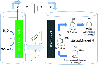
Compared to classical hydrogenation, ECH is a mild process, occurring at ambient pressures and below the boiling point of the electrolyte/co-solvent (in most cases water).29 Furthermore, because of the intrinsically heterogeneous nature of ECH, catalyst removal from the reaction mixture is a trivial physical step. As shown in Fig. 1, the effective source of hydrogen in ECH is the combination of protons from water splitting in the anode compartment with electrons at the surface of the catalytic cathode. The low cost, low overpotential cobalt phosphate catalyst introduced by the Nocera group,30–35 is used to effect water oxidation. This self-healing material is easily deposited on a stainless steel grid and operates for many hours with no signs of physical degradation or activity loss. Based on cobalt (30 ppm in earth's crust), a common by-product of copper and nickel refining,36 this catalyst is ∼3 orders of magnitude lower in cost than noble metals, an essential feature of any scheme considered for processes on the scale of the world's fuel industries.
RANEY® Nickel (Ra-Ni) is a well-known catalyst that is active and efficient for aromatic ring hydrogenation,37 It is also readily deposited on electrode surfaces via electroplating.38 Earlier studies found that Ra-Ni can cleave model lignin oligomers into smaller fragments and may further hydrogenate them, depending on conditions.39–41 In this work, we found that the primary reaction of alkoxyphenols is aryl–ether bond cleavage to form phenol, which is then hydrogenated to cyclohexanol, as shown in Fig. 1. The bond cleavage is relatively insensitive to the R-group size, but is affected by substitution position relative to the phenol –OH moiety.
Experimental
Preparation of the Ra-Ni cathode uses the Lessard method of trapping nickel–aluminum alloy particles in an electrodeposited nickel matrix.38,42 A square of stainless steel 314 screen (50 mesh, 2.5 × 2.5 cm) is submerged in 50 ml of nickel-ammonia plating solution (see ESI†) with 1.5 g of nickel-aluminum powder stirred in suspension. A nickel plate facing parallel to the mesh screen serves as the sacrificial anode. Plating current density, calculated in terms of the mesh side facing the anode, is maintained at 60 mA cm−2 for 2 hours. The electrode is turned 180° every 30 minutes to ensure even deposition on both sides. The plated electrodes are activated in a 75 °C NaOH (30% w/w) solution for 7 hours to etch out the aluminum. The activated electrodes are then stored in a 4% NaOH (w/w) solution for a minimum of 3 days before use.The water-splitting anode is prepared by placing a rolled up stainless steel 314 screen (8 mesh, 12 × 4 cm) in a beaker containing 200 ml of 0.10 M pH 7.0 potassium phosphate buffer and 0.50 mM Co(NO3)2 (i.e. 0.029 g of Co(NO3)2·6H2O added). With a stainless steel wire as a cathode, the deposition of the cobalt phosphate (Co-P) water oxidation catalyst is carried out for a minimum of 8 h at a current density of ca. 1.17 mA cm−2, the optimal value reported for catalyst formation.32
The two ECH electrodes are placed in a conventional divided cell separated by a Nafion 117 membrane. The Ra-Ni cathode is immersed in 30 ml of 0.1 M pH 8 potassium borate buffer. To increase solubility of the organic substrates and enhance cathodic surface activity, the cationic surfactant cetyltriethylammonium bromide (CTAB) is included in the catholyte at 0.5 mM, an optimal concentration determined in an exploratory survey (See ESI†).43–45 The Co-P-coated stainless steel mesh anode is in 30 ml of 0.1 M pH 7.0 potassium phosphate buffer. Temperature is set to 75 °C, and current to 50 mA (8 mA cm−2; note that current density is calculated based on electrode's single side facing the membrane and anode compartment.). After electrodes are equilibrated by pre-electrolysis for 60 min, substrate is added and subjected to ECH for 6 h.
Results and discussion
As shown in Table 1, when subjected to galvanostatic ECH, guaiacol undergoes methoxy group cleavage and hydrogenation to cyclohexanol. Only traces of 2-methoxycyclohexanol, the direct aromatic ring hydrogenation product, are seen; importantly, 2-methoxycyclohexanol does not react when explicitly subjected to the ECH conditions. This deoxygenation and structural simplification appear promising for bio-oil energy upgrading. Such aryl ether cleavages had been seen in earlier work by Lessard et al., but were not highlighted as unusual.46 However, organic chemistry's toolbox contains few simple methods for Ar–OR scission, so this clean, selective reaction is notable.| R group | Material balance (%) | *CE% | ||||
|---|---|---|---|---|---|---|
| a Product yields after 6 hours of electrolysis; values shown are percentages relative to starting material concentration, 12.1 ± 1.5 mM as determined by gas chromatography. Total current passed in this time represents 4× the amount required for substrate reduction to ROH and cyclohexanol. b Cis and trans products are in equal amounts. c Only a single peak was observed by GC. *CE% is calculated from the amount of product detected after 6 hours of electrolysis; see text for discussion. | ||||||
| 2-MeO | 1.1 | — | Tracesb | 79 | 80 | 26 |
| 2-EtO | 1.8 | — | — | 91 | 93 | 23 |
| 2-iPrO | 4.6 | 1.3 | — | 83 | 89 | 23 |
| 3-MeO | 9.9 | 0.6 | 32c | 41 | 84 | 18 |
| 4-MeO | Traces | Traces | 48b | 45 | 93 | 19 |
Quantum chemical simulations indicate that adsorption of phenol from vacuum onto a Ni catalyst prefers the aryl ring to lie flat on the metal surface.47,48 Such binding might be expected to suffer steric inhibition as sidechain bulk increases from methoxy to isopropoxy.49 However, ether alkyl group size has little effect on rate in our simple models, as seen in Fig. 2a, which shows ECH results for a mixture of guaiacol in competition with its congeners 2-ethoxy- and 2-isopropoxyphenol; all three are similar in reactivity.
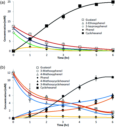 | ||
Fig. 2 (a) Time course for a 1![[thin space (1/6-em)]](https://www.rsc.org/images/entities/char_2009.gif) : :![[thin space (1/6-em)]](https://www.rsc.org/images/entities/char_2009.gif) 1 1![[thin space (1/6-em)]](https://www.rsc.org/images/entities/char_2009.gif) : :![[thin space (1/6-em)]](https://www.rsc.org/images/entities/char_2009.gif) 1 mixture of guaiacol, 2-ethoxyphenol, and 2-isopropoxyphenol undergoing electrocatalytic hydrogenation (ECH) under the conditions described in Table 1. All three reactants form phenol, which is further hydrogenated to cyclohexanol. Only traces of the alkoxycyclohexanols were detected. (b) Time course for a 1 1 mixture of guaiacol, 2-ethoxyphenol, and 2-isopropoxyphenol undergoing electrocatalytic hydrogenation (ECH) under the conditions described in Table 1. All three reactants form phenol, which is further hydrogenated to cyclohexanol. Only traces of the alkoxycyclohexanols were detected. (b) Time course for a 1![[thin space (1/6-em)]](https://www.rsc.org/images/entities/char_2009.gif) : :![[thin space (1/6-em)]](https://www.rsc.org/images/entities/char_2009.gif) 1 1![[thin space (1/6-em)]](https://www.rsc.org/images/entities/char_2009.gif) : :![[thin space (1/6-em)]](https://www.rsc.org/images/entities/char_2009.gif) 1 mixture of guaiacol, 3-methoxyphenol, and 4-methoxyphenol undergoing ECH as above. Direct arene hydrogenation products 3-methoxycyclohexanol and 4-methoxycyclohexanol are observed, together with major products phenol and cyclohexanol. Curves are polynomial fits included to guide the eye. 1 mixture of guaiacol, 3-methoxyphenol, and 4-methoxyphenol undergoing ECH as above. Direct arene hydrogenation products 3-methoxycyclohexanol and 4-methoxycyclohexanol are observed, together with major products phenol and cyclohexanol. Curves are polynomial fits included to guide the eye. | ||
Fig. 2b shows a similar competition, this time in ECH of 3- and 4-methoxyphenol (guaiacol isomers) under the above conditions. Cyclohexanol is the major product, but direct hydrogenation to 3- and 4-methoxycyclohexanol was observed (see Table 1) as well. Though the difference is modest, methoxy group retention is greatest in the 4-substituted case, suggesting that ether cleavage is favored by proximity to the phenolic hydroxyl group.
The current efficiencies (CE%) shown in Table 1 for each reaction were calculated as follows:
![[thin space (1/6-em)]](https://www.rsc.org/images/entities/char_2009.gif) 485 C mol−1, n = number of electrons per reaction, and Ctotal = total charge passed.
485 C mol−1, n = number of electrons per reaction, and Ctotal = total charge passed.
Though the CE% values in Table 1 do not capture the variations in instantaneous current efficiency (I-CE%) during reaction, they do give a comparative index as to how different compounds undergo ECH. The 2-alkoxyphenols’ CE% fluctuates around 23–26%, suggesting that alkoxy group size does not have a significant impact on the reaction. This conclusion is supported by the mixture trial shown in Fig. 2a. However, for the 3- and 4-methoxyphenols, the efficiency drops to 18–19%. The drop in selectivity to cyclohexanol and lower conversion suggest that the hydrogenation and demethoxylation of 3- and 4-methoxyphenol may be slightly less favorable, shifting reactions to favor H2 production.
Syringol (IUPAC name: 2,6-dimethoxyphenol) undergoes ether cleavage to produce guaiacol. However, as guaiacol reacts slower than phenol, so syringol is slower than guaiacol. Thus, as seen in Fig. 3, during reaction of syringol, concentrations of guaiacol and phenol remain low as the final product cyclohexanol accumulates. No 2,6-dimethoxycyclohexanols are seen, suggesting that ether hydrogenolysis is strongly preferred over aryl ether ring hydrogenation; presumably the more electron rich the arene, the more resistant it is to reduction. Fortunately, this preference for deoxygenation over saturation is exactly the reduction mode needed for optimal bio-mass pyrolysis liquid processing and energy upgrading.
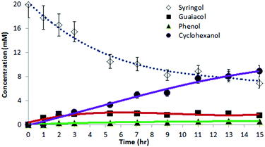 | ||
| Fig. 3 ECH of syringol (2,6-dimethoxyphenol) in 30 ml of 0.1 M pH 8 borate buffer with 0.5 mM CTAB at 75 °C. | ||
Catalysts beyond RANEY® Nickel
In further exploratory studies, RANEY® Cobalt (Ra-Co) and Devarda copper, skeletal metals other than Ra-Ni, were examined as cathodic catalysts. Cobalt–aluminum and copper–zinc–aluminum42 electrodes were prepared and activated using methods similar to those used for the Ra-Ni (see ESI†). Only Ra-Co formed observable traces of phenol and cyclohexanol after prolonged reaction times, as expected based on Ra-Co's known lower reactivity relative to Ra-Ni.37,50 Importantly, control experiments showed that a plain nickel bar electrode or a simple plated mesh without Ra-Ni embedded completely failed to reduce guaiacol or phenol. Together, these results indicate that both demethoxylation and hydrogenations require the highly active skeletal nickel surface.Material balance and current efficiency
As seen in Fig. 4a, cyclohexanol is produced at the expense of guaiacol. Once reaction begins, phenol is observable in small amounts throughout, suggesting that it is formed and liberated but undergoes hydrogenation faster than guaiacol conversion to phenol. In other words, the demethoxylation of guaiacol appears to be the slower, first step en route to cyclohexanol.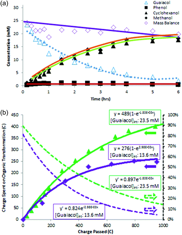 | ||
| Fig. 4 (a) Guaiacol, phenol, methanol, cyclohexanol, and material balance data from ECH at 8 mA cm−2 and 75 °C of 23.5 mM guaiacol in 30 ml of 0.1 M pH 8 potassium borate buffer; (b) Instantaneous current efficiency (I-CE%) analysis for the guaiacol reductions in 4a (23.5 mM) and in entry 1, Table 1 (13.6 mM). Charge spent on the organic transformation was plotted against charge passed, and the data were fitted to an exponential of form y = A(1 − e−kx) (solid lines). Differentiation of this function yielded the I-CE% curves plotted as dotted lines. | ||
Fig. 4a shows the reaction's material balance, with the sum of measured organics dropping slowly during the course of reaction. As discussed below, diffusion across the membrane and oxidative losses of phenols in the anode chamber may account for part of the observed material losses, along with adsorption on the cathode.
Two factors were considered to explain the deficits in material balance seen in Fig. 4a and also discernable in Fig. 3: adsorption on the cathode, and diffusion across the membrane. The initial prompt disappearance of guaiacol suggests its adsorption and retention in the porous Ra-Ni electrode. To assess adsorption capacity for phenol, the intermediate substrate, on the electrode surface, a new Ra-Ni electrode was immersed (5 min, no current passed) in 30 ml of electrolyte solution containing 296 μmol (9.85 mM) of phenol. It was then washed with clean borate buffer electrolyte for 5 min to clean off the excess non-adsorbed phenol. After the adsorption step, only 228 μmol (7.6 mM) remained in the original phenol electrolyte solution. Thus 69 μmol (2.3 mM) had been removed by the electrode. The clean buffer wash took up 33 μmol (1.1 mM), implying that 36 μmol (1.2 mM) of phenol must have remained adsorbed on the electrode surface. However, when the treated electrode was then used for electrolysis (100 min) in a clean 30 ml buffer solution, only yielding 1.6 μmol (0.053 mM) of phenol and 6.64 μmol (0.22 mM) of cyclohexanol were found in the solution. Since cyclohexanol appears not to adsorb at all, this result implies that a fraction of the adsorbed phenol was irreversibly bound on the surface, removing it from the mass balance.
A second loss mechanism is diffusion through the Nafion membrane separating cathode and anode compartments. Small amounts of cyclohexanol, which is neither strongly bound to Ra-Ni, nor oxidized on the Co-P anode, were detected in the anolyte. The phenols, also able to diffuse through the membrane, bring an additional vulnerability: they are oxidized by the Co-P water splitting catalyst. Though guaiacol and phenol were not detected in the anodic chamber under the usual cell conditions, these aromatics did appear in control experiments in which the cell chambers were assembled and left without current flowing. (see ESI†) When the cell was then polarized, the phenols in the anode chamber quickly disappeared, while a brown buildup was seen on the anode, consistent with the phenols’ oxidation and polymerization on the anode surface.51
A second control experiment was run the usual way (30 mL of 18 mM guaiacol at 75 °C) but used a plain nickel plate cathode, incapable of aromatic hydrogenation. After 5 hours of electrolysis, only about 14 mM of guaiacol remained in the catholyte, though no reduction products were detected by GC. A small amount of guaiacol (ca. 1 mM) was seen in the anode compartment early in the ECH run, but disappeared after the first hour (see ESI†), suggesting that guaiacol diffused across the membrane in the beginning and was then oxidized at the anode.
Instantaneous current efficiency (I-CE%) was assessed by plotting the charge (in coulombs) consumed in product formation versus the total amount of charge passed in the electrolysis as shown in Fig. 4b. Unlike the overall CE% equation shown above, this strategy can reveal variations in CE% during the course of reaction. Values for charge consumed in product formation were fitted to an exponential curve, and the resulting function was differentiated to obtain I-CE%, a measure of the fraction of current going to product formation at each point in the reaction. The dotted line I-CE% plots indicate theoretical initial I-CE% values of 90% and 82% for the 23.5 mM and 13.6 mM guaiacol ECH reactions, respectively. The I-CE% lines for both reactions decrease over the 6 hour reaction times. As guaiacol substrate is consumed, an increasing fraction of the current goes to formation of H2 gas. This sensitivity to reactant concentration suggests that even at the initial concentrations, surface sites are not saturated. Higher guaiacol concentrations (e.g. 50 mM) were therefore attempted but ran into solubility limits at the standard conditions applied in this work.
Mechanistic analyses
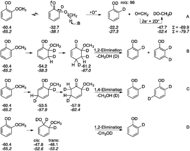
The demethoxylation of guaiacol under the mild conditions of aqueous electrolysis is a potential key to enable low-cost bio-oil's energy upgrading to useful chemicals and fuels. By analyzing the reaction paths involved in reaction of model compounds such as guaiacol, we hope to understand and develop some control over such processes, with the larger goal of extending these reactions to the general category of lignin-derived phenylpropanoid substrates found in bio-oil. We therefore have postulated several mechanistic schemes and devised experiments to distinguish among them.Spectroscopic study of adsorption on highly porous surfaces like the skeletal metals remains a challenge to present techniques. However, experimental and theoretical findings in the literature suggest that phenol and aniline both adsorb through the pi-ring interaction with the Ni (111) metal surface.47,48 This suggests that direct ether hydrogenolysis via a path involving oxidative insertion into the Ar–OR bond is unlikely.52 In our view, a more reasonable scenario is initial partial hydrogenation of the arene, followed by rearomatization via elimination. It is thus of interest to know which modes of H2 addition to the arene are most favorable. To probe this issue, quantum chemical calculations on the energetics of the various partially hydrogenated guaiacol isomers were performed, along with deuterium label incorporation studies. Pathways considered are summarized in Scheme 1.
Envisioning ECH as taking place by delivery of the elements of H2, Scheme 1 displays four candidate paths for the net hydrodemethoxylation of guaiacol. One hypothesis for methoxy group cleavage from guaiacol involves C–H activation at the methyl group, as shown in path A. This mechanism is ruled out by 1H-NMR of a reaction mixture run in D2O. The product mixture showed only methanol-H3, confirmed by sample spiking, with the singlet peak at 3.49 ppm in the product mixture; methanol-D1 would show a triplet due to H–D germinal coupling (see ESI†).53
In principle, analysis of the sites of deuteration in product phenol could provide insight into the demethoxylation process, potentially distinguishing among path B–D in Scheme 1. For instance, paths B and C should lead to di- and tri-deuterated phenol while D should result solely in di-deuterated phenol. However, under the reaction conditions, deuterium exchange into phenol (all sites) is rapid, and guaiacol also undergoes a couple of H/D exchanges.54 Thus, the phenol ring's record of reaction is erased by this rapid H/D exchange, yielding inconclusive results as to the mechanism of ether hydrogenolysis and subsequent phenol hydrogenation.
Some guidance may be gleaned from thermochemical insights. Scheme 1 summarizes comparisons of paths B–D in terms of the relevant intermediates’ heat of formation, calculated using the T1 and SM8 methods55b,c as implemented in the Spartan 14 program.55 These results suggest path B should be slightly preferred over C, with D significantly less favorable. Plain numbers below the species depicted in Scheme 1 represent gas-phase heats of formation, while the italicized values below reflect the further energy lowering via solvation in (theoretical) water as computed by the SM8 solvation model. Qualitatively, the solvation corrections do not change the overall energetic orders.
Besides the issue of ring reaction sites, does cyclohexanol form with or without release of the intermediate phenol? To probe this question, we examined the reaction in the presence of p-cresol as a phenol competitor. Competition experiments show that p-cresol and phenol are hydrogenated at essentially the same rate. If phenol is released, then p-cresol presumably would compete with it on an even footing for reduction sites. When 1![[thin space (1/6-em)]](https://www.rsc.org/images/entities/char_2009.gif) :
:![[thin space (1/6-em)]](https://www.rsc.org/images/entities/char_2009.gif) 1 and 1
1 and 1![[thin space (1/6-em)]](https://www.rsc.org/images/entities/char_2009.gif) :
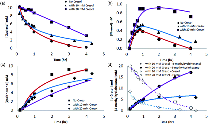
:![[thin space (1/6-em)]](https://www.rsc.org/images/entities/char_2009.gif) 2 ratios of guaiacol to p-cresol were subjected to ECH, guaiacol conversion was slowed (see Fig. 5a), the relative proportion of phenol in solution increased (see Fig. 5b), cyclohexanol formation was slowed (Fig. 5c), and 4-methylcyclohexanol was formed (Fig. 5d). These findings confirm that at least a substantial fraction of the phenol formed desorbs and equilibrates with bulk solution. The inhibition not only of phenol but also of guaiacol conversion by p-cresol suggests that demethoxylation and aromatic hydrogenation likely occur at the same catalytic sites. Given the rapid Ni-catalyzed H/D exchange seen in ECH of phenol in D2O, these sites appear able to bind and exchange hydrogen quickly with arenes without net reduction. It is for these reasons that we postulate a mechanism as in Scheme 1, where guaiacol adsorbs on an active site, is partially hydrogenated and then rearomatized via alcohol elimination. The resulting phenol then enters the equilibrating substrate pool in the bulk solution.
2 ratios of guaiacol to p-cresol were subjected to ECH, guaiacol conversion was slowed (see Fig. 5a), the relative proportion of phenol in solution increased (see Fig. 5b), cyclohexanol formation was slowed (Fig. 5c), and 4-methylcyclohexanol was formed (Fig. 5d). These findings confirm that at least a substantial fraction of the phenol formed desorbs and equilibrates with bulk solution. The inhibition not only of phenol but also of guaiacol conversion by p-cresol suggests that demethoxylation and aromatic hydrogenation likely occur at the same catalytic sites. Given the rapid Ni-catalyzed H/D exchange seen in ECH of phenol in D2O, these sites appear able to bind and exchange hydrogen quickly with arenes without net reduction. It is for these reasons that we postulate a mechanism as in Scheme 1, where guaiacol adsorbs on an active site, is partially hydrogenated and then rearomatized via alcohol elimination. The resulting phenol then enters the equilibrating substrate pool in the bulk solution.
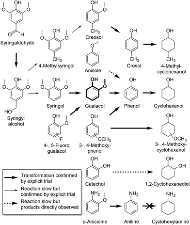
To further map the reactivity of the Ra-Ni electrocatalyst, we have extended our demethoxylation studies to other related substrates, shown in Scheme 2. Anisole does not undergo demethoxylation to benzene nor is it significantly hydrogenated to cyclohexyl methyl ether; instead it is slowly demethylated to phenol, which is then reduced to cyclohexanol. Interestingly, o-anisidine (IUPAC: 2-methoxyaniline) does undergo demethoxylation, though the nickel catalyst does not reduce the resulting aniline.56 Apparently the hydrogen-bond capable phenolic –OH or aniline –NH2 groups are crucial to the demethoxylation processes presented above. Syringaldehyde, when subjected to the demethoxylation conditions, exhibited a brown color, presumably due to polymerization. GC-MS analysis on the organic extractable content from this reaction revealed formation of syringyl alcohol, syringol, guaiacol, phenol, and cyclohexanol, as well as small amounts of their para methylated congeners. The base-promoted dehydroxymethylation that transforms syringyl alcohol to syringol is known (see ESI†).57 The behavior of catechol is somewhat puzzling; it only yields traces of phenol, favoring instead formation of the 1,2-cyclohexanediols. To see how an electron deficient ring would change the reactivity, 4- and 5-fluoroguaiacol were tested. Interestingly, however, only guaiacol was seen by the end of reaction, indicating that hydro-defluorination dominates the aromatic partial hydrogenation of these substrates.
Conclusion and outlook
We have described a mild electrocatalytic deoxygenation–hydrogenation process for reduction of lignin model compounds in a simple, low-cost system that avoids the use of precious metal or costly molecular catalysts. Remarkably, instead of arene reduction, the first event in ECH of alkoxyphenols or -anilines is the cleavage of the aryl–OR ether bond. The anode's cobalt-phosphate water oxidation catalyst selectively oxidizes water serving through the typical 6 hours reactions times, and the 16-hour syringol trial with no signs of degradation. Also, though Nafion is known to transport cations, no cobalt was detected by EDX on the used Ra-Ni cathode. On the other hand, the Ra-Ni cathodes were found to lose their catalytic hydrogenolysis activity over longer reaction runs. We will report on efforts to stabilize the Ra-Ni ECH electrodes in a separate publication. The current efficiency study indicates that reaction is sensitive to the surface concentration of reactant, as expected. Therefore, in parallel to the catalyst stabilization study, we are also pursuing a flow system in which hydrogenation can be achieved continuously by exposing the catalyst to reactant supplied at a constant concentration. These studies will be discussed in a future report.The conversion scheme proposed herein opens the door to a new way to maximize yields from biomass-based feedstocks via carbon-retentive energy upgrading using renewable electricity. In turn, it represents a strategy for buffering demand-mismatched production of solar or wind energy by storing it in a fungible chemical form. To optimize efficiency and working lifetime of the system, areas of ongoing development include improvements in cell design, energy and current efficiency, and cathodic electrocatalyst stability. The organic chemical transformations described here also have synthetic potential. Studies to probe selectivity and mechanism of the aryl ether cleavages, and to further extend the range of substrates are also underway.
Abbreviations
| Me | Methyl group |
| Et | Ethyl group |
| MeO | Methoxy group |
| EtO | Ethoxy group |
| iPrO | Isopropoxy group |
Acknowledgements
The authors acknowledge financial support from a Strategic Partnership Grant through Michigan State University (MSU-SPG). Authors C. Lowe, K. Longe, M. Caldwell, and C. Houdek thank MSU for support via Professorial Assistant fellowships. Author J. Maguire thanks University of Rochester for his undergraduate research travel support to MSU.Notes and references
- Specific energy = energy per unit mass. Hydrocarbon fuels such as gasoline and diesel typically have specific energies in the range of 42–48 MJ kg−1. For comparison, specific energies of dry biomass are roughly 12–18 MJ kg−1.
- Highlights: CO2 Emissions from Fuel Combustion”, International Energy Agency Statistics, 2013 Edition.
- M. Downing, L. M. Eaton, R. L. Graham, M. H. Langholtz, R. D. Perlack, A. F. Turhollow Jr., B. Stokes and C. C. Brandt, U.S. Billion-Ton Update: Biomass Supply for a Bioenergy and Bioproducts Industry, 2011 Search PubMed.
- D. C. Elliott, Energy Fuels, 2007, 21, 1792–1815 CrossRef CAS.
- P. M. Mortensen, J. D. Grunwaldt, P. A. Jensen, K. G. Knudsen and A. D. Jensen, Appl. Catal., A, 2011, 407, 1–19 CrossRef CAS.
- T.-S. Kim, J.-Y. Kim, K.-H. Kim, S. Lee, D. Choi, I.-G. Choi and J. W. Choi, J. Anal. Appl. Pyrolysis, 2012, 95, 118–125 CrossRef CAS.
- F. De Miguel Mercader, P. J. J. Koehorst, H. J. Heeres, S. R. A. Kersten and J. A. Hogendoorn, AIChE J., 2011, 57, 3160–3170 CrossRef CAS.
- M. M. Campbell and R. R. Sederoff, Plant Physiol., 1996, 110, 3–13 CAS.
- N. Mosier, C. Wyman, B. Dale, R. Elander, Y. Y. Lee, M. Holtzapple and M. Ladisch, Bioresour. Technol., 2005, 96, 673–686 CrossRef CAS PubMed.
- E. Furimsky, Appl. Catal., A, 2000, 199, 147–190 CrossRef CAS.
- S. Czernik and A. V. Bridgwater, Energy Fuels, 2004, 18, 590–598 CrossRef CAS.
- V. N. Bui, D. Laurenti, P. Afanasiev and C. Geantet, Appl. Catal., B, 2011, 101, 239–245 CrossRef CAS.
- R. C. Baliban, J. A. Elia and C. A. Floudas, Energy Environ. Sci., 2013, 6, 267–287 CAS.
- R. Rinaldi and F. Schuth, Energy Environ. Sci., 2009, 2, 610–626 CAS.
- J. C. Serrano-Ruiz and J. A. Dumesic, Energy Environ. Sci., 2011, 4, 83–99 CAS.
- C. Zhao, Y. Kou, A. A. Lemonidou, X. Li and J. A. Lercher, Angew. Chem., Int. Ed., 2009, 48, 3987–3990 CrossRef CAS PubMed.
- T. V. Choudhary and C. B. Phillips, Appl. Catal., A, 2011, 397, 1–12 CrossRef CAS.
- D. C. Elliott and T. R. Hart, Energy Fuels, 2008, 23, 631–637 CrossRef.
- J. Wildschut, F. H. Mahfud, R. H. Venderbosch and H. J. Heeres, Ind. Eng. Chem. Res., 2009, 48, 10324–10334 CrossRef CAS.
- A. V. Bridgwater, Biomass Bioenergy, 2012, 38, 68–94 CrossRef CAS.
- C. Zhao, Y. Kou, A. A. Lemonidou, X. Li and J. A. Lercher, Chem. Commun., 2010, 46, 412–414 RSC.
- A. G. Sergeev and J. F. Hartwig, Science, 2011, 332, 439–443 CrossRef CAS PubMed.
- P. Kelley, S. Lin, G. Edouard, M. W. Day and T. Agapie, J. Am. Chem. Soc., 2012, 134, 5480–5483 CrossRef CAS PubMed.
- M. Tobisu and N. Chatani, ChemCatChem, 2011, 3, 1410–1411 CrossRef CAS.
- A. G. Sergeev, J. D. Webb and J. F. Hartwig, J. Am. Chem. Soc., 2012, 134, 20226–20229 CrossRef CAS PubMed.
- A. Fedorov, A. A. Toutov, N. A. Swisher and R. H. Grubbs, Chem. Sci., 2013, 4, 1640–1645 RSC.
- Z. Li, M. Garedew, C. H. Lam, J. E. Jackson, D. J. Miller and C. M. Saffron, Green Chem., 2012, 14, 2540–2549 RSC.
- Z. L. Li, S. Kelkar, C. H. Lam, K. Luczek, J. E. Jackson, D. J. Miller and C. M. Saffron, Electrochim. Acta, 2012, 64, 87–93 CrossRef CAS.
- Electrocatalysis, ed. J. Lipkowski and P. Ross, Wiley-VCH, New York, 1998 Search PubMed.
- M. W. Kanan, Y. Surendranath and D. G. Nocera, Chem. Soc. Rev., 2009, 38, 109–114 RSC.
- D. A. Lutterman, Y. Surendranath and D. G. Nocera, J. Am. Chem. Soc., 2009, 131, 3838–3839 CrossRef CAS PubMed.
- M. W. Kanan and D. G. Nocera, Science, 2008, 321, 1072–1075 CrossRef CAS PubMed.
- A. J. Esswein, Y. Surendranath, S. Y. Reece and D. G. Nocera, Energy Environ. Sci., 2011, 4, 499–504 CAS.
- M. W. Kanan, J. Yano, Y. Surendranath, M. Dincă, V. K. Yachandra and D. G. Nocera, J. Am. Chem. Soc., 2010, 132, 13692–13701 CrossRef CAS PubMed.
- J. G. McAlpin, Y. Surendranath, M. Dincǎ, T. A. Stich, S. A. Stoian, W. H. Casey, D. G. Nocera and R. D. Britt, J. Am. Chem. Soc., 2010, 132, 6882–6883 CrossRef CAS PubMed.
- R. U. Ayres and L. T. Peiró, Philos. Trans. R. Soc. London, Ser. A, 2013, 371, 20110563 CrossRef PubMed.
- R. L. Augustine, Heterogeneous Catalysis for the Synthetic Chemist, Marvel Dekker, Inc., New York, 1995 Search PubMed.
- D. Robin, M. Comtois, A. Martel, R. Lemieux, A. K. Cheong, G. Belot and J. Lessard, Can. J. Chem., 1990, 68, 1218–1227 CrossRef CAS.
- A. Cyr, F. Chiltz, P. Jeanson, A. Martel, L. Brossard, J. Lessard and H. Ménard, Can. J. Chem., 2000, 78, 307–315 CrossRef CAS.
- D. Forchheim, U. Hornung, P. Kempe, A. Kruse and D. Steinbach, Int. J. Chem. Eng., 2012, 2012 Search PubMed.
- P. Dabo, A. Cyr, J. Lessard, L. Brossard and H. Ménard, Can. J. Chem., 1999, 77, 1225–1229 CAS.
- G. Belot, S. Desjardins and J. Lessard, Tetrahedron Lett., 1984, 25, 5347–5350 CrossRef CAS.
- H. Ilikti, N. Rekik and M. Thomalla, J. Appl. Electrochem., 2002, 32, 603–609 CrossRef CAS.
- H. Ilikti, N. Rekik and M. Thomalla, J. Appl. Electrochem., 2004, 34, 127–136 CrossRef CAS.
- P. Chambrion, L. Roger, J. Lessard, V. Béraud, J. Mailhot and M. Thomalla, Can. J. Chem., 1995, 73, 804–815 CrossRef CAS.
- A. Cyr, F. Chiltz, P. Jeanson, A. Martel, L. Brossard, J. Lessard and H. Ménard, Can. J. Chem., 2000, 78, 307–315 CrossRef CAS.
- L. Delle Site, A. Alavi and C. F. Abrams, Phys. Rev. B: Condens. Matter, 2003, 67, 193406 CrossRef.
- K. Kishi, K. Chinomi, Y. Inoue and S. Ikeda, J. Catal., 1979, 60, 228–240 CrossRef CAS.
- J. Lessard, in Encyclopedia of Applied Electrochemistry, ed. G. Kreysa, K.-i. Ota and R. Savinell, Springer, New York, 2014, pp. 443–448 Search PubMed.
- B. V. Aller, J. Appl. Chem., 1958, 8, 492–495 CrossRef CAS.
- L. Bao, R. Xiong and G. Wei, Electrochim. Acta, 2010, 55, 4030–4038 CrossRef CAS.
- However a recent review of homogeneous activation of A–OR bonds suggests classical oxidative insertion as the starting point. See: S. Z. Tasker, E. A. Standley and T. F. Jamison, Nature, 2014, 509, 299–309 CrossRef CAS PubMed.
- R. T. Wheelhouse and M. F. G. Stevens, J. Chem. Soc., Chem. Commun., 1993, 1177–1178 RSC.
- Deuterium contents of guaiacol, phenol, and cyclohexanol in a sample from ECH of guaiacol in D2O taken at 30 m reaction time were analyzed by 1H-NMR and GC-MS. Control experiments, where both guaiacol and phenol were independently heated to 75 °C for 6 hours in pH 10.5 borate buffer in the absence of RANEY nickel, showed no deuteration on the aromatic ring.
- (a) Spartan'14, Wavefunction, Inc., Irvine, CA Search PubMed; (b) T1 method: W. S. Ohlinger, P. E. Klunzinger, B. J. Deppmeier and W. J. Hehre, J. Phys. Chem. A, 2009, 113, 2165–2175 CrossRef CAS PubMed; (c) SM8 method: A. V. Marenich, R. M. Olson, C. P. Kelly, C. J. Cramer and D. G. Truhlar, J. Chem. Theory Comput., 2007, 3, 2011 CrossRef CAS.
- H. Adkins, H. I. Cramer and R. Connor, J. Am. Chem. Soc., 1931, 53, 1402–1405 CrossRef CAS.
- D. A. Smith and D. R. Dimmel, J. Wood Chem. Technol., 1994, 14, 297–313 CrossRef CAS.
Footnote |
| † Electronic supplementary information (ESI) available: Materials and preparation procedures. See DOI: 10.1039/c4gc01632g |
| This journal is © The Royal Society of Chemistry 2015 |

