 Open Access Article
Creative Commons Attribution 3.0 Unported Licence
Diffusion of finite-size particles in two-dimensional channels with random wall configurations
Maximilian
Bauer
ab,
Aljaž
Godec
ac and
Ralf
Metzler
*ad
aInstitute of Physics and Astronomy, University of Potsdam, D-14476 Potsdam-Golm, Germany. E-mail: rmetzler@uni-potsdam.de
bPhysics Department, Technical University of Munich, Garching, Germany
cNational Institute of Chemistry, Ljubljana, Slovenia
dPhysics Department, Tampere University of Technology, FI-33101 Tampere, Finland
First published on 6th February 2014
Abstract
Diffusion of chemicals or tracer molecules through complex systems containing irregularly shaped channels is important in many applications. Most theoretical studies based on the famed Fick–Jacobs equation focus on the idealised case of infinitely small particles and reflecting boundaries. In this study we use numerical simulations to consider the transport of finite-size particles through asymmetrical two-dimensional channels. Additionally, we examine transient binding of the molecules to the channel walls by applying sticky boundary conditions. We consider an ensemble of particles diffusing in independent channels, which are characterised by common structural parameters. We compare our results for the long-time effective diffusion coefficient with a recent theoretical formula obtained by Dagdug and Pineda [J. Chem. Phys., 2012, 137, 024107].
I. Introduction
Diffusive transport in structured environments is a ubiquitous feature relevant in a large variety of systems. Inter alia, these range from the dispersion of tracers in the permeable rock or loose materials making up groundwater aquifers,1 over the diffusion of chemicals in ramified matrices such as porous glasses or zeolites,2,3 up to the random motion of biomolecules and submicron objects in the crowded environment of living biological cells with their complex scaffolding made up of structural, semiflexible polymers.4–6 A general theme connecting these systems is the geometrical constraints imposed on the motion of the tracer particles, which may lead to interesting entropic effects.7Important model systems for confined geometries are two- and three-dimensional channels and pores. The quantitative mathematical description of diffusion in such objects with varying width has a long-standing history (see ref. 8 and references therein). In a seminal work Zwanzig derived a modified Fick–Jacobs equation which is at the basis of most subsequent quasi-one-dimensional descriptions,9
 | (1) |
 | (2) |
However, the above form of D(x) is restricted to symmetric channels, i.e., channels with a straight centre-line. This constraint was removed in an approach proposed by Bradley,20 which was subsequently generalised by Dagdug and Pineda to21
 | (3) |
As detailed by Zwanzig,9 in a system with periodic boundary conditions the effective diffusion coefficient in the long-time regime, Deff, is obtained by using the following formula introduced by Lifson and Jackson22 and generalised by Festa and Galleani d'Agliano,23
 | (4) |
Here we consider two generalisations of the above scenario. The first concerns the fact that the above theories based on the Fick–Jacobs formalism pertain to point-like particles, that is, the particle can move along the channel as long as the width is not exactly equal to zero. For scenarios, in which the size of the diffusing particle is comparable to the channel width, the particle can only fully cross the channel when the width profile w(x) at any position is larger than the particle size. This is particularly relevant for biological systems, for instance, in membrane channels.24 Systems containing finite-size particles were indeed studied in the literature,25–27 showing that, essentially, in all formulas the channel width w(x) has to be replaced by an effective channel width.
The second modification with respect to the Fick–Jacobs approach that we consider here concerns the boundary conditions. Usually, reflecting boundary conditions are used, i.e., when the particle collides with the channel walls, its perpendicular motion is simply reversed. In the present scenario, the diffusing particle is allowed to (transiently) bind to the channel walls. Such a behaviour occurs when the diffusing particle has a chemical or physical binding of adhesion propensity to the surface. We explicitly include this effect by reactive boundary conditions, due to which the model particle will be transiently immobilised by binding to the channel wall. Moreover, it may immediately rebind to the channel wall after unbinding. As we will see, this has a major effect on the particle motion.
Finally, we consider quenched, randomised channel walls with periodic boundary conditions. The walls are subject to the constraints of a fixed channel width at the boundary and a second parameter characterising the randomness of the wall configuration. We also consider that the channel in a typical system changes its shape along the trajectory of the particle beyond the length of the unit cell with its periodic boundary conditions, or that several such channels exist and can be traversed by tracers in parallel. To account for these ensemble effects we average the dynamics over an ensemble of tracer particles in an ensemble of channel geometries, all characterised by a common set of the structural parameters.
The assumption of a finite-size particle in a channel with randomised, reactive boundary conditions significantly generalises the Fick–Jacobs model. In particular, we find that the particles in their channels perform transient subdiffusion, which we analyse in terms of the anomalous diffusion exponent, the number of successful moves with respect to the number of simulations steps, and the effective long-time diffusivity, as a function of the characteristic channel geometry parameters.
The paper is structured as follows. In the subsequent section we introduce the details of the numerical approach used in this study. In Section III we discuss how the numerical results are analysed in terms of time and ensemble averaged observables. In Section IV we present the detailed results. Section V puts our findings in perspective with respect to the theory by Dagdug and Pineda, before drawing our conclusions in Section VI.
II. Simulation details
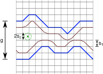
We study the diffusion through a two-dimensional channel with periodic boundary conditions in the horizontal x-direction. In the vertical y-direction the system is limited by two walls, see Fig. 1. These two walls are described by N points connected by straight lines, represented by the blue lines in Fig. 1. Thus, if one neglects the periodic boundary conditions the channel is of length N − 1. For numerical convenience the points of the channel wall reside on a lattice with unit lattice constant, which effectively determines the fundamental length scale of the system. Due to the horizontal periodic boundary conditions the two leftmost and the two rightmost wall points are identical. Their vertical distance (in the y-direction) is denoted by g, see Fig. 1. This gap opening parameter is one of the fundamental parameters of the system.We solely allow wall configurations in which the y-coordinates of nearest neighbour points within one wall differ by at most unity. This excludes the occurrence of extremely rugged walls. We consider channel walls with different contour lengths. The ruggedness parameter M1 describes the number of displacements of size ±1 which occur in a wall. Due to the periodic boundary constraint the number of jumps directed upwards must be equal to the one for jumps downwards for both walls. Consequently, M1 is an even number and lies in the interval [0,N − 1] (for odd N) or [0,N − 2] (for even N). We only consider configurations in which M1 is equal for the upper and lower walls. However, this does not confine our study to symmetric channels, compare Fig. 1.
Explicitly, to generate a given channel configuration we proceed along the following steps: we start with the upper wall at coordinate (0,g) and then move to the next lattice point 1,g + j, where j ∈ {−1,0,1}, and so on. The value of the vertical offset j is determined by a random number from the unit interval. A non-zero offset is chosen when the random number is smaller or equal to the ratio of the number of remaining vertical displacements (given by M1 minus the number of already performed nonzero vertical offsets) to the number of remaining intervals in the horizontal direction (N − 1 minus the number of already performed steps). From a second random number we decide whether a vertical offset is taken upwards or downwards. From these configurations we choose those for which the height of the final point at coordinate N is equal to g. This procedure guarantees that exactly the right number M1 of displacements will be implemented. After this, we further randomise the configuration by multiply interchanging the indices of the individual steps. An analogous procedure is followed to construct the lower channel wall. Finally, only those configurations are accepted for which the upper and lower walls do not touch or overlap.
Thus the width profile of the system is fully described by the gap opening parameter g and the two ‘displacement vectors’ of size (N − 1) for the upper and lower walls. The ith entry of this displacement vector denotes the difference between the y-coordinate of the (i + 1)st and ith wall points for each of the two walls (i is counted from left to right). Due to the constraints mentioned above only 0, ±1 are valid entries, and the sum of all entries per wall must be zero to fulfil the periodic boundary requirements.
The position of the random walking particle is described by the position of its centre of mass, illustrated by the green cross in Fig. 1. Its motion is off-lattice. This is shown in Fig. 1, where a circle of radius s2 (the step size of the random walk) is drawn around the particle's current position. For each step a random angle with respect to the x-axis is drawn, and the particle attempts to move its centre to the corresponding point on the dotted circle. To account for the diffusion of finite-size particles through the channel, before executing a step we check whether the distance from the current position to the wall is sufficient. To this end, the minimal distance to the wall is calculated for the trial position. Only if it is larger than the particle size s1, the step is actually performed. This accessible space is limited by the two dotted brown lines in Fig. 1. Their vertical distance is the effective channel width of the finite-size particle, and it is the quantity to be inserted into eqn (3) and (4). If the particle aims to move at a forbidden position, the step is cancelled and the particle remains at its current position, but time is increased by one unit. This corresponds to ‘sticky’ boundary conditions, which mimic transient binding to the channel wall.
The diffusing particle is initially placed in the middle of the channel in both x and y directions. However, if such a starting position is not possible in the sense described above, the given channel configuration is dismissed and a new one chosen. Tmax random walk steps are performed and the position in the x direction is traced and analysed. If not stated otherwise, for each parameter set g and M1 the results were averaged over 25![[thin space (1/6-em)]](https://www.rsc.org/images/entities/char_2009.gif) 000 configurations using the parameters N = 100, Tmax = 106, s1 = 1, and s2 = 0.6.
000 configurations using the parameters N = 100, Tmax = 106, s1 = 1, and s2 = 0.6.
III. Evaluation procedure
A quantity of central interest when tracking the motion of single particles is the time-averaged mean squared displacement (TA MSD) | (5) |
 | (6) |
 | (7) |
![[thin space (1/6-em)]](https://www.rsc.org/images/entities/char_2009.gif) 000. Here and in the following 〈·〉 denotes the ensemble average over channel realisations. Note that the ensemble of trajectories was obtained by generating a single random walk trajectory for each wall configuration, with the exception of the results presented in Section IV A, where the ensemble consisted of trajectories obtained with the same wall configuration.
000. Here and in the following 〈·〉 denotes the ensemble average over channel realisations. Note that the ensemble of trajectories was obtained by generating a single random walk trajectory for each wall configuration, with the exception of the results presented in Section IV A, where the ensemble consisted of trajectories obtained with the same wall configuration.
At first we address whether the observed motion corresponds to normal Brownian diffusion characterised by the mean squared displacement
 | (8) |
 we distinguish subdiffusion (0 < α < 1) and superdiffusion (α > 1).28,29 Subdiffusion of submicron tracers is quite widely observed in systems with a dense and highly structured environment, including the motion of tracer beads in reconstituted F-actin networks30 or in wormlike micellar solutions31 or the passive, thermally driven motion of labelled messenger RNA in living bacteria cells,32 of the infectious pathway of adeno-associated viruses in living HeLa cells,5 and of endogenous granules in living fission yeast and MIN6 insulinoma cells.33,34 Anomalous diffusion may be ergodic, that is, the time averaged MSD
  for sufficiently long trajectories converges to the ensemble quantity 〈x2(t)〉. However, there also exists stochastic dynamics for which so-called weak ergodicity breaking occurs, and
  and 〈x2(t)〉 behave differently.35–38
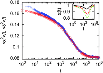
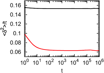
As transient anomalous diffusion behaviour is not readily discernable in a conventional log–log plot of the MSD versus time, we visualise the data in terms of the MSD divided by time, as a function of the logarithm of time, see ref. 39 and 40. This method emphasises deviations from normal diffusion behaviour: curves with a negative slope represent subdiffusion. A typical plot is shown in Fig. 2. We observe a weaker form of transient subdiffusion for times up to some 103 time steps. At longer times, there occurs a crossover to a more pronounced subdiffusive regime, which persists until approximately 105 time steps. After that, terminal normal diffusion appears. Such behaviour could also be interpreted as hindered diffusion or as a process characterised by a time-dependent diffusion coefficient.40,41 We note that both time and ensemble MSD coincide at longer times, which confirms the ergodic nature of the diffusion process. On shorter time scales the EA MSD curve lies above the EATA MSD curve due to the fact that, by construction, at the beginning of each trajectory the particle is placed in the middle of the channel. At such short times the probability that the particle sticks to the wall is greatly reduced compared to later times, and thus the EA MSD attains larger values than the EATA MSD, which averages the behaviour along the entire time series. The anomalous behaviour displayed in Fig. 2 is one of the major results of this study.
In the following we study the slowing-down of the particle diffusion in terms of two quantities. First, in the normal diffusive behaviour beyond 105 time steps we fit the EATA MSD data with a linear function in order to obtain the effective long time diffusion coefficient Deff. This quantity is then compared with the theoretical value Deff,DP given by eqn (4), since for each channel configuration we calculate DDP(x) via Dagdug and Pineda's formula (3), where w(x) is replaced by the effective channel width. We normalise the value of the effective long time diffusivity by the corresponding value in the absence of walls, Drel = Deff/D0. Second, we obtain the anomalous diffusion exponent α on time scales ranging from 103 to 105 time steps. Similar results are obtained by studying the mean maximal excursion of the particle42 (data not shown). This somewhat arbitrary choice of the time range in which α is fitted is motivated by the fact that most of the curves showed the more pronounced subdiffusive behaviour in this time regime. We use this averaged scaling exponent as a characteristic of our system and analyse its dependence on other parameters below. Alternatively, a time-local scaling exponent can be defined via . This quantity is plotted in the inset of Fig. 2 for the ensemble of configurations described by the main figure (red symbols) and two other ensembles with g = 6: M1 = 10 (black symbols) and M1 = 70 (green symbols). The inset clearly underlines our statement that normal diffusive behaviour is only observed in the short-time limit and in the long-time limit, whereas on intermediate time-scales, transient subdiffusive behaviour of variable values occurs. Thus, the fitted value of α studied in the remainder of this work can be considered as an effective value of the exponent for an intermediate time range.
IV. Results
A. Fixed channel wall configuration
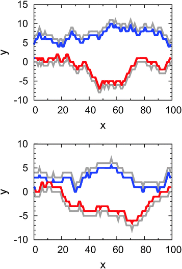
Before studying the effect of different parameter sets g and M1 to characterise the diffusion through this class of corrugated channels, we investigate in detail the features seen in Fig. 2 from simulations with fixed channel wall configurations.We explicitly consider three exemplary configurations to illustrate the effect of the sticky boundary conditions. These configurations are characterised by the parameter pairs g = 6 and M1 = 0, g = 4 and M1 = 30, and g = 6 and M1 = 50. The two configurations with non-flat walls are shown in Fig. 3. The grey curves denote the actual position of the channel walls, while the bold blue and red curves mark the region, which is inaccessible for the particle's centre.
While for a given wall configuration we make sure that the particle finds sufficient space in the middle of the channel where it is initially placed, it is a priori not certain that the particle can traverse the entire channel. This is the case when at some point the upper and lower walls are sufficiently close so that the finite-size particle cannot pass through such a bottleneck. Strictly speaking such a passage is impossible if there exists a horizontal interval whose width is at least of the step size s2. Otherwise, due to the finite step size the particle can actually ‘tunnel’ through such bottlenecks. The wall configuration depicted in the upper panel of Fig. 3 does not allow such a tunnelling for the given parameters g = 6 and M1 = 50: the red and the black curve do not overlap. The situation is different in the lower panel of Fig. 3 with g = 4 and M1 = 30: the channel is blocked for the particle at x ≈ 12.
However, even if inaccessible regions in a given wall configuration exist but the overlap of the walls stretches over less than the distance 2 × s2, such a narrow straight constitutes a severe entropic bottleneck for the diffusing particle: there exists an appreciable possibility that the particle repeatedly sticks to the channel walls. To quantify the influence of the sticky walls we binned the channels into 99 cells of length l and extracted from our simulations how often the particle unsuccessfully tries to move to a new position while being in the corresponding bin.
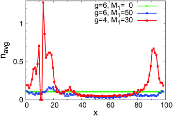
We first study the mean number navg of unsuccessful attempts for the three above sample configurations as a function of the particle position along the channel in Fig. 4. The green curve for the parameters g = 6 and M1 = 0 shows that for flat walls navg is approximately constant. The fact that this value is finite is a consequence of the sticky boundary condition at the edges of the system: namely, move attempts which would end at a position which is forbidden due to the finite size of the particle are not executed. If reflective walls or diffusion in free space were considered, any step could be executed and then navg = 0. In the present case, the value of navg depends on the step size and the (constant) width of the channel. From Fig. 4 we deduce that navg ≈ 0.1056.
The blue curve in Fig. 4 for g = 6 and M1 = 50 shows some variation as a function of x: where the channel is narrow, e.g., around x ≈ 20 in the upper panel of Fig. 3, navg is much higher than at locations where the channel is wider, e.g., in the middle of the channel. Comparing the minimum and maximum of navg along the channel, the variation of navg makes up a factor of approximately 7. This effect is much more pronounced in the red curve in Fig. 4 for the parameters g = 4 and M1 = 30, corresponding to the lower panel of Fig. 3: the curve is broken as two bins of the channel are inaccessible for the particle. In the bin to the right of the channel blockage the average number of unsuccessful tries is larger than 1. In other regions of the channel navg attains values similar to the ones in the other two configurations. Hence, the mean number of unsuccessful motion attempts along the channel directly reflects the effective channel width and thus the local transport properties.
Additional information can be deduced from studying the probability distribution p(nuns) of the number nuns of unsuccessful motion attempts in a row shown in Fig. 5, where we focus on the most distinct configuration with parameters g = 4 and M1 = 30 corresponding to the lower panel of Fig. 3. For better visibility we only consider extreme cases: namely, only the two bins with the highest and the two bins with the lowest mean number of motion attempts. In all four cases, the probability to find higher values of nuns decreases. In regions where the channel is wide (green and blue symbols in Fig. 5) this decay is very fast, such that within our simulation time there were never more than 19 subsequent unsuccessful attempts. Otherwise, it becomes obvious that near severe bottlenecks the distribution of waiting times is much more heavy-tailed (black and red symbols in Fig. 5). Up to 100 unsuccessful attempts in a row are possible, with a probability of about 10−6.
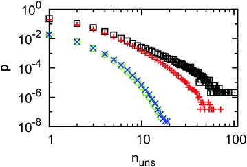 | ||
| Fig. 5 Probability distribution for the number of subsequent unsuccessful motion attempts, nuns, obtained with the wall configuration corresponding to the lower panel of Fig. 3 with parameters g = 4 and M1 = 30. We show the statistics for the bins centred around: x = 12.5 (black symbols), x = 13.5 (red symbols), x = 57.5 (green symbols), and x = 69.5 (blue symbols). The symbols for x = 57.5 are almost fully covered by those for x = 69.5. | ||
With this information, let us go back to the features of Fig. 2. According to the Fick–Jacobs theory, whenever the width of the channel changes in the form of a bottleneck or a bulge, this slows down the diffusion of the particle:9 in the case of a bottleneck the particle may be reflected back, while in the case of a bulge the particle may execute many motion events off the minimal path along the channel. The effect of the entropic bottlenecks in our present case is amplified by the presence of the sticky boundary conditions. On all time-scales on which the particle interacts with the walls, it is slowed down in comparison to a particle moving in free space. At this point, we have to differentiate between relatively flat and rugged channel walls. In the former case it is expected that an effective, constant diffusivity characterises the motion along the entire channel, since there is no typical bulge size. In particular, no transient subdiffusion should occur. In the latter case, however, the combined effect of entropic bottlenecks and sticky boundaries induces the transient subdiffusion in the ensemble and time averaged trajectories. This can also be understood when considering two very different representatives of channels characterised by the maximal value of M1 (see appendix).
On very long time scales, when the configurations shown in Fig. 3 are equivalent to a single step size in a coarse-grained random walk on the whole periodic structure, normal diffusive behaviour is restored, but now with a reduced diffusion coefficient. This reduced coefficient takes into account all the intermediate contacts with the channel walls. Thus, it is expected that more corrugated and/or tighter channels, which imply more frequent interaction with the walls, should show reduced values of α and a reduced effective diffusion coefficient on the ensemble level. To study these effects, in the following we systematically study the impact of the parameters g and M1 on the transport through the channels in ensembles of size 25![[thin space (1/6-em)]](https://www.rsc.org/images/entities/char_2009.gif) 000, where for each configuration we generate one random walk trajectory.
000, where for each configuration we generate one random walk trajectory.
B. Simulations of channel ensembles
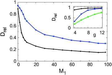
Two main simulation series were performed with the fixed values g = 6 and g = 4 for the gap opening parameter and 15 different values of the wall ruggedness parameter M1, spanning the whole possible range [0,98]. The fitted values of the normalised effective diffusion coefficient in the long-time regime, Drel, are depicted in Fig. 6 as a function of M1. Here and in the following, solely the EATA MSD values were used, as they supply the most extensive data. The results obtained with the EA MSD data are very similar (data not shown), which is not surprising due to the ergodicity of the process at long times. In both cases, an increase of the wall ruggedness (larger M1 values) effects slower effective diffusion. The slope of this decrease is steepest for small M1 values and then gradually flattens off. Conversely, at fixed values of M1 the effective diffusion is always substantially faster for g = 6 than g = 4.To study the impact of the gap opening parameter g in more detail, we took five different values at fixed values of the wall ruggedness parameter, namely, M1 = 0, M1 = 10, and M1 = 50. Thus, we consider flat channels, slightly corrugated, and heavily corrugated channels. The corresponding results for the fitted values of the normalised effective diffusion constant Drel are shown in the inset of Fig. 6. For fixed values of g we see once more that the diffusion is quickest when the wall is smoother, i.e., when M1 is smaller. As was already observed in the preceding paragraph a wider gap opening at a fixed value of M1 leads to faster diffusion. Thus, wider channels can be traversed quicker.
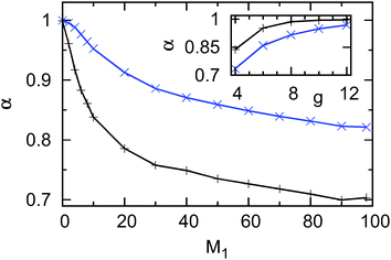
At first sight surprisingly, we observe that even for completely flat upper and lower channel walls (M1 = 0, black line in the inset of Fig. 6) the diffusion in tighter channels is slowed down in comparison to the situation in free space. This is not expected in systems with reflecting boundaries, which are usually described with the Fick–Jacobs equation. However, for the finite-size particles studied here it is the result of the sticky boundary conditions at the channel walls: in a tighter channel the particle is more often close to the walls and binds transiently. Alternatively, the slow-down due to the interaction with the walls can be quantified by measuring the anomalous diffusion exponent α in the intermediate time regime, on time scales of 103 to 105 simulation steps. The fitted values for α are depicted in Fig. 7 as a function of the ruggedness M1. The same trend as for the effective diffusion coefficient is seen for the anomalous diffusion exponent α of the transient subdiffusive regime. For increasing contour lengths of the channel wall the motion is increasingly subdiffusive. As expected, the transient subdiffusion is heavier for the tighter channel (g = 4).
The dependence of α on the gap opening parameter is shown in the inset of Fig. 7. In this case, only values obtained with corrugated channels (M1 = 10 and M1 = 50) are shown. Note that in flat channels with M1 = 0 no transient subdiffusion occurs, see above. Again, the curves for α are similar to the ones obtained for the effective diffusion coefficient: α is an increasing function of g and M1 = 10 leads to less pronounced transient subdiffusion than M1 = 50. This analogy motivates the study of the relation between α and Drel in more detail.
In Fig. 8 we plot all α values for gap openings g = 4 and g = 6 as a function of the corresponding fitted values of Drel. The results show that there is a strong (nonlinear) correlation between both parameters. For increasing values of Drel the value of α also increases, with decreasing slope. The relation between both parameters is bijective, thus, both quantities are appropriate and sufficient to quantify the slow-down of the motion along the channel. For similar values of Drel the values for α obtained with the tighter channels (g = 4) are slightly larger than those for the wider channels (g = 6). However, this fact should not be overstated: all data sets were fitted in the time interval 103 to 105, irrespective of the exact shapes of the curves. It is conceivable that a closer connection between the values for α could have been obtained by choosing the fitting time window for each curve individually. We note that this relation between the scaling exponent α and the effective diffusion coefficient was recently studied in molecular dynamics simulations dealing with proton and water mobility in (tetramethyl)urea solutions.43
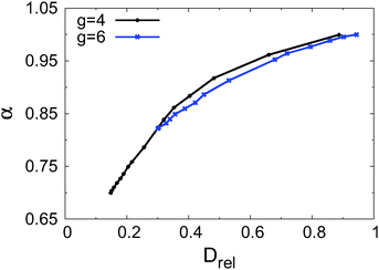 | ||
| Fig. 8 Anomalous diffusion exponent α of the transiently subdiffusive regime as a function of the long-time diffusion exponent Drel with gap opening parameters g = 4 (black) and g = 6 (blue). | ||
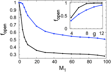
As mentioned above, in an ensemble of systems with corrugated boundaries not all channels can be traversed completely. If a channel is blocked somewhere, the corresponding squared displacement of the particle position has an upper limit. On an ensemble level these trajectories will reduce the average values of α and Drel, since this is one of the main factors contributing to the anomalous features of Fig. 2. Thus, it is important to extract from our simulations solely the unblocked configurations. The corresponding parameter fopen is plotted as a function of the ruggedness M1 for fixed gap openings g = 4 (black symbols) and g = 6 (blue symbols) in Fig. 9, and as a function of the gap opening g (for M1 = 10 and M1 = 50) in the inset of Fig. 9. An inspection of Fig. 9 shows that this fraction is a decreasing function of M1 and an increasing function of g. Overall, the curves look similar to the ones of the normalised effective diffusion coefficient Drel (compare Fig. 6).
To better understand why above a certain threshold of the boundary ruggedness parameter M1 the effective diffusion coefficient only decreases slightly (see Fig. 6), it is instructive to study the average weighted effective width wwgt of the channels. Here, weighted means that for any blocked channel the width is set to zero. The weighted width is plotted as a function of M1 in Fig. 10. For increasing, yet small values of M1 the effective weighted channel width decreases, until it reaches a shallow minimum. For larger values of M1 it rises to higher values than at the origin, slowly approaching a plateau.
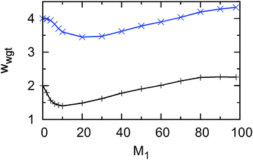 | ||
| Fig. 10 Weighted effective channel width wwgt as a function of channel ruggedness M1 for gap opening g = 6 (blue line and symbols) and g = 4 (black line and symbols). | ||
Due to the procedure to generate the wall configurations, for those geometries with a low value of both g and M1, there is a substantial probability that the passage is blocked: after a displacement in one wall which decreases the effective channel width to a critical value, there are not many possibilities which could increase it again. At the same time the maximum width is rather restricted due to the low total number of displacements. The situation becomes different above a certain threshold: heavily rugged walls which reach a critical value have many more opportunities to become wider again and they can reach far bigger widths. Thus, the average width of those traversable channels is larger for more rugged wall configurations. This facilitates the transport through these configurations, as the sticky boundaries are further away. However, as remarked earlier, more rugged walls slow down the diffusion due to the occurrence of bulges and constrictions,9 such that we have two opposing effects, which mostly (almost) cancel each other. Consequently, Drel remains nearly constant above a threshold value of M1 (compare Fig. 6).
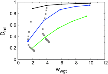
Fig. 11 shows the normalised effective diffusion coefficient Drel as a function of the weighted channel width wwgt. For better visibility data points with identical M1 values are connected by lines (M1 = 0: black line, M1 = 10: blue line, and M1 = 50: green line). While for a fixed value of M1 more spacious channels allow faster diffusion, the heavy scatter between values of Drel obtained with similar values of wwgt (grey symbols) shows that the knowledge of the mean channel width of an ensemble of channels alone is insufficient to predict the transport properties. At the same time an inspection of Fig. 6 shows that a single of the parameters g and M1 is not sufficient to make such a prediction. At least two such parameters are needed.
C. Displacement autocorrelation function
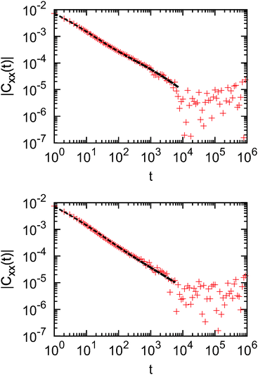
Another possibility to assess the transport properties of our channel systems is to calculate the velocity autocorrelation function. This quantity is particularly interesting since it is long known that in the case of two-dimensional (hard-disk) fluids the diffusion coefficient calculated via the Green–Kubo formula diverges due to the power-law scaling of the autocorrelation function.44–47Since, by definition, there is no velocity in our random walk simulation we calculate the displacement autocorrelation function along the channel Cxx,i(t) for the ith time series, which is defined as:
 | (9) |
 . The data show that this function stays negative for small and intermediate time regimes and slowly levels off to zero. On longer timescales the function fluctuates around zero. Thus, in order to conveniently create a log–log plot in Fig. 12 we show the absolute value of this function for two ensembles characterised by the parameters g = 4, M1 = 30 (upper panel) and g = 6, M1 = 50 (lower panel).
For t ≲ 104 time steps both data sets are almost of power-law form, however, on a closer look two shoulders may be discerned around such a power-law trend. The curves can be approximated very well by a fit function, which is the sum of two stretched exponential functions: Cfit(t) = c1![[thin space (1/6-em)]](https://www.rsc.org/images/entities/char_2009.gif) exp(atb) + c2
exp(atb) + c2![[thin space (1/6-em)]](https://www.rsc.org/images/entities/char_2009.gif) exp(ctd). The data are thus consistent with a fast, exponential decay. Note that at times shorter than 105 time steps the particle still has not explored the entire channel. At longer times the correlations will clearly be negligible so that the Green–Kubo integral converges.
exp(ctd). The data are thus consistent with a fast, exponential decay. Note that at times shorter than 105 time steps the particle still has not explored the entire channel. At longer times the correlations will clearly be negligible so that the Green–Kubo integral converges.
V. Comparison with Dagdug and Pineda's formula
In order to compare our results obtained from ensembles of channel configurations with the results of Dagdug and Pineda, we make a simplifying assumption: for all unblocked configurations, we determine DDP(x) from eqn (3) and subsequently Deff,DP from eqn (4). For all blocked configurations the effective diffusivity Deff,DP = 0 accounts for the fact that on long time-scales particles in these configurations do not contribute significantly to the MSD. Finally, we average over all configurations in the ensemble and normalise through division by the diffusion coefficient in free space, Drel,DP = 〈Deff,DP〉/D0. We compare these values with our fitted values of the normalised diffusion coefficient in the upper panel of Fig. 13, where data points with the same value of the gap opening g are represented in the same colour.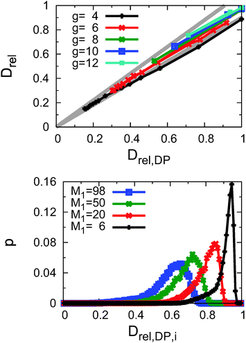 | ||
| Fig. 13 Upper panel: normalised effective diffusion coefficient Drel from our simulations in the sticky, corrugated channel as a function of the value Drel,DP obtained from the results (3) of Dagdug and Pineda. Black: gap opening parameter g = 4, red: g = 6, green: g = 8, blue: g = 10, and cyan: g = 12. The two grey lines mark the range of ±10% around the theoretical value. Lower panel: distributions of effective diffusion coefficients for individual unblocked channel configurations obtained with Dagdug and Pineda's formula. Parameters: g = 6 in all four cases. M1 = 6: black, M1 = 20: red, M1 = 50: green, M1 = 98: blue. | ||
This is another major result of our study: as demonstrated in the upper panel of Fig. 13, for fixed values of the gap opening g there is a linear relation between Drel and Drel,DP. Most of the data points are located within a 10% confidence interval around Dagdug and Pineda's values. More explicitly, a linear fit of the data points obtained in a simulation series yields the following results. For g = 4, the fitted relation between the two is Drel = (0.018 ± 0.004) + (0.853 ± 0.009)Drel,DP, while for g = 6 we find Drel = (0.032 ± 0.095) + (0.903 ± 0.007)Drel,DP. For g = 8, 10, and 12 we did not fit the data as there were only three values available.
The fact that the slope of the fits is somewhat below 1 shows that Dagdug and Pineda's formula, which only applies to systems with perfectly reflecting boundaries, slightly overestimates the diffusion coefficient compared to our system with sticky boundary conditions. Thus, as expected the additional interaction with the boundaries further slows down the diffusion, which is already reduced by the occurrence of entropic bottlenecks. This reasoning is further substantiated by the observation that in tighter channels (with g = 4), where these surface effects play a more important role, the slope of the conversion formula is smaller, and the deviation from Dagdug and Pineda's formula is more pronounced. Given the quite intricate form of the effective channel width (see Fig. 1 and 3) it is not feasible to quantify this effect analytically. However, in the future other values of s1 and s2 could be considered to study the magnitude of the correction terms numerically.
Deviations of our results from Dagdug and Pineda's formula are also based on the fact that their analysis applies to one given channel configuration. Driven by the physical application we here consider an ensemble of different channel wall configurations, solely defined by the fixed macroscopic parameters g and M1. Individual configurations may therefore differ considerably, even if they share the values of g and M1. This is illustrated in the lower panel of Fig. 13, where for all unblocked configurations the expected effective diffusion coefficient was calculated with Dagdug and Pineda's formula. For g = 6 and four different values of M1 we see that the distribution of values of Drel,DP is far from narrow. The values increasingly scatter for more rugged conformations (higher values of M1). Thus, the semi-quantitative agreement of our data with the theoretical prediction on an ensemble level is indeed remarkable.
VI. Conclusion and outlook
We studied the motion of finite-size particles through randomly corrugated channels with sticky walls, observing transient anomalous diffusion of the particles in their passage of the channel. We also obtained the long-time diffusion coefficient for this motion on time scales over which normal Brownian diffusion is restored. The control parameters in our study were the gap opening parameter fixing the distance between the channel walls at the entrance and the exit of the channel, as well as the wall ruggedness parameter setting the maximal variation of the channel wall configuration. We quantified the dependence of the anomalous diffusion exponent and the long-time diffusion coefficient as a function of the ruggedness and gap opening, and showed that both quantities are in fact correlated. We especially analysed the blocked channels, which the particle cannot fully traverse. The long-time effective diffusion coefficient was shown to agree well with the prediction for point-like particles in channels with reflecting boundary conditions by Dagdug and Pineda.It will be interesting to study different models for the construction of the random channel walls, for instance, by adding correlations in the growth algorithm. Moreover it will be of relevance to replace the single particle scenario and consider an ensemble of diffusing particles with excluded volume.
Appendix: V-shaped and saw-tooth channels
In order to illustrate that two channels with the same values of g and M1 can have very different transport properties, we consider here two configurations with the maximal value of M1 = 98. One is a V-shaped channel for which both upper and lower boundaries move upwards in the left half of the channel and back downwards in the right half of the channel. Technically this means that for both walls every vertical offset is plus one in the left half and minus one in the right half. The other channel has walls with a saw-tooth shape. Again the values of the offsets are equal for the upper and lower wall, however, this time the offsets alternate between +1 and −1. In Fig. 14, which is analogous to Fig. 2, we plot the EATA MSD divided by time of 10![[thin space (1/6-em)]](https://www.rsc.org/images/entities/char_2009.gif) 000 trajectories in these two channels.
000 trajectories in these two channels.
For the V-shaped channel (red curve), already on short time scales the particle often encounters the channel walls such that the time-local diffusion coefficient plotted here attains values considerably smaller than that in free space (0.18). The corresponding values decrease further until around 50 time steps after which the value of the diffusion coefficient remains nearly constant.
Even though the words saw-tooth seem to imply a rather rugged wall shape, the bulges in the effective width are rather small, such that the particle experiences a nearly flat channel, beyond the time scale for crossing a single tooth. Accordingly, the diffusion coefficient at the shortest timescales is very close to the value in free space and after a small decrease it is nearly constant on all timescales. As for really flat channels, only the effective long-time diffusion coefficient is reduced, but no transient subdiffusion is observed.
Thus, these two channels constitute extreme cases of the distribution shown in the lower panel of Fig. 13, where it can be seen that for M1 = 98 the distribution of effective diffusivities is very broad.
Acknowledgements
MB and AG acknowledge funding from the German Federal Ministry for Education and Research, and RM from the Academy of Finland within the FiDiPro scheme.References
- L. W. Gelhar, C. Welty and K. R. Rehfeldt, Water Resour. Res., 1992, 28, 1955 CrossRef CAS; B. Berkowitz, A. Cortis, M. Dentz and H. Scher, Rev. Geophys., 2006, 44, RG2003 CrossRef.
- R. Kimmich, NMR: Tomography, Diffusometry, Relaxometry, Springer, Berlin, 2011 Search PubMed.
- J. Kärger and D. M. Ruthven, Diffusion in Zeolites and Other Microporous Solids, Wiley, New York, 1992 Search PubMed.
- T. Kühn, T. O. Ihalainen, J. Hyväluoma, N. Dross, S. F. Willman, J. Langowski, M. Vihinen-Ranta and J. Timonen, PLoS One, 2011, 6, e22962 Search PubMed.
- G. Seisenberger, M. U. Ried, T. Endreß, H. Büning, M. Hallek and C. Bräuchle, Science, 2001, 294, 1929 CrossRef CAS PubMed.
- A. G. Cherstvy, A. V. Chechkin and R. Metzler, Soft Matter, 2014, 10, 1591 RSC.
- L. Liu, P. Li and S. A. Asher, Nature, 1999, 397, 141 CrossRef CAS PubMed.
- P. S. Burada, P. Hänggi, F. Marchesoni, G. Schmid and P. Talkner, ChemPhysChem, 2009, 10, 45 CrossRef CAS PubMed.
- R. Zwanzig, J. Phys. Chem., 1992, 96, 3926 CrossRef CAS.
- D. Reguera and J. M. Rub, Phys. Rev. E: Stat., Nonlinear, Soft Matter Phys., 2001, 64, 061106 CrossRef CAS.
- P. Kalinay and J. K. Percus, J. Chem. Phys., 2005, 122, 204701 CrossRef CAS PubMed.
- P. Kalinay and J. K. Percus, Phys. Rev. E: Stat., Nonlinear, Soft Matter Phys., 2005, 72, 061203 CrossRef CAS.
- P. Kalinay and J. K. Percus, Phys. Rev. E: Stat., Nonlinear, Soft Matter Phys., 2006, 74, 041203 CrossRef CAS.
- A. M. Berezhkovskii, M. A. Pustovoit and S. M. Bezrukov, J. Chem. Phys., 2007, 126, 134706 CrossRef CAS PubMed.
- P. Kalinay and J. K. Percus, Phys. Rev. E: Stat., Nonlinear, Soft Matter Phys., 2008, 78, 021103 CrossRef.
- S. Martens, G. Schmid, L. Schimansky-Geier and P. Hänggi, Phys. Rev. E: Stat., Nonlinear, Soft Matter Phys., 2011, 83, 051135 CrossRef CAS.
- A. Berezhkovskii and A. Szabo, J. Chem. Phys., 2011, 135, 074108 CrossRef PubMed.
- P. Kalinay, Phys. Rev. E: Stat., Nonlinear, Soft Matter Phys., 2013, 87, 032143 CrossRef.
- S. Martens, A. V. Straube, G. Schmid, L. Schimansky-Geier and P. Hänggi, Phys. Rev. Lett., 2013, 110, 010601 CrossRef CAS.
- R. M. Bradley, Phys. Rev. E: Stat., Nonlinear, Soft Matter Phys., 2009, 80, 061142 CrossRef.
- L. Dagdug and I. Pineda, J. Chem. Phys., 2012, 137, 024107 CrossRef PubMed.
- S. Lifson and J. L. Jackson, J. Chem. Phys., 1962, 36, 2410 CrossRef CAS PubMed.
- R. Festa and E. D'Agliano, Physica A, 1978, 90, 229 CrossRef.
- J. J. Kasianowicz, E. Brandin, D. Branton and D. W. Deamer, Proc. Natl. Acad. Sci. U. S. A., 1996, 93, 13770 CrossRef CAS; L. Brun, M. Pastorizo-Gallego, G. Oukhaled, J. Math, L. Bacri, L. Auvray and J. Pelta, Phys. Rev. Lett., 2008, 100, 158302 CrossRef.
- L. Dagdug, A. M. Berezhkovskii, Y. A. Makhnovskii and V. Y. Zitserman, J. Chem. Phys., 2008, 129, 184706 CrossRef PubMed.
- W. Riefler, G. Schmid, P. S. Burada and P. Hänggi, J. Phys.: Condens. Matter, 2010, 22, 454109 CrossRef CAS PubMed.
- M. L. Henle, B. DiDonna, C. D. Santangelo and A. Gopinathan, Phys. Rev. E: Stat., Nonlinear, Soft Matter Phys., 2008, 78, 031118 CrossRef.
- R. Metzler and J. Klafter, Phys. Rep., 2000, 339, 1 CrossRef CAS.
- R. Metzler and J. Klafter, J. Phys. A: Math. Gen., 2004, 37, R161 CrossRef.
- I. Y. Wong, M. L. Gardel, D. R. Reichman, E. R. Weeks, M. T. Valentine, A. R. Bausch and D. A. Weitz, Phys. Rev. Lett., 2004, 92, 178101 CrossRef CAS.
- J.-H. Jeon, N. Leijnse, L. Oddershede and R. Metzler, New J. Phys., 2013, 15, 045011 CrossRef.
- I. Golding and E. C. Cox, Phys. Rev. Lett., 2006, 96, 098102 CrossRef PubMed.
- J.-H. Jeon, V. Tejedor, S. Burov, E. Barkai, C. Selhuber-Unkel, K. Berg-Sørensen, L. Oddershede and R. Metzler, Phys. Rev. Lett., 2011, 106, 048103 CrossRef.
- S. M. A. Tabei, S. Burov, H. Y. Kim, A. Kuznetsov, T. Huynh, J. Jureller, L. H. Philipson, A. R. Dinner and N. F. Scherer, Proc. Natl. Acad. Sci. U. S. A., 2013, 110, 4911 CrossRef PubMed.
- E. Barkai, Y. Garini and R. Metzler, Phys. Today, 2012, 65(8), 29 CrossRef CAS PubMed.
- S. Burov, J.-H. Jeon, R. Metzler and E. Barkai, Phys. Chem. Chem. Phys., 2011, 13, 1800 RSC.
- A. G. Cherstvy, A. V. Chechkin and R. Metzler, New J. Phys., 2013, 15, 083039 CrossRef.
- A. G. Cherstvy and R. Metzler, Phys. Chem. Chem. Phys., 2013, 15, 20220 RSC.
- P. A. Netz and T. Dorfmüller, J. Chem. Phys., 1995, 103, 9074 CrossRef CAS PubMed.
- M. Saxton, Biophys. J., 1996, 70, 1250 CrossRef CAS.
- A. M. Berezhkovskii, L. Dagdug and S. M. Bezrukov, Biophys. J., 2014, L09 CrossRef CAS PubMed.
- V. Tejedor, O. Bénichou, R. Voituriez, R. Jungmann, F. Simmel, C. Selhuber-Unkel, L. B. Oddershede and R. Metzler, Biophys. J., 2010, 98, 1364 CrossRef CAS PubMed.
- J. Xu, T. Yamashita, N. Agmon and G. A. Voth, J. Phys. Chem. B, 2013, 117, 15426 CrossRef CAS PubMed.
- B. J. Alder and T. E. Wainwright, Phys. Rev. A: At., Mol., Opt. Phys., 1970, 1, 18 CrossRef.
- M. H. Ernst, E. H. Hauge and J. M. J. van Leeuwen, Phys. Rev. Lett., 1970, 25, 1254 CrossRef.
- J. R. Dorfman and E. G. D. Cohen, Phys. Rev. Lett., 1970, 25, 1257 CrossRef.
- B. Lin, S. A. Rice and D. A. Weitz, Phys. Rev. E: Stat. Phys., Plasmas, Fluids, Relat. Interdiscip. Top., 1995, 51, 423 CrossRef CAS.
| This journal is © the Owner Societies 2014 |

