 Open Access Article
Creative Commons Attribution 3.0 Unported Licence
Systematic experimental charge density analysis of anion receptor complexes†
Isabelle L.
Kirby
a,
Mark
Brightwell
a,
Mateusz B.
Pitak
a,
Claire
Wilson
b,
Simon J.
Coles
*a and
Philip A.
Gale
*ac
aChemistry, University of Southampton, Southampton, SO17 1BJ, UK. E-mail: s.j.coles@soton.ac.uk; philip.gale@soton.ac.uk
bDiamond Light Source, Diamond House, Harwell Science and Innovation Campus, Didcot, Oxfordshire OX11 0DF, UK
cDepartment of Chemistry, Faculty of Science, King Abdulaziz University, Jeddah, Saudi Arabia
First published on 28th April 2014
Abstract
The first systematic electronic resolution study of a series of urea-based anion receptor complexes is presented. The hydrogen bonding in these multi-component systems was fully characterised using Bader's Quantum Theory of Atoms In Molecules (QTAIM) with the strength of the various N–H⋯anion hydrogen bonds quantified and the individual contributions of different intermolecular forces to the overall receptor: anion interaction derived by comparison of the charge densities in the related complexes. The strength of the N–H⋯anion hydrogen bonds was correlated to the basicity of the anion and related to the structure of the receptors. The geometric criteria used to identify hydrogen bonding interactions in standard resolution X-ray diffraction studies were shown to be valid for stronger interactions. However, these geometric criteria are less reliable and lead to assumptions that are not necessarily upheld when applied to weaker intermolecular interactions. The presence of these could only be confirmed by charge density studies. The effect that changes to the receptor substitution pattern have on the entire supramolecular system is illustrated by the differences in the electrostatic potential distributions and atomic charges across the series. The application of systematic high resolution studies to rationalise a variety of host–guest systems has been demonstrated.
Introduction
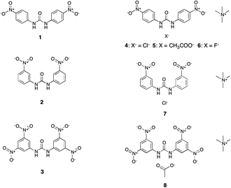
Supramolecular chemists design and synthesise molecules to associate with specific guests of interest via non-covalent intermolecular interactions.1 For example, the position and nature of hydrogen bond donor groups in neutral anion receptor compounds determine the selectivity of the receptor for anions.2 Appending electron-withdrawing or electron-donating groups to the parent hydrogen bond donor scaffold can modulate the acidity of the hydrogen bond donor groups and therefore the strength of the hydrogen bond interactions formed and so modulate affinity.3 Crystallography is often used to determine the structures of the receptors and complexes formed. Charge density investigations have been widely used to describe and classify intermolecular interactions in molecular crystals,4–7 with numerous studies on systems containing hydrogen bonding,8,9 halogen bonding,10–13 and weaker non-covalent interactions such as π⋯π and CH⋯π interactions.14–17 The advent of more powerful X-ray sources18 and diffractometry, coupled with the ability to readily refine high resolution X-ray diffraction data across series of complexes in a reasonable time-scale allows the study of the variation in charge density across a series of receptors with different substituents and the same guest or a single receptor with a variety of different guests. This allows detailed information on the nature of the host–guest interaction (for example the strength of the hydrogen bonding interactions and hence the stability of the complex) to be determined from the solid-state analysis of the complex. How these interactions change as functional groups on the periphery of the receptor are altered and as the receptor binds a variety of different guests can also be observed.In this paper a systematic study of a family of five urea-based anion receptor complexes (4–8 in Fig. 1) is described. The receptors were designed and modifications systematically introduced in order to gain a deeper understanding of the effects of anion basicity and receptor configuration on guest binding. By altering the bound anion across a series whilst maintaining a common receptor molecule, the influence of the anion on the nature of the interaction between the two components can be probed. Additionally, by including receptors where the functional groups are located in different substitution positions, it is also possible to assess the effect of this variation on the nature of the interaction with the anion.
The 1,3-bis(4-nitrophenyl)urea (1) receptor is maintained throughout a series of complexes with chloride (4), acetate (5) and fluoride (6) anions, which provides an insight into how variation in the basicity of the anionic guest affects the charge density distribution. Two pairwise comparisons, using systems binding the same anion (chloride and acetate respectively) probe the substituent position effect by contrasting (i) para (4) with meta (7) nitro substitution on the receptor and (ii) the electron-withdrawing nitro substituent in the para position (5) to that with 3,5-dinitro functionality (8).
Analysis of solid-state structures provides a wealth of highly accurate quantitative information that can be used to assess these effects and is a common tool in systematic studies. These structures have been previously discussed19 in this respect, however we have expanded this analysis by examining the electronic distributions derived from experimental high resolution X-ray diffraction data. This has been performed for all members of this comparison study and enables QTAIM (Quantum Theory of Atoms In Molecules)20 analysis of the electronic distribution. QTAIM defines chemical bonding and the structure of a chemical system based on the topology of the electron density distribution. Using criteria well established in charge density analysis the existence, classification and quantification of hydrogen bonding interactions was performed and was correlated to anion basicity and linked to trends in binding affinity observed in solution by proton NMR titration studies. The modelling of the electron density across the entire structure allows changes in the distribution to be related back directly to designed modifications of the receptor scaffold. The variations in the hydrogen bonding properties, the charges of individual units that constitute the structures and the electrostatic potential distributions of the structures have been fully compared.
This is the first study of anion receptor complexes by experimental charge density analysis, where the systematic nature of the study allows comparison of the electron density distribution as chemical alterations to the system are made. These multi-component structures, with each component bearing a different formal charge and consisting of a large number of atoms, represent some of the more complex systems currently reported using charge density analysis.
Coppens and Koritsanszky21 and also Macchi22 have highlighted further the technical aspects of charge density modelling and its applications across a broad range of chemical areas. The use of charge density analysis to study metal–metal interactions,23 organometallic systems,24,25 agostic interactions26 in metallic systems, polymorphism,27–32 and biologically relevant structures including amino acids33–40 illustrates this.
Of particular significance to this study is recent work by Nguyen et al., one of the first focusing on a host–guest supramolecular system, where the charge density distribution in a synthetic terephthaloyl receptor complexed to adipic acid has been resolved.41
Urea, the building block of our complexes has been a model compound through the development of charge density analysis42–44 and electron density distribution studies of urea derivatives45 and urea-based co-crystal systems28,46,47 have also been reported.
The benefits of a systematic approach, comparing the charge density distributions in related structures has been highlighted in previous work by Wozniak, studying proton sponges based on 1,8-bis(dimethylaminonaphthalene) (DMAN)48–50 and Pinkerton, examining a group of natural and synthetic estrogens.51,52 Both authors used systematic charge density studies to link the electronic distribution to the chemical properties of molecules.
The focus given herein to the effect of peripheral electron-withdrawing groups builds on earlier work by Grabowsky et al., who reported the effect of electron-withdrawing substituents on the electron density in the epoxide ring of a series of epoxide derivatives and hence their relative reactivities53 and Lecomte and co-workers in their studies on various nitro substituted imidazole compounds.54–56 Mata et al., have also studied the effect of substitution on the interaction energy of hydrogen bonds in FH⋯RF (R = H, Al, Li, Cl and CCH3) systems computationally.57
Experimental
For systematic studies of this nature involving complex structures with multiple components, the ability to collect high resolution, highly redundant data for all members of the structural library under investigation, is vital. This requires access to high-flux sources that enable collection of sufficient quality diffraction data for each structure over a reasonable time-scale, despite the presence in the family of one or two challenging structures or crystals of less ideal quality. High resolution X-ray diffraction datasets were collected either on high-flux home source diffractometers58 or the I19 beam line at Diamond Light Source.59The approach, protocols and procedures for the collection of very high resolution, high redundancy and quality diffraction data for charge density studies at the I19 beam line have not been previously defined. The data presented herein for the multipole refinements of structures 6, 7 and 8 are part of a study performed by the authors to explore the conditions for charge density quality data collection on the beam line and are the first such results to be published. Similar approaches were used to collect the diffraction data for both 4 and 5, which were collected using laboratory-based sources.
Modelling the electron density distribution in each crystal structure using the experimental X-ray diffraction data was performed using the multipole refinement model advocated by Hansen and Coppens.60 The electron density is described using the formula shown in eqn (1), where ρc(r) and ρv(r) are the spherical core and valence electron densities, the summation in the third term accounts for the valence electron deformations and the dlm± are density-normalised real spherical harmonics expressed in polar coordinates. The isolated atom valence density and the Slater type radial functions R1 are modified by the scaling factors (κ and κ′) to account for the radial expansion or contraction of the valence shell.
 | (1) |
Therefore for 5 and 7 the atomic positions and anisotropic displacement parameters (ADPs) for the hydrogen atoms determined from the neutron studies were incorporated into the multipole refinement model unchanged and kept fixed at these values throughout.
In the cases where hydrogen atom positional and displacement parameters were not available from neutron diffraction studies, 4, 6 and 8, a commonly used approach was employed; the positional and isotropic displacement parameters for hydrogen atoms were refined using reflections with sin(θ)/λ < 0.7 Å−1, the hydrogen atom positions were then extended along the bond vector to standard lengths as determined from neutron diffraction data for the appropriate functional group.63 The agreement with the bond lengths as determined in the neutron studies of 5 and 7 suggest that this is a valid approach for these complexes. For complexes 4, 6 and 8 the anisotropic displacement parameters (ADPs) were estimated using the SHADE (Simple Hydrogen Anisotropic Displacement Estimator) server.64 These were then imported into the multipole model and kept fixed.
In 6 the hydrogen atoms of the TMA were kept isotropic due to the large displacement parameters of the carbon atoms to which they are attached (caused by the disorder of this part of the crystal structure) and because the positional and anisotropic displacement parameters of the atoms in the TMA cation (which was modelled using InvariomTool65) were kept fixed throughout the multipole refinement. The derived ADPs from the SHADE server were physically unreasonable and suggested that this group was not fully rigid due to the disorder of this unit.
The multipole refinements were performed using the XD200666 software suite with the core and valence scattering factors of all atoms derived from the Clementi–Roetti wave functions.67 The refinement was performed on F for all reflections with I > 3σ(I).
Initially, only the scale factor was refined against the whole resolution range of diffraction data. The positional and anisotropic displacement parameters of the non-hydrogen atoms were refined against the reflections with sin(θ)/λ > 0.7 Å−1. The hydrogen atom parameters for each complex were then treated as described above. Next, multipole populations were refined with the level of multipole gradually increased from monopole up to the final level: hexadecapole for heteroatoms while those of the carbon atoms were truncated at the octopole level. For the hydrogen atoms a single bond directed dipole population was refined. For non hydrogen atoms an expansion (κ) parameter was refined while κ′ was fixed as 1.00. Chemically equivalent atoms were constrained to share the same expansion/contraction (κ/κ′) parameters while throughout the multipole refinement the κ/κ′ parameters were fixed to values of κ = κ′ = 1.20. A consistent local coordinate axis system was used for all the structures. An overall charge neutrality constraint was applied to all of the structures in this study. In the final stages of refinement all variables with the exception of the κ parameters, to allow for convergence, were refined together. The X-ray data used in the refinement were truncated to an appropriate sin(θ)/λ limit as outlined by Herbst-Irmer et al.68 For all the crystal structures the Hirshfeld rigid bond test69 was applied in the final stages of the refinement and the values of the difference of mean square displacement amplitudes (DMSDAs) were <10−4 for the all the non-hydrogen atom bonds except some of those of the TMA groups in 6 and 8.
Initially, unconstrained refinement of the nitro groups produced a chemically unreasonable range of ∇2ρ(rBCP) values. Woźniak and co-authors have previously observed similar behaviour in nitro groups.70,71 Consequently mm2 symmetry constraints for the nitrogen atoms of these groups were imposed and the two oxygen atoms in each nitro group were constrained to be chemically identical.
The TMA cation in 6 was initially modelled as ordered with the central N-atom lying on a 2-fold rotation axis and just two independent methyl groups. However this model results in large, elongated ADPs and an unsatisfactory modelling of the electron density distribution of this cation with unacceptably large peaks in the residual electron density. Attempts were made to obtain a very low temperature (35 K) high-resolution X-ray diffraction dataset to address this problem. However this approach was hampered by a phase transition in 6, which occurred below 60 K and the resulting unit cell has a much larger asymmetric unit and split peaks making it unsuitable for a charge density study.19 A 65 K high resolution X-ray diffraction dataset was collected, and mirrored the behaviour observed in the 100 K structure so the higher temperature, 100 K, dataset was retained for consistency. In order to improve upon the initial model a disorder model for the TMA cation was introduced in which the central nitrogen atom no longer lies on the 2-fold axis but is slightly displaced from it and forms the centre of a half-occupied TMA cation with 4 independent methyl groups. A second orientation of the TMA cation is generated by the application of the 2-fold rotation. This model was then imported into the XD program, the positions and ADPs for the non hydrogen atoms in the TMA group were kept fixed and those of the hydrogen atoms extended along the bond vector to neutron diffraction derived distances and then fixed. The Invariom database72,73 was then used to determine the multipole populations and κ and κ′ values for each atom of TMA and transferred to the XD input using InvariomTool.65 These database multipole parameters for TMA were then kept fixed during the refinement of the electron density in the remaining parts of the structure, in a similar manner to that employed by Kratzert et al.74 This final model using a combination of the disorder model and the Invariom database values was considered to be more suitable due to the significant drop in R(F) factor, GoF (Table 1) and the substantial reduction in the residual density around the TMA cation. The residual density analysis and fractal dimension distribution plots75 also graphically illustrate this improvement in the model (see ESI†).
| Structure | 4 | 5 | 6 | 7 | 8 |
|---|---|---|---|---|---|
| Formula | C17H22ClN5O5 | C19H25N5O7 | C30H32FN9O10 | C17H22ClN5O5 | C19H23N7O11 |
| Crystal system | Triclinic | Triclinic | Orthorhombic | Orthorhombic | Triclinic |
| Space group |
P![[1 with combining macron]](https://www.rsc.org/images/entities/char_0031_0304.gif) |
P![[1 with combining macron]](https://www.rsc.org/images/entities/char_0031_0304.gif) |
Pcca | Pna21 |
P![[1 with combining macron]](https://www.rsc.org/images/entities/char_0031_0304.gif) |
| a (Å) | 7.6033(2) | 7.797(2) | 35.929(6) | 6.8211(5) | 9.602(3) |
| b (Å) | 11.4827(3) | 11.214(3) | 7.0153(11) | 14.4139(11) | 10.807(3) |
| c (Å) | 11.8705(4) | 12.211(3) | 12.624(2) | 19.7918(16) | 12.433(4) |
| α (°) | 83.1860(10) | 91.753(5) | 90 | 90 | 109.859(5) |
| β (°) | 71.662(2) | 104.560(7) | 90 | 90 | 96.598(3) |
| γ (°) | 80.423(2) | 95.232(13) | 90 | 90 | 103.5372(5) |
| V (Å3) | 967.59(5) | 1027.5(5) | 3181.9(9) | 1945.9(3) | 1152.7(6) |
| Multipole refinement | |||||
| R(F) | 0.0377 | 0.0531 | 0.0293 | 0.0381 | 0.0396 |
| R(F2) | 0.0279 | 0.0519 | 0.0362 | 0.0329 | 0.0520 |
| GoF | 1.3971 | 1.6452 | 2.0665 | 1.1727 | 1.6196 |
| N ref/Nvar | 23.25 | 25.99 | 21.29 | 48.90 | 18.95 |
| Δρ(r) (e Å−3) | −0.334/0.619 | −0.304/0.354 | −0.396/0.392 | −0.329/0.540 | −0.432/0.451 |
Quantitative analysis of the static electron density model was performed with the XDPROP module of the XD2006 software suite.66
The high quality of the final model for each structure is indicated by the low R(F) value for the least squares refinement and the GoF value (see Table 1). The Gaussian distribution of the residual electron density (see fractal dimension distribution plots75 in ESI†) suggests that the residual density is noise and that the electron density has been successfully fitted in the models. The high data: parameter ratio (∼20 for each crystal structure) demonstrates that sufficient diffraction data has been collected and that overfitting of the model has been avoided. Full details of the data collection of the high-resolution X-ray diffraction data, the crystal structure parameters, the multipole populations and full topological analysis of the resulting electron density distributions are provided (ESI†).
Results and discussion
Charge density analysis
![[thin space (1/6-em)]](https://www.rsc.org/images/entities/char_2009.gif) :
:![[thin space (1/6-em)]](https://www.rsc.org/images/entities/char_2009.gif) cation: receptor is 1
cation: receptor is 1![[thin space (1/6-em)]](https://www.rsc.org/images/entities/char_2009.gif) :
:![[thin space (1/6-em)]](https://www.rsc.org/images/entities/char_2009.gif) 1
1![[thin space (1/6-em)]](https://www.rsc.org/images/entities/char_2009.gif) :
:![[thin space (1/6-em)]](https://www.rsc.org/images/entities/char_2009.gif) 1 apart from in the para fluoride structure (6) where the ratio is 1
1 apart from in the para fluoride structure (6) where the ratio is 1![[thin space (1/6-em)]](https://www.rsc.org/images/entities/char_2009.gif) :
:![[thin space (1/6-em)]](https://www.rsc.org/images/entities/char_2009.gif) 1
1![[thin space (1/6-em)]](https://www.rsc.org/images/entities/char_2009.gif) :
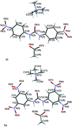
:![[thin space (1/6-em)]](https://www.rsc.org/images/entities/char_2009.gif) 2. In this case the asymmetric unit consists of half a TMA, half a fluoride and one para substituted receptor molecule. A consistent labelling scheme for the atoms has been used for all structures and is shown in Fig. 2.
2. In this case the asymmetric unit consists of half a TMA, half a fluoride and one para substituted receptor molecule. A consistent labelling scheme for the atoms has been used for all structures and is shown in Fig. 2.
The anion complexed varies from chloride (4 and 7) to acetate (5 and 8) to fluoride (6), the substitution pattern of the phenyl ring is also varied – meta (7), para (4, 5 and 6) and 3,5-dinitro (8). However, throughout the family of structures some common features are retained, for example the TMA cation is present in all 5 structures. The common structural elements such as the TMA cation and phenyl rings should not be greatly perturbed by changes in the substitution pattern or anion. These groups can act as internal standards and provide validation of the quality and consistency of the multipole modelling. Below the properties of these common structural elements are briefly described and are consistent with this hypothesis.
In each complex the TMA group has an overall positive charge (0.02–0.75 e) and the anion a negative charge (−0.29–−0.68 e). The low positive charge of the TMA in 6 (0.02 e) compared to the other structures may be due to modelling this group using the Invariom approach, or its differing position in the crystal structure compared to the other structures.
The electronic properties at the bond critical points (BCPs) can be used to characterise the bonds between atoms. In each of the structures these values are consistent with those expected for the differing types of covalent interactions expected to be present in the systems from geometrical considerations. Generally, single bonds were shown to have electron density (ρ(rBCP)) and Laplacian of the electron density (∇2ρ(rBCP)) values of ∼1.80 e Å−3 and −15.00 e Å−5 respectively, while those of C![[double bond, length as m-dash]](https://www.rsc.org/images/entities/char_e001.gif) C aromatic bonds were generally >2.00 e Å−3 and −17.00 e Å−5 respectively, and hetero C
C aromatic bonds were generally >2.00 e Å−3 and −17.00 e Å−5 respectively, and hetero C![[double bond, length as m-dash]](https://www.rsc.org/images/entities/char_e001.gif) O double bonds ∼3.00 e Å−3 and −40.00 e Å−5 respectively. The conjugated, aromatic nature of the bonds in the phenyl rings is supported by the high bond ellipticity values, which were between 0.06 and 0.33 at the BCPs in the C–C bonds, and the profile of the bond ellipticity along the bond path (see ESI†). These are similar across the five structures apart from in 8 where the additional nitro groups and their increased electron-withdrawing effect seems to perturb the electron density in the aromatic region sufficiently to alter the bond ellipticity profile along the aromatic bond paths.
O double bonds ∼3.00 e Å−3 and −40.00 e Å−5 respectively. The conjugated, aromatic nature of the bonds in the phenyl rings is supported by the high bond ellipticity values, which were between 0.06 and 0.33 at the BCPs in the C–C bonds, and the profile of the bond ellipticity along the bond path (see ESI†). These are similar across the five structures apart from in 8 where the additional nitro groups and their increased electron-withdrawing effect seems to perturb the electron density in the aromatic region sufficiently to alter the bond ellipticity profile along the aromatic bond paths.
Though the charges on the phenyl ring carbon atoms in all the structures vary, C(4) and C(8), the atoms connected to the urea group, are generally the most positive phenyl ring atoms in each structure and the carbons to which the nitro groups are attached, are also all positively charged (apart from one of these atoms in 8) due to the inductive (−I) electron-withdrawing effect of these groups. The positions and interactions of the TMA cation relative to the receptor in 4, 5 and 6 vary across the series (constant para receptor with different anion), particularly that of the TMA cation in the fluoride structure 6, however the range of the ρ(rBCP) and ∇2ρ(rBCP) values at the C–N BCPs are consistent with those reported by Munshi et al. in the related tetramethylalkyldiammonium salt.76 In 6 the multipole populations for TMA were taken from the Invariom database enabling the modelling of the electron density of this region, however the similarity of the properties of the ρ(rBCP) at the BCPs in 6 with those across the series of structures in this paper and with the literature suggest that this is an acceptable model for the group. As expected with no alteration in the cation between structures 4 (para chloride complex) and 7 (meta chloride complex), and a similar position and interaction environment in both, the properties of the BCPs between the TMA nitrogen atom and methyl carbons, N(5)–C(14/15/16/17) do not vary significantly in 4 and 7. Such agreement in the properties at the TMA group C–N BCPs was also noted between 5 (para acetate complex) and 8 (dinitro acetate complex). Properties of the urea group display more variation across the series of complexes and appear to be a result of both anion changes and modification of the receptor. This was envisaged when designing the comparison system and these differences will be discussed in greater detail.
Variation of the anion
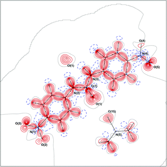
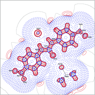
Studying complexes of 1,3-bis(4-nitrophenyl)urea (1) and changing the anion from chloride to acetate to fluoride (4vs.5vs.6), enables the variations in the electron density distributions across the crystal structures to be related to the basicity of the anion, Cl− < −OAc < F−. The charge density distribution in the crystal structure of 4 is displayed in Fig. 3 and 4 (static deformation charge density distribution plot and negative Laplacian charge density distribution map respectively, both plotted in the plane of the urea molecule).The static deformation density (the difference between the multipole model density and the independent atom model, with the effects of thermal smearing removed) highlights areas where the electron density deviates from a spherical atom model, such as lone pairs and the bonding interactions between atoms. Fig. 3 displays some of these features for 4, bonding density between the carbon atoms of the phenyl rings, the areas of negative electron density corresponding to the shift in the electron density of the hydrogen atoms into the bonding region and the lone pairs of the urea oxygen atoms. In Fig. 4, which amplifies the variation in the electron density distribution–accumulation and depletion of charge, again illustrates the lone pairs of the urea oxygen atom and chloride anion and bonding interactions in 4. The similarity with plots of the remaining crystal structures (ESI†) show common regions of the structures (e.g. the phenyl rings) have comparable electron density distributions.
![[thin space (1/6-em)]](https://www.rsc.org/images/entities/char_2009.gif) :
:![[thin space (1/6-em)]](https://www.rsc.org/images/entities/char_2009.gif) 1 stoichiometry in solution, which agrees with the anion to receptor ratio seen in the solid-state in structures 4 and 5, but not with that observed for 6, which has a 1
1 stoichiometry in solution, which agrees with the anion to receptor ratio seen in the solid-state in structures 4 and 5, but not with that observed for 6, which has a 1![[thin space (1/6-em)]](https://www.rsc.org/images/entities/char_2009.gif) :
:![[thin space (1/6-em)]](https://www.rsc.org/images/entities/char_2009.gif) 2 anion to receptor ratio in the solid-state. However in contrast to the behaviour observed in the solid-state with fluoride, in solution receptor 1 appears to be deprotonated by this basic anion with the disappearance of the N–H resonance upon addition of fluoride (see ESI†) accompanied by a distinct colour change from yellow to orange. This behaviour has been previously noted by Boiocchi et al.77 who reported the deprotonation of 1 by fluoride in UV-Vis titration studies in acetonitrile. In this study the strongest binding constant of receptor 1 with the three anions obtained was of that with acetate, which was >104 M−1, indicative of strong binding in solution, while the affinity for chloride (118 M−1) was markedly weaker.19
2 anion to receptor ratio in the solid-state. However in contrast to the behaviour observed in the solid-state with fluoride, in solution receptor 1 appears to be deprotonated by this basic anion with the disappearance of the N–H resonance upon addition of fluoride (see ESI†) accompanied by a distinct colour change from yellow to orange. This behaviour has been previously noted by Boiocchi et al.77 who reported the deprotonation of 1 by fluoride in UV-Vis titration studies in acetonitrile. In this study the strongest binding constant of receptor 1 with the three anions obtained was of that with acetate, which was >104 M−1, indicative of strong binding in solution, while the affinity for chloride (118 M−1) was markedly weaker.19
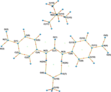 | ||
| Fig. 5 Molecular graph of 5 displaying the nuclear positions (blue), bond paths (yellow) and the BCPs (red). | ||
| D–H⋯A | BCP H⋯A | ρ(rBCP) (e Å−3) | ∇2ρ(rBCP) (e Å−5) | R ij H⋯A (Å) | A–BCP distance (Å) | H–BCP distance (Å) | D–BCP distance (Å) | G(rBCP) (a.u.) | V(rBCP) (a.u.) | |V(rBCP)|/G(rBCP) | E HB (kJ mol−1) | H(rBCP) (kJ mol−1) |
|---|---|---|---|---|---|---|---|---|---|---|---|---|
| 4. Para receptor with chloride | ||||||||||||
| N(2)–H(2A) ⋯Cl(1) | H(2A)⋯Cl(1) | 0.120(1) | 1.949(4) | 2.2423 | 1.4656 | 0.7767 | 1.7449 | 0.017 | −0.014 | 0.808 | −17.980 | 8.561 |
| N(3)–H(3A) ⋯Cl(1) | H(3A)⋯Cl(1) | 0.125(2) | 2.319(7) | 2.1854 | 1.4562 | 0.7292 | 1.7056 | 0.020 | −0.016 | 0.783 | −20.303 | 11.277 |
| 5. Para receptor with acetate | ||||||||||||
| N(2)–H(2A) ⋯O(6) | H(2A)⋯O(6) | 0.191(3) | 4.19(3) | 1.7647 | 1.1783 | 0.5863 | 1.6283 | 0.037 | −0.030 | 0.810 | −38.855 | 18.258 |
| N(3)–H(3A) ⋯O(7) | H(3A)⋯O(7) | 0.313(3) | 4.29(3) | 1.6905 | 1.1022 | 0.5883 | 1.6314 | 0.047 | −0.049 | 1.051 | −64.595 | −6.230 |
| C(3)–H(3) ⋯O(6) | H(3)⋯O(6) | 0.061(6) | 1.055(2) | 2.4065 | 1.4295 | 0.9971 | — | 0.008 | −0.006 | 0.701 | −7.746 | 6.621 |
| C(9)–H(9) ⋯O(7) | H(9)⋯O(7) | 0.080(6) | 1.225(2) | 2.3356 | 1.3879 | 0.9476 | — | 0.010 | −0.008 | 0.759 | −10.207 | 6.475 |
| 6. Para receptor with fluoride | ||||||||||||
| N(2)–H(2A) ⋯F(1) | H(2A)⋯F(1) | 0.256(2) | 4.27(2) | 1.7244 | 1.0994 | 0.6250 | 1.5981 | 0.042 | −0.039 | 0.941 | −51.681 | 6.494 |
| N(3)–H(3A) ⋯F(1) | H(3A)⋯F(1) | 0.279(2) | 4.94(2) | 1.6766 | 1.0701 | 0.6065 | 1.5680 | 0.048 | −0.046 | 0.940 | −59.696 | 7.589 |
| 7. Meta receptor with chloride | ||||||||||||
| N(2)–H(2A) ⋯Cl(1) | H(2A)⋯Cl(1) | 0.129(2) | 2.28(1) | 2.2201 | 1.5093 | 0.7108 | 1.6797 | 0.020 | −0.016 | 0.800 | −20.635 | 10.359 |
| N(3)–H(3A) ⋯Cl(1) | H(3A)⋯Cl(1) | 0.152(2) | 2.43(1) | 2.1518 | 1.4400 | 0.7117 | 1.6898 | 0.022 | −0.019 | 0.853 | −24.565 | 8.499 |
| 8. Dinitro receptor with acetate | ||||||||||||
| N(3)–H(3A) ⋯O(10) | H(3A)⋯O(10) | 0.318(4) | 4.19(3) | 1.7359 | 1.0932 | 0.6426 | 1.6495 | 0.047 | −0.050 | 1.068 | −65.377 | −8.291 |
| N(4)–H(4A) ⋯O(11) | H(4A)⋯O(11) | 0.353(4) | 3.92 (4) | 1.6774 | 1.0889 | 0.5884 | 1.593 | 0.048 | −0.056 | 1.155 | −72.957 | −19.562 |
Plots of the average ρ(rBCP) and ∇2ρ(rBCP) for the N–H⋯anion hydrogen bonds for each complex of 1 against the pKas of the anion are shown in Fig. 7 and 8 respectively and illustrate the increase in hydrogen bond strength as basicity increases. This increase in electron density at the BCPs as basicity increases indicates a stronger interaction and matches the observed binding affinities in solution where chloride was shown to have a markedly weaker association with receptor 1 than acetate.
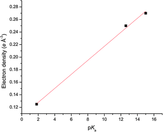 | ||
| Fig. 7 Linear relationship (R2 of the linear fit is 0.996) between the electron density (units of e Å−3) at the hydrogen bonding BCPs and the pKa of the anion in 4, 5 and 6. | ||
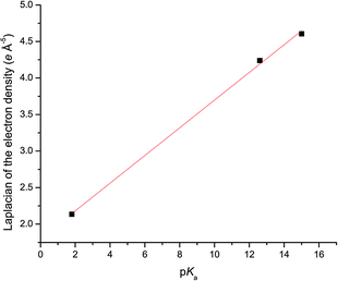 | ||
| Fig. 8 Linear relationship (R2 of the linear fit is 0.998) between the laplacian of the electron density (units of e Å−5) at the hydrogen bonding BCPs and the pKa of the anion in 4, 5 and 6. | ||
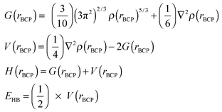
The nature of the hydrogen bonding interaction, i.e. whether it is electrostatic or covalent is a source of debate in many systems similar to this and can be determined in charge density by analysing the properties of the electron density at the BCPs.81 The energetic properties; the local kinetic energy density, G(rBCP), the local potential energy density, V(rBCP), the total energy density, H(rBCP), and the hydrogen bond energy, EHB are indicators of hydrogen bond nature and these have been calculated for the hydrogen bonds in this series using eqn (2).82
 | (2) |
The exponential relationship of both ρ(rBCP) and ∇2ρ(rBCP) with the H⋯A distance has previously been noted in charge density studies of hydrogen bonding.5,6,83 Similar exponential relationships exist in this study, as illustrated in Fig. 9, which plots the exponential relationship between H⋯A distance and the electron density at the BCP in this family of anion receptor complexes. Espinosa and co-workers have shown in multiple studies on X–H⋯O interactions that geometric parameters of hydrogen bonds can be correlated to the topology of ρ(rBCP) in the hydrogen bonding region, which itself is intrinsically linked to the energetic properties at the BCP.83–85 The exponential relationship observed between the H⋯A distance and both V(rBCP) and G(rBCP) has also been rationalised.86
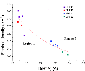 | ||
| Fig. 9 Exponential relationship between ρ(rBCP) and the H⋯A distance. The two regions of hydrogen bond interaction are shown. | ||
As increases in ρ(rBCP) and ∇2ρ(rBCP) are both an indication of increasing hydrogen bond strength these exponential relationships suggest the suitability of estimating the relative hydrogen bond strengths from DHA distances (the combined hydrogen bond donor, hydrogen atom and hydrogen bond acceptor atom distance) a typical approach used to quantify hydrogen bonding in atomic resolution structural studies of anion receptor complexes, in this series of structures.
In this series two distinct types of hydrogen bonding (Fig. 9) are observed. Region 1, an area of stronger hydrogen bonding, contains the N–H⋯anion hydrogen bonds of the fluoride and acetate complexes (5, 6, and 8) and is characterised by electron density values at the BCPs >0.19 e Å−3 and H⋯A distances <1.80 Å with the bond path between the D⋯A atoms shorter than the van der Waals radii of the individual atoms. Region 2 is a weaker hydrogen bonding area with the electron density at the BCPs <0.15 e Å−3 and the H⋯A distance >2.15 Å and encompasses the N–H⋯Cl interactions of the chloride structures (4 and 7) and the C–H⋯O interactions in 5. In these interactions the sum of the van der Waals radii of the interacting atoms is lower than the bond path between the D⋯A atoms. Across 4, 5 and 6 the profiles of the ∇2ρ(rBCP) and bond ellipticity along the urea group bond paths are similar due to the common nature of the receptor (see ESI†).
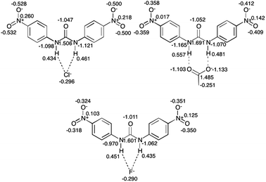 | ||
| Fig. 10 Integrated charges (units e) in key areas of the para substituted receptor structures 4 (chloride), 5 (acetate) and 6 (fluoride). | ||
The acetate oxygen atoms in 5 are highly negative, while the halide anions in 4 and 6 have less negative charge. The higher charges observed for the acetate anions (5 and 8) compared to the halide anions may be due to the different nature of the hydrogen bonding outlined above, where the acetate anions are involved in hydrogen bonding of a possibly partially covalent nature or boundary nature (as suggested by the |V(rBCP)/G(rBCP)| ratio greater than 1 and the H(rBCP) less than zero).5
From 4 to 6, as the basicity of the anion increases, the charges of the urea nitrogen atoms become less negative. This perturbation of charge in the urea portion of the structures is shown to extend to the peripheral regions of the structure with the charge on the oxygen atoms of the nitro groups approaching closer to neutrality with increasing basicity. This is reflected in the changes in the electrostatic potential distribution of these regions displayed in Fig. 11.
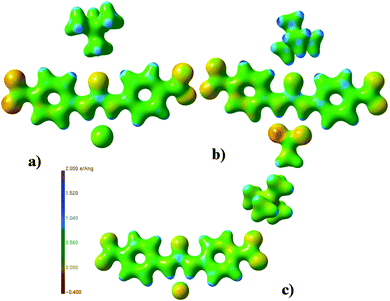 | ||
| Fig. 11 Electrostatic potential plots87 (units e Å−1) of (a) 4, (b) 5 and (c) 6. | ||
The substituent positional effect
This family of structures offers a further comparison through varying receptors and maintaining a given anion. The effect of peripheral modification of the receptor on the electron density distribution is analysed by comparing two sets of structures where a common anion is complexed to a different receptor scaffold. Altering the location of the nitro group in receptor 1 from the para to the meta position in receptor 2 allows an investigation into the effect of the different electron-withdrawing abilities of nitro groups in different positions. Complexes 4 and 7 (the chloride complexes of para receptor 1 and meta receptor 2 respectively) only vary in the position of the nitro groups. The effect of further increasing the electron-withdrawing nature of the substituent positioned on the phenyl rings of the receptor scaffold can be probed by comparison with the 1,3-bis(3,5-di-nitrophenyl)urea receptor (3), which has two nitro groups on each phenyl ring and is therefore expected to cause a greater pull of electrons away from the urea and phenyl rings onto the nitro groups. Contrasting the two acetate complexes allows a comparison of the effect of dinitro (8) and para (5) substitution of the receptor on the electron density distribution.Fig. 9 shows that in each set of comparison structures (4vs.7 and 5vs.8) the interactions of each class of hydrogen bond, N–H⋯Cl (found in 4 and 7) and N–H⋯O (5 and 8) lie in the same region, those of the chloride structures in region 2, that of weak hydrogen bonding, and those of the acetate structures in region 1, the strong hydrogen bond region.
In the chloride complexes 4 and 7 (with para and meta substituted receptors respectively), the values of ρ(rBCP), ∇2ρ(rBCP), G(rBCP), V(rBCP), and H(rBCP) at the observed N–H⋯Cl BCPs are consistent with classification of the hydrogen bonding as weak (as outlined by Rozas et al., both ∇2ρ(rBCP) and H(rBCP) > 0).81 Although as anticipated 4 and 7 (para vs. meta chloride) exhibit the same type of hydrogen bonding interaction, there is variation between the values of the ρ(rBCP) and ∇2ρ(rBCP) of the N–H⋯Cl in 4 and 7, which is higher than the estimated standard uncertainties on these values, and the higher values observed in 7 suggests its hydrogen bonds are stronger.
In the acetate complexes (5 and 8, where the receptor is para-nitro and 3,5-dinitro substituted respectively) the distance between the atoms involved in the N–H⋯anion hydrogen bonding is shorter than the van der Waals radii of the atoms. Properties of the electron density at the BCPs of the hydrogen bonds, shown in Table 2, suggest that two differing types of hydrogen bonding interactions are present in these structures. The lower ρ(rBCP) and ∇2ρ(rBCP) values for the N–H⋯anion BCPs in 5 characterise weaker strength hydrogen bonding in this structure, compared to those interactions in 8.81 Using the source function approach,88–90 it is possible to calculate how different regions of the structure contribute to the electron density at a BCP. The combined contribution of the DHA atoms to the electron density at the hydrogen bond BCPs support the weaker hydrogen bonding in 5 compared to 8, with the contribution greater from the DHA atoms in 8 than 5. (The full source function analysis is shown in Table 3 below.) The value of H(rBCP) and |V(rBCP)|/G(rBCP) for the N–H(3A)⋯O(7) BCPs in 5 and N–H(3A)⋯O(10) and H(4A)⋯O(11) BCPs in 8 (shown in Table 2) suggest these are medium strength boundary type hydrogen bonds unlike the weaker purely electrostatic hydrogen bonding interactions found in the other structures. This may be due to the geometry of the anion in the acetate structures (5 and 8), where there is a more linear arrangement of the hydrogen bond, with each urea N–H hydrogen bond donor group forming a hydrogen bond atom with one of the oxygen atoms of the acetate, while in the halide structures (4, 6 and 7) the anion has bifurcated hydrogen bonds. In the acetate complexes (para-nitro 5 and 3,5-dinitro 8) the shorter hydrogen bonds correspond to medium strength intermediate type interactions.
| Hydrogen bond | Donor (%) | Acceptor (%) | Hydrogen (%) | Sum of DHA (%) |
|---|---|---|---|---|
| 4. Para receptor with chloride | ||||
| N(2)⋯Cl(1) | 49.05 | 53.67 | −51.58 | 51.14 |
| N(3)⋯Cl(1) | 50.73 | 55.93 | −56.10 | 50.56 |
| 5. Para receptor with acetate | ||||
| N(2)⋯O(6) | 38.64 | 13.06 | −28.36 | 23.34 |
| N(3)⋯O(7) | 21.90 | 28.53 | 2.78 | 53.21 |
| 6. Para receptor with fluoride | ||||
| N(2)⋯F(1) | 29.33 | 48.45 | −9.27 | 68.51 |
| N(3)⋯F(1) | 28.50 | 44.50 | −7.09 | 65.91 |
| 7. Meta receptor with chloride | ||||
| N(2)⋯Cl(1) | 47.20 | 52.81 | −48.46 | 51.55 |
| N(3)⋯Cl(1) | 40.99 | 52.66 | −38.02 | 55.63 |
| 8. Dinitro receptor with acetate | ||||
| N(3)⋯O(10) | 19.98 | 27.53 | 3.19 | 50.70 |
| N(4)⋯O(11) | 21.30 | 37.11 | 8.46 | 66.87 |
There is a disparity between the solid-state and solution phase observations, as topological analysis of the electron density at the BCPs of the N–H⋯Cl interactions in 4 and 7 (para and meta chloride complexes respectively) suggests 7 has marginally stronger hydrogen bonds, while in solution the para substituted receptor (1) was shown to have stronger affinity for chloride than the meta substituted receptor (2), 118 vs. 56 M−1. This may be caused by additional non-covalent interactions between other components of the structure, such as TMA⋯nitro contacts, in the solid-state that promote stronger association between receptor 2 and chloride in the crystalline environment. In 8 there is no evidence to support the deprotonation of the receptor by acetate suggested in solution, so the interactions in solution and the solid-state cannot be directly compared in this case.
While the classification of the two chloride structures (4 and 7) confirms the same nature of interaction, more variation is observed between the two acetate complexes (5 and 8). The contribution the hydrogen atoms make to the electron density at the BCPs in the hydrogen bonds present in the halide complexes (structures 4, 6 and 7) has been quantified using the source function approach88–90 and found to be negative. Therefore the hydrogen atoms act as electron density “sinks”, implying that the hydrogen bonds are electrostatic in nature. This behaviour is not observed in 5 and 8, where the hydrogen atoms act as “sources” for the electron density at the N–H⋯O hydrogen bonds, providing a positive contribution, which suggests a stronger interaction. According to Gilli & Gilli's classifications these N–H⋯O hydrogen bonds, are resonance assisted hydrogen bonds.91 The halide N–H⋯anion hydrogen bonds in the series are, according to the same classification, polarised assisted hydrogen bonds. This is not just a result of the anion type, as in 5 only one of the hydrogen atoms of the N–H bonds is a “source” and the other a “sink” for the electron density. Contrastingly in 8 both hydrogen atoms are “sources” for the electron density, suggesting this effect is related to the additional nitro groups enhancing the acidity of the N–H bond and strengthening the association between the host and the guest. This is an interesting example of how changes in the electron density distribution at particular areas of interest in the structures are caused by peripheral modifications. It also demonstrates how a systematic approach best reveals these effects.
In the two acetate complexes (5 and 8, with para-nitro and 3,5-dinitro substituted receptors respectively) geometric analysis reveals the presence of C–H⋯O interactions between the phenyl ring hydrogen atoms and acetate oxygen atoms (with H⋯A distances and DHA angles in 5 of 2.381 Å 136.86° and 2.305 Å 134.58° and in 8 of 2.535 Å 130.69° and 2.355 Å 131.72°). These fulfil the geometric standards set out by Wood et al.,92 (building on previous work93,94) in their study on hydrogen bonding using the Cambridge Structural Database95 where D–H⋯A angles <120° were ruled out as hydrogen bonding interactions. However, bond paths between the respective H⋯A atoms are present in 5 while in 8 they are not. This is a powerful example of how systematic charge density analysis provides key information, as it is necessary to determine if an interaction is ‘real’ or an erroneous assumption based on geometry. Additionally, this work demonstrates how modification of the receptor scaffold in this case has brought about changes in the intermolecular interactions observed in the crystal structure, as altering the receptor substitution pattern from para (5) to dinitro (8) is accompanied by a change of the acetate anion from co-planarity with the receptor in 5 to non co-planarity of the acetate and receptor in 8.
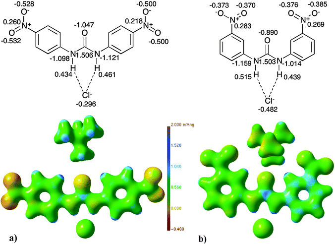 | ||
| Fig. 12 Electrostatic potential maps87 (units of e Å−1) and selected QTAIM charges (units of e) of (a) 4versus (b) 7. | ||
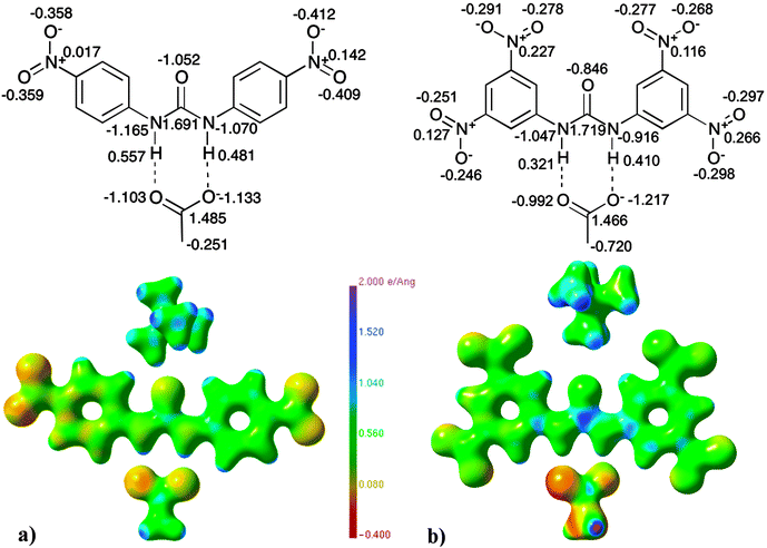 | ||
| Fig. 13 Electrostatic potential maps87 (units of e Å−1) and selected QTAIM charges (units of e) of (a) 5versus (b) 8. | ||
When altering the receptor substituent pattern as in 4vs.7 and 5 and 8 electrostatic potential distributions vary significantly across the entire structures. In Fig. 12 the urea and phenyl ring areas of 7 display a greater positive electrostatic potential as compared to structure 4. The nitro groups in 4, which are para substituted, have a more negative electrostatic potential than those in 7, where they are in the meta position, as predicted due to the greater electron-withdrawing ability of nitro groups in the para position.
When comparing the structure of the para substituted receptor with acetate, 5 and the acetate complex of the dinitro substituted receptor 8 (Fig. 13), major deviations in the electrostatic potential distribution of the acetate anion are detected. The acetate in structure 8 is carrying a greater negative electrostatic potential than the acetate in 5. The electrostatic potential of the urea portion of the receptor in 8 is shown to have a larger variation than in 5, with a higher positive electrostatic potential on the carbon atom of the urea. This matches the increase in hydrogen bond strength from 5 to 8. The nitro groups of the para substituted complex (5) are shown to have a more negative electrostatic potential than those in 8, where they are situated in both the 3 and 5 positions of the phenyl rings. This could be explained by the electron-withdrawing effect of the nitro groups, (which is greater in 8), exerted on the urea group being spread over a larger number of nitro groups than in structure 5. This causes the less negative electrostatic potential distribution on the individual nitro groups but an overall greater contrast in electrostatic potential distribution of the urea region in 8 compared to 5.
The differences observed in the electrostatic potential distribution can be correlated to the charges calculated using QTAIM theory (displayed graphically with the electrostatic potential plots in Fig. 12 and 13). In both comparison sets the charge of the anion is seen to differ. The charge associated with chloride in 4 (−0.296 e) is less negative than that of chloride in 7 (−0.482 e). The acetate anion complexes have QTAIM charges for the oxygen atoms that are, as expected, highly negative (∼1.00 e), however the difference is larger in 8 than 5. The increase in the charge of the anion may be responsible for the observed increase in the electrostatic contribution to the anion: receptor interaction between 4 and 7 and 5 and 8.
Due to the differences in the receptor pattern (para vs. meta receptor both complexed to chloride in 4 and 7 and para-nitro vs. 3,5-dinitro with the acetate anion common in 5 and 8) the electronic distribution alters in the urea region of the receptor and this is observed in the variation of charges for these atoms (see Fig. 12 and 13). Variation in the electrostatic potential distribution of the nitro groups is also reflected in the difference in charges of the individual atoms present in the nitro groups.
Of further note is the difference in the properties of the C–N BCPs linking the nitro groups to the phenyl ring for a given anion. While the properties in 8 are similar to those observed in 5, the values of the electron density and Laplacian of the electron density at the BCPs in the meta complex, 7, between C(6)–N(1) and C(12)–N(4) are lower than the values observed in 4. These match those of 5 and 6, suggesting this is a result of altering the location of the nitro group from the para to meta position. This is linked to the difference observed in the ∇2ρ(rBCP) and bond ellipticity profiles along the bond paths of the urea region of the structures (see ESI†). In 7 and 8 the profiles of these bond paths contrast markedly to those in 4, 5 and 6, suggesting the changes are a result of the altering electron-withdrawing nature of the nitro groups in varying positions on the phenyl rings, effecting the electron density distribution in the urea region to a lesser or greater extent. These may also reflect a difference between the mesomeric electron-withdrawing effects possible in the para series of complexes (4–5–6) with the inductive electron-withdrawing effects (7 and 8).
Changes to particular regions of the receptor scaffold have been shown to have an observable effect on the electron density distribution across the entire structure, not just the immediate area of substitution. Variation in charge, the properties of the electron density at the BCPs, and the electrostatic potential distribution are evident across our family of structures.
Additional non-covalent interactions
![[double bond, length as m-dash]](https://www.rsc.org/images/entities/b_char_e001.gif) C.
Topological analysis highlighted the presence of intermolecular interactions between the C–H bonds of the TMA cation and urea oxygen atom in all five structures, excluding 6, due to the different position of the TMA cation in 6. These are weak closed-shell interactions, evidenced by the low electron density values and low positive values of the ∇2ρ(rBCP) at the BCPs (see Table 4). The nature of these interactions varies between the structures, with multiple carbon and hydrogen atoms of the TMA groups involved in the interactions in 4 and 7, while in 5 and 8 only one carbon of the TMA cation is involved in these interactions. Additionally, in structures 4, 5 and 7 CH⋯C interactions between the phenyl rings of the receptor molecule and carbon atoms of TMA are noted.
C.
Topological analysis highlighted the presence of intermolecular interactions between the C–H bonds of the TMA cation and urea oxygen atom in all five structures, excluding 6, due to the different position of the TMA cation in 6. These are weak closed-shell interactions, evidenced by the low electron density values and low positive values of the ∇2ρ(rBCP) at the BCPs (see Table 4). The nature of these interactions varies between the structures, with multiple carbon and hydrogen atoms of the TMA groups involved in the interactions in 4 and 7, while in 5 and 8 only one carbon of the TMA cation is involved in these interactions. Additionally, in structures 4, 5 and 7 CH⋯C interactions between the phenyl rings of the receptor molecule and carbon atoms of TMA are noted.
| Critical point | ρ(rBCP) (e Å−3) | ∇2ρ(rBCP) (e Å−5) | R ij (Å) | d 1 (A–CP) (Å) | d 2 (CP–B) (Å) | ε | Type |
|---|---|---|---|---|---|---|---|
TMA⋯C![[double bond, length as m-dash]](https://www.rsc.org/images/entities/char_e001.gif) O O |
|||||||
| 4. Para receptor with chloride | |||||||
| O(1)⋯C(15) | 0.056(2) | 0.912(1) | 2.9490 | 1.4398 | 1.5092 | 2.32 | BCP |
| O(1)⋯H(15A) | 0.056(2) | 0.912(1) | 2.7784 | 1.4398 | 1.3386 | 2.32 | BCP |
| O(1)⋯H(15C) | 0.056(2) | 0.912(1) | 2.9622 | 1.4398 | 1.5224 | 2.32 | BCP |
| 5. Para receptor with acetate | |||||||
| O(1)⋯H(14C) | 0.039(5) | 0.654(2) | 2.5792 | 1.5001 | 1.0791 | 0.29 | BCP |
| O(1)⋯H(17C) | 0.067(9) | 1.166(2) | 2.3469 | 1.4107 | 0.9361 | 0.08 | BCP |
| 7. Meta receptor with chloride | |||||||
| O(1)⋯C(15) | 0.050(3) | 0.776(2) | 3.2739 | 1.4364 | 1.8376 | 0.08 | BCP |
| O(1)⋯C(17) | 0.046(2) | 0.714(2) | 3.2809 | 1.4636 | 1.8173 | 0.13 | BCP |
| O(1)⋯H(15C) | 0.050(3) | 0.776(2) | 2.5618 | 1.4364 | 1.1254 | 0.08 | BCP |
| O(1)⋯H(17C) | 0.046(2) | 0.714(2) | 2.6562 | 1.4636 | 1.1926 | 0.13 | BCP |
| 8. Dinitro receptor with acetate | |||||||
| O(1)⋯C(16) | 0.057(2) | 0.774(2) | 3.0395 | 1.4455 | 1.5941 | 0.09 | BCP |
| O(1)⋯H(16C) | 0.057(2) | 0.774(2) | 2.8178 | 1.4455 | 1.3723 | 0.09 | BCP |
| TMA⋯H–C | |||||||
| 4. Para receptor with chloride | |||||||
| C(15)⋯H(5) | 0.001(3) | 0.194(2) | 3.4145 | 2.2495 | 1.1650 | 0.00 | RCP |
| 5. Para receptor with acetate | |||||||
| C(17)⋯H(5) | 0.037(3) | 0.549(1) | 2.9070 | 1.7910 | 1.1160 | 1.92 | BCP |
| 7. Meta receptor with chloride | |||||||
| C(15)⋯H(13) | 0.023(5) | 0.440(3) | 3.2298 | 2.0690 | 1.1608 | 0.57 | BCP |
| C(17)⋯H(13) | 0.005(4) | 0.194(2) | 3.4817 | 2.2654 | 1.2163 | 0.00 | RCP |
![[double bond, length as m-dash]](https://www.rsc.org/images/entities/b_char_e001.gif) C.
In each of the structures intramolecular hydrogen bonds between the urea group oxygen atom and both the aromatic C–H bonds ortho to the urea are characterised by bond paths and BCPs between C(5)⋯O(1) and C(13)⋯O(1). These are accompanied by bond paths between the hydrogen atoms of these carbons and the oxygen atoms (H(5)⋯O(1) and H(13)⋯O(1)). The length of both the bond paths between the hydrogen atoms and carbon atoms (<2.90 Å) and the carbon atoms and oxygen atoms (<3.22 Å) are less than the van der Waals radii of the atoms. In addition the values of the electron density and the Laplacian of the electron density at the BCPs (Table 5) suggest that there is a combination of weak C–H⋯O and ‘carbon bonding’, initially described in theoretical studies by Mani and Arunan96 and observed experimentally in charge density studies by Thomas et al.97 The presence of a ring critical point between both C(4) and O(1) and C(8) and O(1) in each of the structures also emphasizes the interaction between the urea and phenyl rings, and suggests the presence of a six-membered ring.
C.
In each of the structures intramolecular hydrogen bonds between the urea group oxygen atom and both the aromatic C–H bonds ortho to the urea are characterised by bond paths and BCPs between C(5)⋯O(1) and C(13)⋯O(1). These are accompanied by bond paths between the hydrogen atoms of these carbons and the oxygen atoms (H(5)⋯O(1) and H(13)⋯O(1)). The length of both the bond paths between the hydrogen atoms and carbon atoms (<2.90 Å) and the carbon atoms and oxygen atoms (<3.22 Å) are less than the van der Waals radii of the atoms. In addition the values of the electron density and the Laplacian of the electron density at the BCPs (Table 5) suggest that there is a combination of weak C–H⋯O and ‘carbon bonding’, initially described in theoretical studies by Mani and Arunan96 and observed experimentally in charge density studies by Thomas et al.97 The presence of a ring critical point between both C(4) and O(1) and C(8) and O(1) in each of the structures also emphasizes the interaction between the urea and phenyl rings, and suggests the presence of a six-membered ring.
![[double bond, length as m-dash]](https://www.rsc.org/images/entities/char_e001.gif) C interactions in phenyl groups of structures
C interactions in phenyl groups of structures
| Critical point | ρ(rBCP) (e Å−3) | ∇2ρ(rBCP) (e Å−5) | R ij (Å) | d 1 (A–CP) (Å) | d 2 (CP–B) (Å) | ε | Type |
|---|---|---|---|---|---|---|---|
| 4. Para receptor with chloride | |||||||
| O(1)⋯C(4) | 0.085(2) | 1.446(2) | 3.0360 | 1.4545 | 1.5814 | 0.00 | RCP |
| O(1)⋯C(8) | 0.085(2) | 1.430(2) | 3.0469 | 1.4463 | 1.6006 | 0.00 | RCP |
| O(1)⋯C(5) | 0.106(2) | 1.635(2) | 2.9214 | 1.3294 | 1.5920 | 0.11 | BCP |
| O(1)⋯C(13) | 0.106(3) | 1.670(2) | 2.9299 | 1.3212 | 1.6088 | 0.08 | BCP |
| 5. Para receptor with acetate | |||||||
| O(1)⋯C(4) | 0.105(3) | 1.620(2) | 2.9868 | 1.4270 | 1.5598 | 0.00 | RCP |
| O(1)⋯C(8) | 0.102(3) | 1.571(2) | 3.0076 | 1.4197 | 1.5879 | 0.00 | RCP |
| O(1)⋯C(5) | 0.132(4) | 1.970(3) | 2.8631 | 1.2804 | 1.5827 | 0.09 | BCP |
| O(1)⋯C(13) | 0.124(4) | 1.833(2) | 2.8907 | 1.3125 | 1.5782 | 0.13 | BCP |
| 6. Para receptor with fluoride | |||||||
| O(1)⋯C(4) | 0.103(2) | 1.500(2) | 3.0795 | 1.4170 | 1.6625 | 0.00 | RCP |
| O(1)⋯C(8) | 0.097(2) | 1.403(1) | 3.1073 | 1.4252 | 1.6821 | 0.00 | RCP |
| O(1)⋯C(5) | 0.115(3) | 1.710(2) | 2.9339 | 1.3123 | 1.6216 | 0.35 | BCP |
| O(1)⋯C(13) | 0.102(2) | 1.492(2) | 2.9367 | 1.3443 | 1.5923 | 0.57 | BCP |
| 7. Meta receptor with chloride | |||||||
| O(1)⋯C(4) | 0.102(3) | 1.584(2) | 3.0287 | 1.4126 | 1.6161 | 0.00 | RCP |
| O(1)⋯C(8) | 0.102(3) | 1.574(2) | 3.0197 | 1.4135 | 1.6062 | 0.00 | RCP |
| O(1)⋯C(5) | 0.124(4) | 1.834(2) | 2.8991 | 1.3058 | 1.5933 | 0.24 | BCP |
| O(1)⋯C(13) | 0.120(4) | 1.806(2) | 2.8714 | 1.2995 | 1.5719 | 0.16 | BCP |
| 8. Dinitro receptor with acetate | |||||||
| O(1)⋯C(4) | 0.125(3) | 1.783(3) | 2.9855 | 1.3720 | 1.6135 | 0.00 | RCP |
| O(1)⋯C(8) | 0.125(3) | 1.756(3) | 2.9864 | 1.3966 | 1.5899 | 0.00 | RCP |
| O(1)⋯C(5) | 0.143(4) | 2.005(3) | 2.8321 | 1.2842 | 1.5479 | 0.48 | BCP |
| O(1)⋯C(13) | 0.142(3) | 2.007(3) | 2.8471 | 1.2868 | 1.5604 | 0.47 | BCP |
| Critical point | ρ(rBCP) (e Å−3) | ∇2ρ(rBCP) (e Å−5) | R ij (Å) | d 1 (A–CP) (Å) | d 2 (CP–B) (Å) | ε | Type |
|---|---|---|---|---|---|---|---|
| 7. Meta receptor with chloride | |||||||
| O(2)⋯H(14A) | 0.05(1) | 0.809(3) | 2.4670 | 1.4527 | 1.0143 | 0.02 | BCP |
| O(5)⋯H(15A) | 0.026(5) | 0.487(3) | 2.7173 | 1.5760 | 1.1413 | 0.45 | BCP |
| O(5)⋯H(16C) | 0.039(8) | 0.675(3) | 2.5659 | 1.4897 | 1.0762 | 0.06 | BCP |
| O(5)⋯H(17B) | 0.027(7) | 0.502(3) | 2.7089 | 1.5523 | 1.1566 | 0.30 | BCP |
| 8. Dinitro receptor with acetate | |||||||
| O(2)⋯H(16B) | 0.027(6) | 0.429(4) | 2.7789 | 1.5831 | 1.1957 | 0.11 | BCP |
| O(7)⋯H(17A) | 0.059(1) | 0.788(1) | 2.8762 | 1.4528 | 1.4234 | 0.54 | BCP |
| O(7)⋯H(17B) | 0.059(1) | 0.788(1) | 2.9060 | 1.4528 | 1.4532 | 0.54 | BCP |
Conclusions
The first systematic charge density study on a family of urea-based anion receptor complexes has been performed. This work shows that the analysis of high-resolution X-ray diffraction data provides a detailed picture of the electronic distribution in the complexes studied that goes far beyond the basic molecular geometry and connectivity information provided by routine atomic level diffraction. This allows a comparison of the electron density distribution at high resolution across the series. Moreover, high-resolution studies allow genuine interactions to be distinguished from those only inferred by geometric arrangements derived from routine resolution experiments. Geometric criteria are shown to be of greater validity in the characterisation of strong interactions than for weak interactions. Hydrogen bonds have been quantified and classified as belonging to two distinct groupings classified as regions of strong and that of weak bonding respectively.This work provides the supramolecular chemist with information about the strength of interactions in the solid-state that are normally only measured by titration techniques in solution. This provides a new dimension to single crystal X-ray diffraction studies of particular supramolecular relevance when applied across a series of related complexes. Thus, as in solution, stronger interactions are observed between more basic anionic guests and receptors than less basic guests.
One can also significantly alter the behaviour of an anion by tuning its receptor through peripheral modification. This has been shown to (a) change the character of the hydrogen bonding between the receptor and anion; (b) introduce additional weak yet stabilising interactions and (c) alter the charge distribution and electrostatic potential distribution across the anion.
It is suggested that with access to high flux diffractometers58 and the wider applicability of charge density22 analysis, this technique could become a valuable method for supramolecular chemists to structurally characterise both the atomic positions and bonding interactions in a molecular ensemble. This provides a measure of the strength of the bonding interaction between a host and guest in the solid-state. This systematic study across a series of complexes has allowed a deeper understanding of how changing the properties of both the host and the guest affect the overall properties of the molecular ensemble.
Acknowledgements
ILK thanks PAG, SJC and the University of Southampton for a post-graduate studentship. We thank the UK National Crystallography Service as well as the I19 beamline at Diamond Light Source for use of single crystal X-ray diffractometers and technical support, and the EPSRC for funding both facilities. Experiments at the ISIS Pulsed Neutron and Muon Source were supported by a beamtime allocation from the Science and Technology Facilities Council. We thank Dr Birger Dittrich for useful discussion and advice regarding the Invariom approach.Notes and references
- (a) M. Wenzel, J. R. Hiscock and P. A. Gale, Chem. Soc. Rev., 2012, 41, 480 RSC; (b) P. A. Gale, N. Busschaert, C. J. E. Haynes, L. E. Karagiannidis and I. L. Kirby, Chem. Soc. Rev., 2014, 43, 205 RSC.
- P. A. Gale, Acc. Chem. Res., 2006, 39, 465 CrossRef CAS PubMed.
- V. Amendola, L. Fabbrizzi and L. Mosca, Chem. Soc. Rev., 2010, 39, 3889 RSC.
- I. Mata, I. Alkorta, E. Molins and E. Espinosa, Chem. – Eur. J., 2010, 16, 2442 CrossRef CAS PubMed.
- P. M. Dominiak, A. Makal, P. R. Mallinson, K. Trzcinska, J. Eilmes, E. Grech, M. Chruszcz, W. Minor and K. Woźniak, Chem. – Eur. J., 2006, 12, 1941 CrossRef CAS PubMed.
- P. Munshi and T. N. Guru Row, CrystEngComm, 2005, 7, 608 RSC.
- P. Munshi and T. N. Guru Row, Crystallogr. Rev., 2005, 11, 199 CrossRef CAS.
- A. Ranganathan, G. U. Kulkarni and C. N. R. Rao, J. Mol. Struct., 2003, 656, 249 CrossRef CAS.
- M.-D. Serb, R. Wang, M. Meven and U. Englert, Acta Crystallogr., Sect. B: Struct. Sci., 2011, 67, 552 CAS.
- V. R. Hathwar, R. G. Gonnade, P. Munshi, M. M. Bhadbhade and T. N. Guru Row, Cryst. Growth Des., 2011, 11, 1855 CAS.
- M. E. Brezgunova, E. Aubert, S. Dahaoui, P. Fertey, S. Lebégue, C. Jelsch, J. G. Ángyán and E. Espinosa, Cryst. Growth Des., 2012, 12, 5373 CAS.
- T. T. T. Bui, S. Dahaoui, C. Lecomte, G. R. Desiraju and E. Espinosa, Angew. Chem., 2009, 121, 3896 CrossRef.
- A. Forni, J. Phys. Chem. A, 2009, 113, 3403 CrossRef CAS PubMed.
- A. V. Shishkina, V. V. Zhurov, A. I. Stash, M. V. Vener, A. A. Pinkerton and V. G. Tsirelson, Cryst. Growth Des., 2013, 13, 816 CAS.
- L. J. Farrugia, P. Kocovsky, H. M. Senn and S. Vyskocil, Acta Crystallogr., Sect. B: Struct. Sci., 2009, 65, 757 CAS.
- V. R. Hathwar, T. S. Thakur, R. Dubey, M. S. Pavan, T. N. Guru Row and G. R. Desiraju, J. Phys. Chem. A, 2011, 115, 12852 CrossRef CAS PubMed.
- P. Munshi and T. N. Guru Row, J. Phys. Chem. A, 2004, 109, 659 CrossRef PubMed.
- T. Koritsánszky, R. Flaig, D. Zobel, H.-G. Krane, W. Morgenroth and P. Luger, Science, 1998, 279, 356 CrossRef.
- I. L. Kirby, M. B. Pitak, M. Wenzel, C. Wilson, H. A. Sparkes, S. J. Coles and P. A. Gale, CrystEngComm, 2013, 15, 9003 RSC.
- R. F. W. Bader, Atoms-in-Molecules: A Quantum Theory, Clarendon Press, Oxford, UK, 1990 Search PubMed.
- T. S. Koritsanszky and P. Coppens, Chem. Rev., 2001, 101, 1583 CrossRef CAS PubMed.
- P. Macchi, Crystallogr. Rev., 2013, 19, 58 CrossRef CAS.
- P. Macchi, L. Garlaschelli and A. Sironi, J. Am. Chem. Soc., 2002, 124, 14173 CrossRef CAS PubMed.
- D. Stalke, Chem. – Eur. J., 2011, 17, 9264 CrossRef CAS PubMed.
- W. Scherer, P. Meixner, J. E. Barquera-Lozada, C. Hauf, A. Obenhuber, A. Brück, D. J. Wolstenholme, K. Ruhland, D. Leusser and D. Stalke, Angew. Chem., Int. Ed., 2013, 52, 6092 CrossRef CAS PubMed.
- S. Scheins, M. Messerschmidt, M. Gembicky, M. Pitak, A. Volkov, P. Coppens, B. G. Harvey, G. C. Turpin, A. M. Arif and R. D. Ernst, J. Am. Chem. Soc., 2009, 131, 6154 CrossRef CAS PubMed.
- P. Munshi, C. Jelsch, V. R. Hathwar and T. N. Guru Row, Cryst. Growth Des., 2010, 10, 1516 CAS.
- M. Gryl, A. Krawczuk-Pantula and K. Stadnicka, Acta Crystallogr., Sect. B: Struct. Sci., 2011, 67, 144 CAS.
- J. Overgaard and D. E. Hibbs, Acta Crystallogr., Sect. A: Found. Crystallogr., 2004, 60, 480 Search PubMed.
- A. E. Whitten, B. Dittrich, M. A. Spackman, P. Turner and T. C. Brown, Dalton Trans., 2004, 23 RSC.
- A. A. Hoser, K. N. Jarzembska, Ł. Dobrzycki, M. J. Gutmann and K. Woźniak, Cryst. Growth Des., 2012, 12, 3526 CAS.
- R. Dubey, M. S. Pavan, T. N. Guru Row and G. R. Desiraju, IUCrJ, 2014, 1, 8 CAS.
- S. Mondal, S. J. Prathapa and S. van Smaalen, Acta Crystallogr., Sect. A: Found. Crystallogr., 2012, 68, 568 CAS.
- R. Flaig, T. Koritsanszky, D. Zobel and P. Luger, J. Am. Chem. Soc., 1998, 120, 2227 CrossRef CAS.
- R. Flaig, T. Koritsánszky, J. Janczak, H.-G. Krane, W. Morgenroth and P. Luger, Angew. Chem., Int. Ed., 1999, 38, 1397 CrossRef CAS.
- J. J. Holstein, P. Luger, R. Kalinowski, S. Mebs, C. Paulman and B. Dittrich, Acta Crystallogr., Sect. B: Struct. Sci., 2010, 66, 568 CAS.
- B. Dittrich, T. Koritsanszky, A. Volkov, S. Mebs and P. Luger, Angew. Chem., Int. Ed., 2007, 46, 2935 CrossRef CAS PubMed.
- C. Jelsch, V. Pichon-Pesme, C. Lecomte and A. Aubry, Acta Crystallogr., Sect. D: Biol. Crystallogr., 1998, 54, 1306 CrossRef CAS.
- S. Grabowsky, R. Kalinowski, M. Weber, D. Forster, C. Paulmann and P. Luger, Acta Crystallogr., Sect. B: Struct. Sci., 2009, 65, 488 CAS.
- D. Liebschner, C. Jelsch, E. Espinosa, C. Lecomte, E. Chabrière and B. Guillot, J. Phys. Chem. A, 2011, 115, 12895 CrossRef CAS PubMed.
- T. H. Nguyen, S. T. Howard, J. R. Hanrahan, P. W. Groundwater, J. A. Platts and D. E. Hibbs, J. Phys. Chem. A, 2012, 116, 5618 CrossRef CAS PubMed.
- H. Birkedal, D. Madsen, R. H. Mathiesen, K. Knudsen, H.-P. Weber, P. Pattison and D. Schwarzenbach, Acta Crystallogr., Sect. A: Found. Crystallogr., 2004, 60, 371 Search PubMed.
- R. Y. de Vries, D. Feil and V. G. Tsirelson, Acta Crystallogr., Sect. B: Struct. Sci., 2000, 56, 118 Search PubMed.
- V. Zavodnik, A. Stash, V. Tsirelson, R. de Vries and D. Feil, Acta Crystallogr., Sect. B: Struct. Sci., 1999, 55, 45 Search PubMed.
- L. Chęcińska, W. Morgenroth, C. Paulmann, D. Jayatilaka and B. Dittrich, CrystEngComm, 2013, 15, 2084 RSC.
- B. L. Rodrigues, R. Tellgren and N. G. Fernandes, Acta Crystallogr., Sect. B: Struct. Sci., 2001, 57, 353 CAS.
- D. Parrish, E. A. Zhurova, K. Kirschbaum and A. A. Pinkerton, J. Phys. Chem. B, 2006, 110, 26442 CrossRef CAS PubMed.
- P. R. Mallinson, K. Woźniak, G. T. Smith and K. L. McCormack, J. Am. Chem. Soc., 1997, 119, 11502 CrossRef CAS.
- P. R. Mallinson, K. Woźniak, C. C. Wilson, K. L. McCormack and D. S. Yufit, J. Am. Chem. Soc., 1999, 121, 4640 CrossRef CAS.
- P. R. Mallinson, G. T. Smith, C. C. Wilson, E. Grech and K. Woźniak, J. Am. Chem. Soc., 2003, 125, 4259 CrossRef CAS PubMed.
- E. J. Yearley, E. A. Zhurova, V. V. Zhurov and A. A. Pinkerton, J. Mol. Struct., 2008, 890, 240 CrossRef CAS PubMed.
- E. A. Zhurova, V. V. Zhurov, D. Chopra, A. I. Stash and A. A. Pinkerton, J. Am. Chem. Soc., 2009, 131, 17260 CrossRef CAS PubMed.
- S. Grabowsky, T. Schirmeister, C. Paulmann, T. Pfeuffer and P. Luger, J. Org. Chem., 2011, 76, 1305 CrossRef CAS PubMed.
- A. Paul, M. Kubicki, C. Jelsch, P. Durand and C. Lecomte, Acta Crystallogr., Sect. B: Struct. Sci., 2011, 67, 365 CAS.
- A. Paul, M. Kubicki, A. Kubas, C. Jelsch, K. Fink and C. Lecomte, J. Phys. Chem. A, 2011, 115, 12941 CrossRef CAS PubMed.
- M. Kubicki, T. Borowiak, G. Dutkiewicz, M. Souhassou, C. Jelsch and C. Lecomte, J. Phys. Chem. B, 2002, 106, 3706 CrossRef CAS.
- I. Mata, E. Molins, I. Alkorta and E. Espinosa, J. Phys. Chem. A, 2011, 115, 12561 CrossRef CAS PubMed.
- S. J. Coles and P. A. Gale, Chem. Sci., 2012, 3, 683 RSC.
- H. Nowell, S. A. Barnett, K. E. Christensen, S. J. Teat and D. R. Allan, J. Synchrotron Radiat., 2012, 19, 435 CrossRef CAS PubMed.
- N. K. Hansen and P. Coppens, Acta Crystallogr., Sect. A: Cryst. Phys., Diffr., Theor. Gen. Crystallogr., 1978, 34, 909 CrossRef.
- D. A. Keen, M. J. Gutmann and C. C. Wilson, J. Appl. Crystallogr., 2006, 39, 714 CrossRef CAS.
- R. Blessing, Acta Crystallogr., Sect. B: Struct. Sci., 1995, 51, 816 Search PubMed.
- F. H. Allen, O. Kennard, D. G. Watson, L. Brammer, A. G. Orpen and R. Taylor, J. Chem. Soc., Perkin Trans. 2, 1987, S1 RSC.
- A. Madsen, J. Appl. Crystallogr., 2006, 39, 757 CrossRef CAS.
- C. B. Hübschle, P. Luger and B. Dittrich, J. Appl. Crystallogr., 2007, 40, 623 CrossRef.
- A. Volkov, P. Macchi, L. J. Farrugia, C. Gatti, P. R. Mallinson, T. Richter and T. Koritsanszky, A Computer Program Package for Multipole Refinement, Topological Analysis of Charge Densities and Evaluation of Intermolecular Energies from Experimental and Theoretical Structure Factors, 2006 Search PubMed.
- E. Clementi and D. L. Raimondi, J. Chem. Phys., 1963, 38, 2686 CrossRef CAS PubMed.
- R. Herbst-Irmer, A. L. Spek, T. Schneider, M. Sawaya and P. Müller, Crystal Structure Refinement: A crystallographer's guide to Shelxl, Oxford Uni. Press, Oxford, UK, 2006 Search PubMed.
- F. Hirshfeld, Acta Crystallogr., Sect. A: Cryst. Phys., Diffr., Theor. Gen. Crystallogr., 1976, 32, 239 CrossRef.
- P. M. Dominiak, E. Grech, G. Barr, S. Teat, P. Mallinson and K. Woźniak, Chem. – Eur. J., 2003, 9, 963 CrossRef CAS PubMed.
- K. Woźniak, P. R. Mallinson, C. C. Wilson, E. Hovestreydt and E. Grech, J. Phys. Chem. A, 2002, 106, 6897 CrossRef.
- B. Dittrich, C. B. Hübschle, M. Messerschmidt, R. Kalinowski, D. Girnt and P. Luger, Acta Crystallogr., Sect. A: Found. Crystallogr., 2005, 61, 314 CAS.
- B. Dittrich, T. Koritsánszky and P. Luger, Angew. Chem., Int. Ed., 2004, 43, 2718 CrossRef CAS.
- D. Kratzert, D. Leusser, J. J. Holstein, B. Dittrich, K. Abersfelder, D. Scheschkewitz and D. Stalke, Angew. Chem., Int. Ed., 2013, 52, 4478 CrossRef CAS PubMed.
- K. Meindl, R. Herbst-Irmer and J. Henn, Acta Crystallogr., Sect. A: Found. Crystallogr., 2010, 66, 362 CAS.
- P. Munshi, E. Cameron, T. N. G. Row, J. D. Ferrara and T. S. Cameron, J. Phys. Chem. A, 2007, 111, 7888 CrossRef CAS PubMed.
- M. Boiocchi, L. Del Boca, D. E. Gomez, L. Fabbrizzi, M. Licchelli and E. Monzani, J. Am. Chem. Soc., 2004, 126, 16507 CrossRef CAS PubMed.
- U. Koch and P. L. A. Popelier, J. Phys. Chem., 1995, 99, 9747 CrossRef CAS.
- F. G. Bordwell, Acc. Chem. Res., 1988, 21, 456 CrossRef CAS.
- F. G. Bordwell and D. Algrim, J. Org. Chem., 1976, 41, 2507 CrossRef CAS.
- I. Rozas, I. Alkorta and J. Elguero, J. Am. Chem. Soc., 2000, 122, 11154 CrossRef CAS.
- Y. Abramov, Acta Crystallogr., Sect. A: Found. Crystallogr., 1997, 53, 264 CrossRef.
- E. Espinosa, M. Souhassou, H. Lachekar and C. Lecomte, Acta Crystallogr., Sect. B: Struct. Sci., 1999, 55, 563 CrossRef PubMed.
- E. Espinosa and E. Molins, J. Chem. Phys., 2000, 113, 5686 CrossRef CAS PubMed.
- E. Espinosa, C. Lecomte and E. Molins, Chem. Phys. Lett., 1999, 300, 745 CrossRef CAS.
- E. Espinosa, E. Molins and C. Lecomte, Chem. Phys. Lett., 1998, 285, 170 CrossRef CAS.
- C. B. Hübschle and P. Luger, J. Appl. Crystallogr., 2006, 39, 901 CrossRef.
- R. F. W. Bader and C. Gatti, Chem. Phys. Lett., 1998, 287, 233 CrossRef CAS.
- C. Gatti, F. Cargnoni and L. Bertini, J. Comput. Chem., 2003, 24, 422 CrossRef CAS PubMed.
- C. Gatti and L. Bertini, Acta Crystallogr., Sect. A: Found. Crystallogr., 2004, 60, 438 CrossRef PubMed.
- G. Gilli and P. Gilli, J. Mol. Struct., 2000, 552, 1 CrossRef CAS.
- P. A. Wood, F. H. Allen and E. Pidcock, CrystEngComm, 2009, 11, 1563 RSC.
- G. R. Desiraju, Chem. Commun., 2005, 2995 RSC.
- T. Steiner, Angew. Chem., Int. Ed., 2002, 41, 48 CrossRef CAS.
- F. Allen, Acta Crystallogr., Sect. B: Struct. Sci., 2002, 58, 380 CrossRef PubMed.
- D. Mani and E. Arunan, Phys. Chem. Chem. Phys., 2013, 15, 14377 RSC.
- S. P. Thomas, M. S. Pavan and T. N. Guru Row, Chem. Commun., 2014, 50, 49 RSC.
Footnote |
| † Electronic supplementary information (ESI) available: Synthesis of the receptors, details of experimental X-ray diffraction data collection, crystal structure parameters, tabulation of properties of the electron density distribution, QTAIM charges and stack plots and fit plots for the proton NMR titration studies. CCDC 953241–953245. For ESI and crystallographic data in CIF or other electronic format see DOI: 10.1039/c3cp54858a |
| This journal is © the Owner Societies 2014 |

