 Open Access Article
Panchromatic porous specular back reflectors for efficient transparent dye solar cells†
Carmen
López-López
,
Silvia
Colodrero
and
Hernán
Míguez
*
Multifunctional Optical Materials Group, Instituto de Ciencia de Materiales de Sevilla, Consejo Superior de Investigaciones Científicas-Universidad de Sevilla (US-CSIC), Américo Vespucio 49, 41092 Sevilla, Spain. E-mail: h.miguez@csic.es
First published on 15th October 2013
Abstract
A panchromatic specular reflector based dye solar cell is presented herein. Photovoltaic performance of this novel design is compared to that of cells in which standard diffuse scattering layers are integrated. The capability of the proposed multilayer structures to both emulate the broad band reflection of diffuse scattering layers of standard thickness (around 5 microns) and give rise to similarly high light harvesting and power conversion efficiencies, yet preserving the transparency of the device, is demonstrated. Such white light reflectors are comprised of stacks of different porous optical multilayers, each one displaying a strong reflection in a complementary spectral range, and are designed to leave transmittance unaltered in a narrow red-frequency range in which the sensitized electrode shows negligible absorption, thus allowing us to see through the cell. The reflectance bandwidth achieved is three times as broad as the largest bandwidth previously achieved using any photonic structure integrated into a dye solar cell.
Introduction
The use of back diffuse scattering layers has become a standard technique to largely increase light harvesting efficiency in the field of dye solar cells (DSCs).1–5 This improvement occurs at the expense of bringing to an end one of their main added values for building integrated photovoltaics: their transparency. Alternative optical designs based on photonic nanostructures that could overcome this drawback have been proposed,6–12 but so far none of them have shown efficiency enhancements comparable to those attained with a packing of disordered submicrometric particles. In fact, previous attempts by our group and coworkers to achieve this goal based on the substitution of the diffuse scattering layer by a porous one dimensional photonic crystal led to improved cells that perform as good as those integrating diffuse scattering layers of similar thickness (<2 micron),7 but not as much as a standard 5 micron thick diffuse scattering layer (DSL). This difference could be overcome by creating dielectric mirrors of higher reflectance on broader spectral bands, which implies increasing the number of unit cells, so they can be as efficient as DSLs. However, increasing the thickness of the originally proposed multilayer structures led to strongly hindered electrolyte diffusion, which resulted in an abrupt decrease of all relevant photovoltaic parameters (photocurrent, photovoltage, and fill factor) for mirrors having above 4 unit cells (please see Fig. S1, ESI†). Recently, it was demonstrated that addition of porogens to the constituent layers allowed achieving optical quality films with large overall porosity and wide pore size distribution,13 which resulted in improved electrolyte diffusion through thick multilayers with minimum impact on the fill factor and photovoltage. Such advances permitted us to create DSC devices that combine tuneable colour and semitransparency with efficient energy conversion.10,12In this communication, we present a panchromatic porous dielectric mirror that, when integrated into a DSC, yields photocurrent and efficiency enhancements comparable to those attained using diffuse scattering layers of standard thickness, yet preserving transparency. This is accomplished by devising a layered structure containing multiple periodicities that, when interacting with incoming light, provide a broad spectral band reflection only in the wavelength range in which the dye effectively absorbs, leaving transmittance unaltered in a narrow red-frequency range in which absorption is negligible.
Experimental section
Preparation of TiO2 electrodes
Before the deposition of the TiO2 layer, the FTO glass substrates (TEC 11 Ω cm−2, Nippon Sheet Glass) were soaked in 0.04 M TiCl4 aqueous solution at 70 °C for 15 min, washed with distilled water and ethanol and dried at room temperature. After that, a paste containing TiO2 nanoparticles (18-NRT, Dyesol®) was coated onto FTO by screen printing, resulting in active layers with areas of 0.25 cm2 and thicknesses of 4.5 μm. Subsequently, the films were thermally annealed at 500 °C under air flow. The sintered electrodes were soaked again into a 0.04 M TiCl4 aqueous solution at 70 °C for 15 min and then washed with water and ethanol, and finally heated at 450 °C. All electrodes used in this work were carefully selected after checking their thickness and roughness using a motorized profilometer (Mahr®-perthometer PGK), so that they could be employed for an appropriate comparison between reference, diffuse scattering layer based cells and specular panchromatic reflector based cells. Thickness variation with respect to the total thickness of the film was in the range of ± 5% in all cases.Preparation of specular panchromatic reflectors coupled to TiO2 electrodes
First, the optical properties of different designs of structures made of a stack of three mirrors, each one having a different unit cell, were simulated using the same MatLab codes employed in ref. 15. Once the optimized combination of mirrors was found, we proceeded with their fabrication. The starting materials to build each of the multilayers that form the stack were SiO2 nanospheres (average size of 30 nm) purchased from Dupont (34 wt% suspension in H2O, LUDOX® TMA), and TiO2 nanocrystallites in a final concentration of 25 wt% (average size of 6 nm) synthesized as previously reported.14 To prepare the precursor suspensions to be employed during the deposition process, both types of nanoparticles were suspended in a mixture of water (21 vol%) and methanol (79 vol%). TiO2 dispersions also contained a certain amount of polymer (PEG 20![[thin space (1/6-em)]](https://www.rsc.org/images/entities/char_2009.gif) 000, Fluka) following the weight relationship of PEG:TiO2 = 0.5, which has been proven to increase the porosity and the pore size distribution of these films.12 The periodic structure was then fabricated by stacking alternate layers made of such suspensions using a spin coater Laurell WS-400E-6NPP working at a final speed of 5000 rpm and an acceleration of 9180 rpm s−1. The unit cell thickness variation in the panchromatic reflector structure is achieved by using different TiO2 concentrations in the precursor suspensions employed to build each type of photonic crystal. After each deposition of the TiO2/PEG suspension, heat treatment (300 °C 15 min) was performed to remove the polymer. Finally, all samples were annealed at 450 °C for 30 min.
000, Fluka) following the weight relationship of PEG:TiO2 = 0.5, which has been proven to increase the porosity and the pore size distribution of these films.12 The periodic structure was then fabricated by stacking alternate layers made of such suspensions using a spin coater Laurell WS-400E-6NPP working at a final speed of 5000 rpm and an acceleration of 9180 rpm s−1. The unit cell thickness variation in the panchromatic reflector structure is achieved by using different TiO2 concentrations in the precursor suspensions employed to build each type of photonic crystal. After each deposition of the TiO2/PEG suspension, heat treatment (300 °C 15 min) was performed to remove the polymer. Finally, all samples were annealed at 450 °C for 30 min.
Preparation of a TiO2 scattering layer based DSC
A paste containing TiO2 large particles (WER2-O, Dyesol®) was used to build 4.5 μm scattering layers. These layers were deposited via screen printing on top of the transparent electrodes. Finally, the scattering layers were also subjected to thermal treatment, which was carried out at 450 °C during 30 min.Fabrication of DSCs
The working electrodes were dipped overnight into a 0.2 mM dye solution (N719, Solaronix®) using ethanol as solvent, followed by rinsing in ethanol, and dried. Counterelectrodes were made by drop deposition of the colloidal platinum paste (Platisol T, Solaronix®) onto a conductive FTO glass substrate and heated at 400 °C for 10 minutes. The dyed TiO2 electrodes were assembled using the Pt counter electrode by using a thermo-polymer (Surlyn Meltonix 1170-25, Solaronix) as a spacer between them. The electrolyte consisted of 100 mM I2 (Aldrich, 99.999%), 100 mM LiI (Aldrich, 99.9%), 600 mM [(C4H9)4N]I (Aldrich, 98%), and 500 mM 4-tert-butylpyridine (Aldrich, 99%) in 3-methoxy propionitrile (Fluka, ≥99%), and was infiltrated into the cell through two holes made previously at the back of the counterelectrode.Optical and photovoltaic characterization
Transmittance and total reflectance spectroscopies were performed using an ultraviolet–visible scanning spectrophotometer (SHIMADZU UV-2101PC). Current–voltage (IV) characterization was carried out using a solar simulator (Sun 2000, Abet Technologies) including a 150 W arc xenon lamp and an appropriate filter to replicate the AM1.5 solar spectrum. IV curves were obtained by applying an external bias to the cell and measuring the generated photocurrent using a digital source meter (Keithley 2400). Incident photon to collected electron (IPCE) efficiency measurements were acquired using a home-built system composed of a 300 W xenon lamp, a monochromator with 1140 lines per mm grating (Model 272, Mcpherson) controlled by a digital scan drive system (Model 789A-3, Mcpherson) and a picoamperemeter (Keithley 6485). An UV filter with a cut-off wavelength of 400 nm was used to remove second order harmonics exiting the monochromator. A silicon photodiode with calibration certificate (D8-Si-100 TO-8 Detector, Sphere Optics) was used to correct the cell response. To reduce spurious light reflections and refractions, which might lead to erroneous interpretations, all measurements were performed using a black mask covering the device. Angular measurements were taken using a sample holder attached to a rotating stage, with an angular scale resolution of 10 arc min. 0 degree refers to light incidence normal to the cell surface.The reproducibility and reliability of all results presented herein were confirmed by realizing nine cells of each type and performing the same structural and photovoltaic characterization for all of them.
Results and discussion
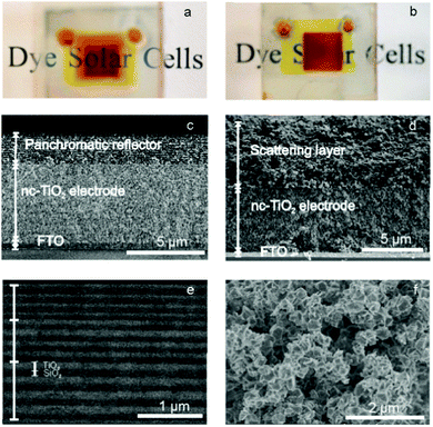
For the purpose of comparison, two sorts of highly reflecting photonic structures and a diffuse scattering layer are built onto the TiO2 electrodes. Among the former, one of them is a nanoparticle based one dimensional photonic crystal (1DPC) fabricated by stacking a total of eight porosity enhanced SiO2–TiO2 nanoparticle bilayers, in which the TiO2 and SiO2 thicknesses (100 and 90 nm, respectively) are kept constant throughout the multilayer. The other is a hierarchical structure constructed from three different 1DPCs deposited one on top of each other. Each one of them has a thickness of 4 unit cells (1 unit cell is equal to 1 TiO2–SiO2 bilayer). In this case, the thickness of the SiO2 layer is fixed for the entire multilayer at 90 nm, while the TiO2 layer thickness decreases along the direction of incident light from 125 nm in the first Bragg stack to 95 nm and 60 nm in the second and third ones. This configuration allows attaining highly reflecting structures covering almost the whole visible range and hence displaying a strong white reflection (please see ESI,† Fig. S2), preserving at the same time the electrode transparency for the longest visible wavelengths, as it can be seen in the pictures displayed in Fig. 1a. It should be remarked that the same dielectric mirrors inversely arranged, so that the lattice constant increases in the direction of incoming light, would result in a lower reflectance structure even with narrow transmission windows located at highly absorbing spectral ranges of the dye. Please see the simulated reflectance, attained using the same code15 employed to design the panchromatic structure, resulting from placing the mirrors in reverse order, as shown in Fig. S3 (ESI†), and the experimental confirmation of such an effect in Fig. S4 (ESI†). For the sake of comparison, a picture of a cell made of a similar nanocrystalline electrode but coupled to a diffuse scattering layer is shown in Fig. 1b. Please note that the underlying text can only be seen through the cell coupled to the photonic multilayer.Field emission scanning electron microscopy (FESEM) images corresponding to cross-sections of a TiO2 nanocrystalline electrode coupled to a white-light reflecting photonic crystal and a diffuse scattering layer made from a standard commercial paste are displayed in Fig. 1c and d, respectively. Please note that the total thickness of the heterogeneous photonic crystal structure proposed herein is around 2 μm, which is significantly thinner than that of the typical diffuse scattering layer (around 5 μm). Analysis of backscattered electron images, like that shown in Fig. 1e, reveals the smooth interface between the two types of porous films that form the broad band dielectric mirror, the different thicknesses of the SiO2 (dark) and TiO2 (bright) layers being readily appreciated. The polyhedral morphology of the particles in the diffuse scattering layer is displayed in Fig. 1f.
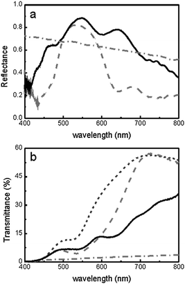
Total reflectance spectra recorded for both the multilayered structures and the diffuse scattering layer after being coupled to the TiO2 electrode are plotted in Fig. 2a. In all cases, samples are infiltrated with ethanol (n = 1.37) to approximate the actual DSC operation conditions, in which the liquid electrolyte fills the pores of the whole ensemble. The latter effect gives rise to lower reflected intensities as the dielectric contrast is decreased and, in the case of the multi-layered stacks, to a red-shift of the reflectance peak position. Such peak displacement was taken into account when designing both the single and triple period photonic lattices to be integrated into the cells. Since photons are reflected by the diffuse scattering layer with a broad angular distribution, spectra were collected in all cases using an integrating sphere. In the case of the photonic crystal structures, the measured total reflectance shows minimum deviations with respect to the specular one, which evidences their low density of imperfections. The single periodicity structure (dashed line) presents a well-defined Bragg peak in the green region of the spectrum (λmax = 530 nm), whereas the second one yields a broader reflectance bandwidth (solid line) like the one displayed by the standard TiO2 scattering layer (dashed–dotted line). In Fig. 2b, ballistic transmittance spectra obtained for the 1DPC based solar cells are plotted (dashed and solid lines for single and triple period structures, respectively), together with the spectra obtained for a reference cell with the same electrode thickness both bare (short dashed line) and coupled to the diffuse scattering layer (dashed–dotted line). It should be remarked that, while the multilayer based cells present an optical transmittance window at the longest visible wavelengths, the diffuse scattering layer turns the cell opaque due to the lack of spectral selectivity of random light scattering. Device transparency data (ISO 9050:2003 standard) are collated in Table 1. It can be observed that the semitransparency of DSCs decreases from around 25% down to 1% when diffuse scattering layers are employed. However, after coupling single and triple period multilayers, transparency values close to 10% are obtained. In the case of the samples chosen as an example, the transparency of the triple period multilayer is even higher than that of the single period 1DPC, which is a consequence of the high sensitivity of this parameter to small changes around wavelengths for which the photopic response of the eye peaks, as explained in the ESI† (please see Fig. S5).
| Optical back scattering material | Transparency (%) | J sc (mA cm−2) | V oc (mV) | FF (%) | η (%) |
|---|---|---|---|---|---|
| None (reference cell) | 24 | 7.33 ± 0.3 | 786 ± 8 | 60.3 ± 3.2 | 3.5 ± 0.2 |
| Single periodicity multilayer | 8.7 | 10.34 ± 0.3 | 780 ± 16 | 55.3 ± 1.8 | 4.5 ± 0.2 |
| Triple periodicity multilayer | 9.5 | 11.35 ± 0.4 | 765 ± 14 | 56.1 ± 3.4 | 4.9 ± 0.4 |
| Diffuser | 1 | 12.35 ± 0.8 | 780 ± 20 | 54.1 ± 2.7 | 5.2 ± 0.4 |
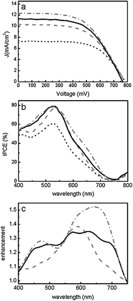
Photocurrent–voltage (IV) curves were obtained for the whole set of samples under standard AM1.5 illumination conditions of 100 mW cm−2 and are shown in Fig. 3a. The main device parameters are presented in Table 1. Comparatively, the multilayer based DSCs show better photovoltaic performance than the reference and, among them, the panchromatic dielectric mirrors give rise to higher short circuit photocurrent density (Jsc), as expected from its broader reflection band. By comparing the power conversion efficiency, η, calculated for these cells, one can see that the efficiency obtained from the white light reflecting PC based cell (4.9%) is very similar to the value attained for the scattering-based cell (5.2%). In the former case, this implies an enhancement in the efficiency of 40% with respect to the reference cell, which is the highest enhancement achieved by coupling a non-disordered porous back reflector to a standard thickness electrode. The fact that reflections arising from a random packing of large particles are oblique gives rise to an extra enlargement of the optical path and thus of the probability of absorption with respect to those achieved using a specular reflector, which explains the stronger reinforcement of efficiency observed for the diffuser. Also, spectral features of the cell performance were analysed by measuring the incident photon to current efficiency (IPCE) in all cases. Results are displayed in Fig. 3b. The corresponding IPCE enhancement factors, γ, calculated as the ratio between the IPCE of the cells under study and that of the reference cell, are plotted in Fig. 3c. The spectral region at which photocurrent generation is improved coincides, as expected, with those at which reflectance is maximum for each type of mirror integrated into the cell. As can be seen, both the white light reflecting multilayer based cell and the diffuse scattering based cell present similar profiles, covering the entire visible region, which is consistent with the observation of comparable conversion efficiencies of both devices.
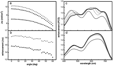
In multilayers, light reflection results from interferometric effects and therefore its intensity and spectral features are dependent on the direction of propagation of light. It has been proved that the angular response of the photocurrent measured for 1DPC based DSCs shows deviations with respect to that of a standard semitransparent cell,16 which follows approximately Lambert's cosine law resulting from the decrease of the effective cross section or apparent surface of the device as it is inclined with respect to a collimated beam. In order to analyse these effects, both IV and IPCE curves were collected at different illumination angles for all cells. In Fig. 4a we plot the angular variation of Jsc measured at 1 sun for the white reflecting multilayer and the diffuse scattering based cells. Results for the semitransparent standard reference cell are also included for the sake of comparison. All tilted cells present performance losses that follow, with minimum deviations, the expected cosine law (please see Fig. S6 and S7, ESI,† for a more detailed analysis). The corresponding evolution of the photocurrent enhancement factors is shown in Fig. 4b. This graph shows that, for a wide range of tilt angles, integration of a panchromatic dielectric mirror provides an improvement in light harvesting almost as independent of the illumination direction as that achieved using the diffuse scattering layer. This effect is observed for light beams impinging between the normal to the cell and approximately 45°. Above this incidence angle, the blue-shift of the photonic crystal reflectance gives rise to lower enhancements at red light frequencies, as it is observed in the IPCE enhancement spectra of the triple period multilayer based cell shown in Fig. 4c. This effect is not compensated by the better performance detected in the blue region and gives rise to a decrease of the overall enhancement with respect to that of the diffuse scattering layer. A similar analysis performed for the diffuse scattering based cell shows that, although the magnitude of the enhancement is also reduced, its relative spectral distribution remains unaltered as the cell is tilted, as can be seen in Fig. 4d.
Conclusion
The results presented herein demonstrate that by integrating a white light reflecting photonic crystal into a dye solar cell it is possible to achieve efficiency values similar to those attained using diffuse scattering-based cells, without the adverse effect the latter ones have on the cell transparency. This is achieved by depositing a nanoparticle based optical multilayer heterostructure with multiple periodicities on top of the nanocrystalline titania electrode. This advance was possible due to the strict control over the overall porosity and pore size distribution of constituent layers of the photonic crystals. Integration of panchromatic specular reflectors of optimized diffusion in DSCs means a step forward towards highly efficient photovoltaic window modules for building integrated photovoltaics based on this third generation technology. Panchromatic mirrors could be designed to match the absorption of any dye attached to the mesoporous titania electrode, so that they can be adapted easily to enhance the performance of a cell that provides the desired color in transmission. This type of mirror could also be used in tandem cells, in which only well-defined ranges of light should be back reflected at different depths of the module.Acknowledgements
The research leading to these results has received funding from the European Research Council under the European Union's Seventh Framework Programme (FP7/2007-2013)/ERC grant agreement no. 307081 (POLIGHT), the Spanish Ministry of Economy and Competitiveness under grants MAT2011-23593 and CONSOLIDER HOPE CSD2007-00007, and the Junta de Andalucía under grants FQM3579 and FQM5247.Notes and references
- S. Ito, S. M. Zakeeruddin, R. Humphry-Baker, P. Liska, R. Charvet, P. Comte, M. K. Nazeeruddin, P. Péchy, M. Takata, H. Miura, S. Uchida and M. Grätzel, Adv. Mater., 2006, 18, 1202 CrossRef CAS.
- Y. Chiba, A. Islam, Y. Watanabe, R. Komiya, N. Koide and L. Han, Jpn. J. Appl. Phys., 2006, 45, 25 CrossRef.
- C. Chen, M. Wang, J. Li, N. Pootrakulchote, L. Alibabaei, C. Ngoc-le, J. D. Decoppet, J. Tsai, C. Grätzel, C. Wu, S. M. Zakeeruddin and M. Grätzel, ACS Nano, 2009, 3, 3103 CrossRef CAS PubMed.
- Y. Cao, Y. Bai, Q. Yu, Y. Cheng, S. Liu, D. Shi, F. Gao and P. Wang, J. Phys. Chem. C, 2009, 113, 6290 CAS.
- A. Yella, H. W. Lee, H. N. Tsao, C. Yi, A. K. Chandiran, M. K. Nazeeruddin, E. W. G. Diau, C. Y. Yeh, S. M. Zakeeruddin and M. Grätzel, Science, 2011, 334, 629 CrossRef CAS PubMed.
- S. Nishimura, N. Abrams, B. A. Lewis, L. I. Halaoui, T. E. Mallouk, K. D. Benkstein, J. van de Lagemaat and A. J. Frank, J. Am. Chem. Soc., 2003, 125, 6306 CrossRef CAS PubMed.
- S. Colodrero, A. Mihi, L. Häggman, M. Ocaña, G. Boschloo, A. Hagfeldt and H. Míguez, Adv. Mater., 2009, 21, 764 CrossRef CAS.
- S. Guldin, S. Huttner, M. Kolle, M. E. Welland, P. Müller-Buschbaum, R. H. Friend, N. Steiner and N. Tetreault, Nano Lett., 2010, 10, 2303 CrossRef CAS PubMed.
- C. T. Yip, H. Huang, L. Zhou, K. Xie, Y. Wang, T. Fenq, J. Li and W. Y. Tam, Adv. Mater., 2011, 23, 5624 CrossRef CAS PubMed.
- D. Colonna, S. Colodrero, H. Lindström, A. Di Carlo and H. Míguez, Energy Environ. Sci., 2012, 5, 8238 CAS.
- M. Guo, K. Y. Xie, J. Lin, Z. H. Yong, C. T. Yip, L. M. Zhuo, Y. Wang and H. T. Huang, Energy Environ. Sci., 2012, 5, 9881 CAS.
- S. Colodrero, A. Forneli, C. López-López, L. Pellejà, H. Míguez and E. Palomares, Adv. Funct. Mater., 2012, 22, 1303 CrossRef CAS.
- C. López-López, S. Colodrero, S. R. Raga, H. Lindström, F. Fabregat-Santiago, J. Bisquert and H. Míguez, J. Mater. Chem., 2012, 22, 1751 RSC.
- S. D. Burnside, V. Shklover, C. Barbe, P. Comte, F. Arendse, K. Brooks and M. Grätzel, Chem. Mater., 1998, 10, 2419 CrossRef CAS.
- G. Lozano, S. Colodrero, O. Caulier, M. E. Calvo and H. Míguez, J. Phys. Chem. C, 2010, 114, 3681 CAS.
- C. López-López, S. Colodrero, M. E. Calvo and H. Míguez, Energy Environ. Sci., 2013, 6, 1260 Search PubMed.
Footnote |
| † Electronic supplementary information (ESI) available. See DOI: 10.1039/c3cp53939c |
| This journal is © the Owner Societies 2014 |


