 Open Access Article
How to print a crystal structure model in 3D†
Teng-Hao
Chen
*a,
Semin
Lee
b,
Amar H.
Flood
b and
Ognjen Š.
Miljanić
a
aDepartment of Chemistry, University of Houston, 112 Fleming Building, Houston, Texas 77204-5003, USA. E-mail: tchen21@uh.edu; Fax: +1 713 743 2709; Tel: +1 832 842 8827
bDepartment of Chemistry, Indiana University, 800 E. Kirkwood Avenue, Bloomington, Indiana 47405, USA. Tel: +1 812 856 3642
First published on 4th April 2014
Abstract
We present a simple procedure for the conversion of Crystallographic Information Files (CIFs) into Virtual Reality Modelling Language (VRML2, .wrl) files, which can be used as input files for three-dimensional (3D) printing. This procedure permits facile production of customized full-colour 3D models of X-ray crystal structures of segments of extended structures, including metal–organic frameworks (MOFs) as well as small molecules. The method uses freely available software that runs under Microsoft Windows, MacOSX and Linux operating systems.
Introduction
Three-dimensional (3D) printing or additive manufacturing is a process of making a three-dimensional solid object of virtually any shape from a digital model. This powerful technology is no longer futuristic, as the cost of 3D printing has dropped dramatically over that past decade, making it affordable even to a hobbyist. 3D printing has been touted as ushering “the third industrial revolution”—that of mass customization, wherein virtually any consumer object could be tailored to a previously unprecedented level.1 This technology will likely revolutionize numerous fields of human activity; as just one example, prosthetic medicine could soon count on implants perfectly matching each individual patient. 3D printing is beginning to affect chemical research as well: Cronin et al. have recently reported the creation of customized 3D-printed “reactionware”, the composition and shape of which allow its active participation in the reaction and analysis of products.2Chemistry is full of concepts that require three-dimensional understanding, and representing those in two-dimensional PowerPoint slides, journal articles, or on chalkboards inevitably leads to a loss of detail. Crystallography is even more dependent on 3D representations, and most readers of this journal have likely spent numerous hours turning crystal structure models on their computer screens to produce a view that sacrifices the least information. An ability to easily build 3D models of crystal structures is thus clearly needed. In this contribution, we provide step-by-step instructions on how to convert a .cif file—which is a typical end product of crystal structure refinement—into a 3D-printed physical model of a crystal structure. We use MOFF-3 (Fig. 1)—one of our previously published extended metal–organic framework (MOF) structures3—as an illustration for this method. This procedure is broadly applicable to many other structures; in our two labs, we have printed 3D models of more than thirty different small molecules and MOFs.
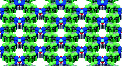 | ||
| Fig. 1 The starting point: 2D representation of the MOFF-3 structure produced directly from its .cif file using Mercury 3.3. | ||
Our procedure is neither the only nor the first method for achieving the conversion of crystallographic information files into 3D printed models.4 Its advantages are: (a) the ability to produce models of both discrete molecules and segments of extended “infinite” structures such as MOFs; (b) the use of freely available and highly intuitive software packages (vide infra) with ample helpful documentation available online; and (c) its reliance on a commercial 3D printing service provided by Shapeways, which obviates the need for an in-house 3D printer.
The main disconnect between the crystal structure manipulation programs and the 3D printing software lies in the mutual incompatibility of file formats. Out of the commonly used crystal structure processing programs, only PyMOL5 is able to directly export crystal structure data contained in .cif files into the VRML (.wrl) format most commonly used for colour 3D printing.6 This feature enables the printing of small molecule models via PyMOL (see the ESI† for photos and movies of 3D models of selected small molecules: triazolophanes,7 cyanostars8 and cyanostar-[3]rotaxane). However, many crystal structure processing operations—e.g. connectivity expansion, addition of multiple unit cells, etc.—are rather difficult to do in PyMOL. Our protocol thus resorts to using two programs which together offer greater flexibility in manipulating both the crystal structure and the 3D model. Mercury9 is used to produce a .pdb file of the crystal structure, which is then imported into Blender10—a semi-professional 3D printing program—for additional processing and conversion into a .wrl file. This combination is necessary since Blender appears to be unable to import .pdb files produced by programs other than Mercury.
Procedure
Four separate pieces of software are required for this conversion: Mercury 3.3,9 Blender 2.62 and 2.69,10 and the open-source embedded Python Molecular Viewer (ePMV) plugin, which runs molecular-modelling software directly in Blender.11 In our work, we used the Windows versions of these programs as well as MacOSX (Mercury 3.1.1 and Blender 2.62 and 2.70); since all of the requisite programs are also available for the Linux operating system, it is reasonable to assume that a very analogous procedure should function on this platform as well.Instructions are as follows:
1. Set user preferences in Blender 2.62. Open Blender 2.62 then click on File > User Preferences > Addons. Make sure that under the Import–export tab, option Web3D X3D/VRML format is checked. Under the System tab, options autoPack, ePMV and ePMV synchro should all be checked. Click on Save as Default. As a result, ePMV and autoPACK buttons will show in the upper right corner of the Blender 2.62 window.
2. Set user preferences in Blender 2.69. Open Blender 2.69 then click on File > User Preferences > Addons. Make sure that under the Import–export tab, options Web3D X3D/VRML format and VRML2 (Virtual Reality Modelling Language) are both checked. Under the Mesh tab, option 3D Print Toolbox should be checked. Click on Save User Settings.
3. Open the crystal structure's CIF file in Mercury and produce the desired packing (one or more molecules/unit cells). At this stage, it may be also useful if disordered atoms or side chains are deleted so that only one orientation remains—unless the objective is to highlight the disorder. To delete undesired features of the structure, click on Edit > Edit Structure… > Remove, and then click on the atoms or molecules that need to be removed.
4. The resulting data should be saved as a PDB file (File > Save As…). In our case, only PDB files produced by Mercury could be successfully used in the subsequent steps.
5. Open Blender 2.62 and click on the ePMV button on the top right. As a result, the ePMV interface will appear on the left-side panel. Delete the cube, camera, and light objects in the main Blender window (this is done by simply right-clicking on those objects followed by pressing the Delete button).
6. In the ePMV panel, choose Browse and navigate to the PDB file produced in step 4. Upon loading, a series of dots will appear in the main Blender window; these represent individual atoms.
7. In the Atom/Bond Representation subpanel on the left, choose the desired structural representation; for most organic and inorganic structures, Atoms or Sticks representations are the most appropriate. The ensuing calculation will take between several seconds and several hours depending on the complexity of the structure. Values for the cpk_scale, bs_scale, and bs_ratio, as well as element colours should be adjusted at this point (if desired), since further changes are not permitted after the file is saved. Changing these parameters will affect all atoms (or bonds) of a given kind; individual atoms can also be modified using the description given in step 10 below.
8. Save the file and export it as an .x3d file: click on File > Export > X3D Extensible 3D (.x3d).
9. Close Blender 2.62 and open Blender 2.69. Import the .x3d file created in the previous step: click on File > Import > X3D Extensible 3D (.x3d).
10. In Object Mode, you can select and delete individual atoms and bonds and adjust the size of any item (Fig. 2, top). For example, to adjust the size of an atom, right-click on the desired atom and choose Scale in the Object Tools on the interface on the right. To change the color of atoms and bonds, click on the Material icon  . Click (−) to remove the original material and (+) to add a new one. The color can be adjusted using the Diffuse option. You can rename the material and click
  to save it then apply it to any item that you want to have the same color. This feature is particularly useful if certain parts of the structure need to be emphasized.
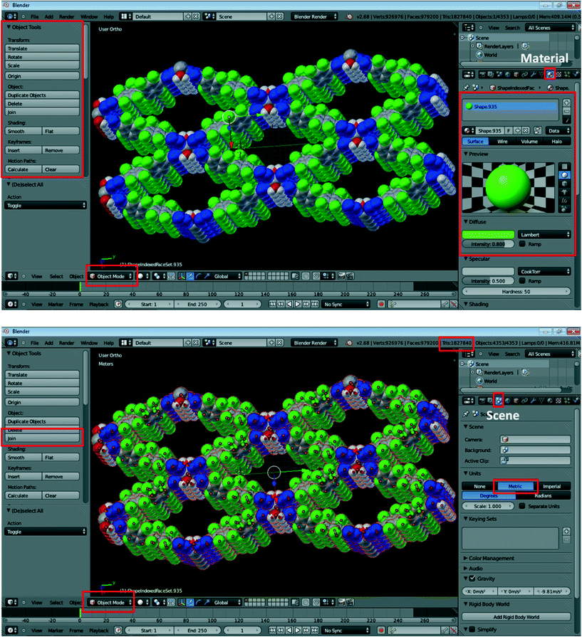 | ||
| Fig. 2 Exemplary screenshots during the processing of crystal structure data using Blender. Specific buttons required in this procedure are highlighted in red; refer to the text for details. | ||
11. The produced model will most likely need to be resized to be of dimensions that are practical for printing. To do so, click on the Scene button on the right-side panel (third button from the left; highlighted in red in Fig. 2, bottom). Change Units to Metric. Then, select all atoms by pressing A (with the cursor located in the view window), which should result in the entire structure being highlighted in the main Blender window. Click on Join on the left-side panel to connect all of the separate parts, and then use the Scale button in the left-side panel to adjust the size of the structure. We have typically found the originally imported structures to be too large, and most of them needed to be scaled down. It should be noted that the dimensions provided by Blender do not correlate well with the size of the printed model (vide infra), so adjustment of dimensions for 3D printing requires some trial and error.
12. Once satisfied with the model size, click on the Object Mode button on the bottom left and switch the selection to Edit Mode. Then, press W (with the cursor located in the view window) and click on Remove Doubles, which should remove artefact vertices in the structure.
13. Export the resultant data to a VRML2 (.wrl) file: click on File > Export > VRML2 (.wrl).
14. The created .wrl file can now be handled by many commercial and academic 3D-printing facilities. Models presented in this work have been printed by the popular website Shapeways.12 After brief user registration, the source file can be uploaded onto the Shapeways website by clicking on Make + Sell > Upload > Select 3D File and then choosing the produced .wrl file. Units should be set to inches, and the Upload Now button should be clicked. The Shapeways website will then perform the upload, estimate the model size, and confirm whether the model is indeed printable. The two most commonly encountered problems during the upload are the large file sizes (Shapeways imposes a limit of 64 megabytes, which can be somewhat expanded by uploading compressed ZIP files) and a large number of polygons. The latter are created during conversion of the structure in Blender and their number can be checked by consulting the Tris number on the top-right bar in the Blender window (Fig. 2, bottom). Shapeways limits the complexity of the uploaded models to 1![[thin space (1/6-em)]](https://www.rsc.org/images/entities/char_2009.gif) 000
000![[thin space (1/6-em)]](https://www.rsc.org/images/entities/char_2009.gif) 000 polygons.
000 polygons.
15. If the model size is not satisfactory, the model should be scaled again (steps 11 and onward) and the process repeated until a desired size is obtained as the estimate. Once the model size is finalized, the Shapeways team will check the printability of the proposed model and inform the user if there are potential issues. If no error is reported, the model can be printed. All that remains is to choose a material for the 3D model. At the time of this writing, Shapeways offered a wide variety of plastic, ceramic and metallic substrates (steel, silver, brass, bronze), but the only material offering full-colour functionality was Full Color Sandstone, a proprietary mixture of plasters, vinyl polymers, and carbohydates.13 Incidentally, this is one of the least expensive 3D printing materials offered. If a monochromatic model is desired, we anticipate that most other materials would function well (although we have not tested them).
16. If printability errors are reported, they are most commonly related to the physical limitations of the sandstone material used in printing. Thus, structures with many bonds may make those bonds too thin (<2 mm) to support themselves; in such cases, either a smaller fragment of the structure should be chosen for printing or the representation should be switched to Space-filling, with larger cpk_scale values used in step 7.
An example of a finished model is shown in Fig. 3. At current (February 2014) prices, a model similar to the one shown in Fig. 3 will cost between $20 and $100 depending on the size.14 Because sandstone is essentially plaster, models produced from it are rather fragile (they will easily shatter if dropped), thermostable only up to 60 °C, not resistant to water and have grainy surfaces. There are two solutions to the last two problems. First, the printed model can be dipped in glue (e.g. ZPrinter Z-Bond 90 Infiltrant) to form a coating that gives a strengthened material with a glossy finish when dried. The usage and safety instructions for this product should be followed. For example, when the models are dipped into a plastic container full of the glue, there is a large temperature increase (exothermic) and outgassing is significant enough to warrant the use of personal protective equipment and a ventilated area (fume hood). The model is then patted dry to remove excess glue. The glue penetrates ~2 mm into the model; excess glue will pool and deteriorate the finish. A simpler method that gives similar results makes use of a glossy acrylic spray that can be applied with repetitive spray–dry cycles (4–5 times).
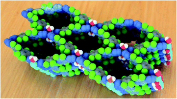 | ||
| Fig. 3 The finished product: 3D printed model of the MOFF-3 structure. Approximate dimensions: 16 × 8 × 7 cm. | ||
Conclusions
In conclusion, we presented here a set of guidelines on how to convert any small-molecule or extended material crystal structure into a 3D printed model. The value of these models should be in facilitating communication of crystal structure details both in the classroom and between experienced practitioners in the field. Our set of instructions uses freely available software, requires no programming knowledge and no knowledge of 3D printing techniques, and produces models using a commercial easy-to-use website.As with many rapidly developing technologies, we expect these instructions to be outdated within several years, as 3D printers enter the mainstream and crystal structure processing software becomes better integrated with this obviously very relevant technology. Until then, we hope that our colleagues will find this protocol—and its 3D-printed products—useful and educational.
Note added in proof
During the production of this paper, two related papers also in production came to our attention: (a) P. Kitson, A. Macdonell, S. Tsuda, H. Zang, D.-L. Long and L. Cronin, Cryst. Growth Des., 2014, 10.1021/cg5003012. (b) V. F. Scalfani and T. P. Vaid, J. Chem. Educ., 2014, 10.1021/ed400887t.Acknowledgements
This work was supported by the National Science Foundation CAREER program (awards CHE-1151292 to O. Š. M., CHE-0844441 to A. H. F.), the Welch Foundation (award E-1768 to O. Š. M.) and the donors of the American Chemical Society Petroleum Research Fund (award DNI-50390 to O. Š. M.). O. Š. M. is a Cottrell Scholar of the Research Corporation for Science Advancement. A. H. F. is a Camille Dreyfus Teacher-Scholar and S. L. is a Chester Davis Fellow. S. L. and A. H. F. thank Nicole Jacquard, the Department of Fine Arts, and the Advanced Visualization Lab at Indiana University for printing.Notes and references
- Additive Manufacturing: Solid Print, in The Economist Special Report on Manufacturing and Innovation, April 21 2012, pp. 14–15 Search PubMed.
- (a) J. S. Mathieson, M. H. Rosnes, V. Sans, P. J. Kitson and L. Cronin, Beilstein J. Nanotechnol., 2013, 4, 285–291 CrossRef CAS PubMed; (b) P. J. Kitson, M. D. Symes, V. Dragone and L. Cronin, Chem. Sci., 2013, 4, 3099–3103 RSC; (c) P. Kitson, M. Rosnes, V. Sans, V. Dragone and L. Cronin, Lab Chip, 2012, 12, 3267–3271 RSC; (d) M. D. Symes, P. J. Kitson, J. Yan, C. J. Richmond, G. J. T. Cooper, R. W. Bowman, T. Vilbrandt and L. Cronin, Nat. Chem., 2012, 4, 349–354 CrossRef CAS PubMed.
- T.-H. Chen, I. Popov, O. Zenasni, O. Daugulis and O. Š. Miljanić, Chem. Commun., 2013, 49, 6846–6848 RSC.
- For examples of printing structures of distinct proteins, see: http://cbe.wisc.edu/assets/docs/pdf/srp-bio/stongrevised.pdf. For small molecules and proteins, see: http://barneybioproductslab.cfans.umn.edu/3d-printing-and-molecular-models/. For a commercial service offering 3D printed molecular models, see: http://models.scripps.edu/. See also: N. Jones, Nature, 2012, 487, 22–23 CrossRef CAS PubMed.
- The PyMOL Molecular Graphics System, Version 1.5.0.4, Schrödinger, LLC. Freely available from: www.pymol.org Search PubMed.
- It should be noted that other 3D printing file formats (e.g. .STL) can be used if colour models are not required. There is much instructional value in monochromatic models as well, since they can be printed quickly and inexpensively on many of the hobbyist 3D printers that use ABS plastics as substrates. Full colour 3D printers are still prohibitively expensive (and large) for individual use, and are thus typically housed in commercial and academic facilities..
- Y. Li and A. H. Flood, Angew. Chem., Int. Ed., 2008, 47, 2649–2652 CrossRef CAS PubMed.
- S. Lee, C.-H. Chen and A. H. Flood, Nat. Chem., 2013, 5, 704–710 CrossRef CAS PubMed.
- Freely available for Linux, MacOSX and Windows operating systems, from: http://www.ccdc.cam.ac.uk/Solutions/CSDSystem/Pages/Mercury.aspx. Last accessed on February 11, 2014.
- Blender is free software, available for Linux, MacOSX and Windows operating systems at: http://www.blender.org/download/. Last accessed on February 11, 2014. Blender is convenient to use because of the wealth of user documentation freely available online, which is further complemented by numerous YouTube videos illustrating individual features. This body of helpful information should make troubleshooting easier for the users of our procedure.
- Freely available at: http://epmv.scripps.edu/download-install-free/installers/. ePMV is available for Linux, MacOSX and Windows operating systems. Last accessed on February 11, 2014. Note that—at the time of this writing—ePMV operates on Blender 2.62, which is not the same as the latest version of the program (Blender 2.69 for Windows and Blender 2.70 for MacOSX). Therefore, both versions of Blender should be downloaded and used, which is fortunately possible. It is reasonable to assume that these functionalities will eventually be combined in a single version of the program, which would simplify our procedure. See also: G. T. Johnson, L. Autin, D. S. Goodsell, M. F. Sanner and A. J. Olson, Structure, 2011, 19, 293–303 CrossRef CAS PubMed.
- http://www.shapeways.com .
- Material Safety Data Sheet (MSDS) for Full Color Sandstone can be found at: http://www.shapeways.com/rrstatic/material_docs/m-sds-sandstone.pdf.
- For comparison, building a model of MOFF-3 similar to the one shown in Fig. 3, but using modular commercial molecular model kits would cost approx. $300. In addition, these sizes of atoms in these kits are too large to make them practical for MOF structures with numerous atoms; thus, a single unit cell model for MOFF-3 would be 30 × 30 × 30 cm large. 3D Printed models permit much smaller feature sizes.
Footnote |
| † Electronic supplementary information (ESI) available: (a) Source files (.cif, .pdb, .x3d, .wrl) for all stages of production of the MOFF-3 3D structure model; (b) an addendum on 3D printing of dynamic models of supramolecular complexes and mechanically interlocked molecules; and (c) movies of those complexes/molecules in motion. See DOI: 10.1039/c4ce00371c |
| This journal is © The Royal Society of Chemistry 2014 |

