Simple fabrication and electrochemical performance of porous and double-shelled macroporous CuO nanomaterials with a thin carbon layer†
HyunMee Kim‡
a,
Hyung-Seok Lim‡a,
Yu-Jeong Kima,
Yang-Kook Sunb and
Kyung-Do Suh*a
aDivision of Chemical Engineering, College of Engineering, Hanyang University, Seoul 133-791, Republic of Korea. E-mail: kdsuh@hanyang.ac.kr; Fax: +82-2-2220-4680; Tel: +82-2-2220-0526
bDivision of WCU Engineering, College of Engineering, Hanyang University, Seoul 133-791, Republic of Korea. E-mail: yksun@hanyang.ac.kr; Tel: +82-2-2220-1749
First published on 29th October 2014
Abstract
In this work, different types of CuO particles with a thin carbon layer were fabricated and tested as anode materials for lithium ion batteries. The pH-responsive hydrogel microspheres are utilized as a template for morphological and structural changes of composite particles. The structure of CuO particles and a thin carbon layer have the effect to improve the electrochemical performances of the lithium ion cells.
Introduction
In recent years, lithium ion batteries (LIBs) have been commonly used as energy storage devices in digital cameras, smart phones, laptop/tablet computers, wireless home appliances, and other electric devices. However, in order to develop next-generation LIBs for more sustainable mobile devices, electric vehicles, and energy storage systems, electrode materials with higher capacity and superior stability must be developed. Transition metal oxides (TMOs: M = Fe, Cu, Co, Ni, and Zn) have garnered interest as alternative anode materials for next-generation LIBs instead of graphite, because conversion reaction-based anodes show much higher theoretical capacity than graphite anodes.1 However, these materials cannot be deployed on a commercial scale because of their poor capacity retention during continuous cycling. Since TMOs have intrinsically low electrical conductivity, and their volume variation during lithiation–delithiation causes poor cell cyclability,2 nanostructured3 and carbon composite TMO-based4 anodes have been investigated by many research groups in an attempt to improve conductivity. Nanostructured materials, such as nanoparticles,5 nanorods,6 and nanofibers,7 exhibit improved cyclability, efficiency, and better rate capabilities, even at high current rates, due to the short diffusion lengths of their electroactive components and their large active sites.8 However, despite these attractive advantages of TMO nanomaterials, some disadvantages remain to be addressed. These include poor capacity retention caused by low electrical conductivity, enormous volume variation, and severe aggregation caused by high surface free energy.9 The application of a carbon coating is one method to overcome the poor capacity retention of these materials. Since carbon can deter intense structural conversion and improve the electrical conductivity of active materials, various carbon composite anode materials have recently been reported.10 Carbon composite anode materials have been synthesized through various synthetic methods such as chemical vapor deposition (CVD), pyrolysis, and hydro/solvothermal synthesis.11 Another effective way to improve the electrochemical properties is by introducing void space, such as meso and macro pores, to serve as a buffering space that accommodates the volume expansion.10,12 Our research group previously confirmed that the introduction of void space can improve cyclability, as experimentally demonstrated by comparing the capacity retention of hollow, structured Fe3O4 submicron spheres and Fe3O4 nanoparticles.12 Furthermore, we reported that the spherical hydrogel template used to prepare rattle structured α-Fe2O3 submicron spheres can contribute to formation of a thin carbon layer on the surfaces of α-Fe2O3 nanograins. This thin carbon coating is formed during the decomposition of the polymer chains when they are heated in a certain gaseous atmosphere.13 The rattle-type structure of α-Fe2O3 submicron spheres is formed by Ostwald ripening, which contributes to the good capacity retention at high current rates; the internal void space and thin carbon layer reduce the charge-transfer resistance of the cells.Herein, we report the simple fabrication of porous CuO spheres and three-dimensionally ordered macroporous CuO with a double shell and a thin carbon layer (porous CuO/C and 3DOM-CuO/C), without the need for an extra carbon-coating process. Some papers related to the high-performance CuO anodes with carbon and conducting polymer have been reported.14 In our study, however, the experimental system to coat the carbon layer and to control the structures is quite unlike above researches. The three-dimensional structure of CuO is generated by a simple synthetic method that uses spherical hydrogel particles as a template to accommodate large volume variation and desirable Li ion kinetics. In addition, the thin carbon layer formed on the inner/outer shell surfaces not only alleviates the mechanical stress of macroporous CuO during continuous cycling, but also reduces the charge-transfer resistance of the cells. The internal structure and the surface area of 3DOM-CuO/C can be adjusted by changing the pH during the synthetic process. After fabrication of porous CuO/C and the double-shelled 3DOM-CuO/C, thin carbon layers coated on the surfaces of the inner portions of the particles were characterized by HR-TEM and EDX line profiles. Additionally, 3DOM-CuO/C was tested as an anode material for lithium ion batteries and characterized electrochemically to determine the effects of the ordered 3D structure and the thin carbon layer on device performance.
Experimental
Materials
Copper(II) sulfate pentahydrate (CuSO4·5H2O, Yakuri Pure Chemical Co., Ltd.), methacrylic acid (MAA, Junsei Chemical), ethylene glycol dimethacrylate (EGDMA, Tokyo Kasei Kogyo), α,α'-azobis-(isobutyronitrile) (AIBN, Junsei Chemical), acetonitrile (DeaJung Chemicals & Metals Co., Ltd.), sodium hydroxide (NaOH, Sigma Aldrich), an ammonium hydroxide solution (DeaJung Chemicals & Metals Co., Ltd.), anhydrous ethyl alcohol (ethanol, DeaJung Chemicals & Metals Co., Ltd.), and distilled water (DI water) were purchased and used as received.Preparation of poly(MAA/EGDMA) microspheres
Poly(MAA/EGDMA) microspheres were synthesized by distillation–precipitation polymerization:17 DI water (24.0 g) and acetonitrile (136.0 g) were mixed in a round-bottom flask used as a reactor. AIBN, used as an initiator, was dissolved in a monomer mixture consisting of MAA (15.0 g) and EGDMA (5.0 g). The monomer mixture was poured into the reactor and polymerized at 88 °C until a certain amount of the medium was evaporated from the reactant. The precipitates were then obtained by centrifugation. The hydrogel particles were washed several times with ethanol and DI water and dried under vacuum.Preparation of porous CuO/C and double-shelled 3DOM-CuO/C
In a four-neck flask, 0.3 g of poly(MAA/EGDMA) microspheres were dispersed and stirred at a speed of 200 rpm in 300 ml of two alkaline aqueous solutions with different pHs adjusted with 3 M NaOH with nitrogen purging at room temperature for 4 h. Then, 300 ml of a CuSO4 solution (2.6 mM) was poured into the reactor and stirred continuously for 12 h. Next, 27 ml of an NH4OH solution was added into the reactor, and the mixture was centrifuged after 2 h. The obtained products were washed several times with ethanol and freeze-dried. The as-prepared Cu precursors/poly(MAA/EGDMA) microspheres were heated to 500 °C at 5 °C min−1 and maintained for 2 h at 500 °C under a gaseous mixture condition (mainly air) in order to obtain porous CuO spheres (porous CuO/C) and three-dimensionally ordered macroporous CuO with a thin carbon layer (3DOM-CuO/C).Characterization
All products were characterized with X-ray diffraction (XRD), Fourier-transform infrared spectroscopy (FT-IR, Nicolet Magna IR-550), scanning electron microscopy (SEM, JSM-6300, JEOL), focused-ion beam scanning electron microscopy (FIB-SEM, Hitachi S-4800), transmission electron microscopy (TEM, JEOL, JEM-2000EX), high-resolution transmission electron microscopy (HR-TEM, JEM-2100F), optical microscopy (OM, Olympus, BX51), and a zeta-potential analyzer (Zetasizernano ZS, Malvern Instruments).Electrochemical Measurements
Electrochemical characteristics of the porous CuO/C and 3DOM-CuO/C as anode materials were investigated using 2032 coin-type cells. The electrode slurries were fabricated by mixing 3DOM-CuO/C powder (70 wt%), super-P as a conductive agent (15 wt%), and carboxymethyl cellulose (CMC, 7.5 wt%): polyacrylic acid (PAA, 7.5 wt%) as binders. The mixed slurry was plastered onto a Cu foil via doctor blading. The electrode was dried for 20 min in a 110 °C oven and roll-pressed. The coin cells were assembled in an argon-filled glove box. Li metal foil was used as a counter electrode, and ethylene carbonate/diethyl carbonate (EC/DEC, 1![[thin space (1/6-em)]](https://www.rsc.org/images/entities/char_2009.gif) :
:![[thin space (1/6-em)]](https://www.rsc.org/images/entities/char_2009.gif) 1 by volume, provided by Techno Semichem Co. Ltd., Korea) was used as an electrolyte. The cell performance was tested galvanostatically and charged and discharged in the voltage range between 0.02 and 3.0 V at room temperature. Electrochemical impedance spectroscopy (EIS) measurements were performed using a Zahner Elektrik IM6 at frequencies ranging from 5 mHz to 100 kHz with an amplitude of 50 mV.
1 by volume, provided by Techno Semichem Co. Ltd., Korea) was used as an electrolyte. The cell performance was tested galvanostatically and charged and discharged in the voltage range between 0.02 and 3.0 V at room temperature. Electrochemical impedance spectroscopy (EIS) measurements were performed using a Zahner Elektrik IM6 at frequencies ranging from 5 mHz to 100 kHz with an amplitude of 50 mV.
Results and discussion
In this study, porous CuO submicron spheres and three-dimensionally ordered macroporous CuO with a thin carbon layer (porous CuO/C and 3DOM-CuO/C) were synthesized using poly(MAA/EGDMA) microspheres as a sacrificial template and the diffusion of Cu ions. This method does not require extra processing steps for shell formation or carbon-coating. Our strategy is based on the electrostatic interaction between the Cu precursors and the ionized carboxyl groups of the polymer backbone. Since the inner structure of the CuO particles varies depending on the pH of the reaction medium, the poly(MAA/EGDMA) microspheres swelled in alkaline aqueous solutions with different pHs. Ionized Cu ions from copper(II) sulfate pentahydrate can exist as Cu2+ and Cu(OH)2 in an alkaline aqueous solution. For convenience, we refer to these species as “Cu precursors” in this work. After swelling the poly(MAA/EGDMA) microspheres, Cu precursors of two types were allowed to diffuse into the swollen templates based on the presence of a concentration gradient and electrical charge attraction. Then, the obtained Cu precursors/poly(MAA/EGDMA) composite microspheres underwent heat treatment after freeze-drying in order to obtain porous CuO spheres with a thin carbon layer and different macroporous structures. These are formed through polymer decomposition and simultaneous CuO crystal growth, as schematically illustrated in Fig. 1.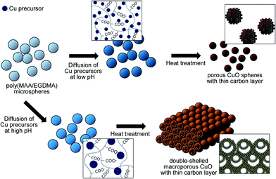 | ||
| Fig. 1 Schematic illustration of the fabrication process for porous submicron spheres and double-shelled three-dimensionally ordered macroporous CuO with a thin carbon layer. | ||
The poly(MAA/EGDMA) microspheres were synthesized by distillation–precipitation polymerization. During fabrication of the poly(MAA/EGDMA) microspheres, the change of medium solvency induced by the evaporation of the solvent resulted in the precipitation of propagating polymer chains caused by hydrophobic interactions. The poly(MAA/EGDMA) microspheres have a narrow size distribution because they were stabilized by the electrostatic repulsion produced by the carboxylic acid groups during polymerization, as shown in Fig. S1b.† Fig. S1a† shows the FT-IR spectrum of poly(MAA/EGDMA) microspheres. One strong peak around 1700 cm−1 is attributed to the stretching vibrations corresponding to OH and C![[double bond, length as m-dash]](https://www.rsc.org/images/entities/char_e001.gif) O of the carboxyl group in the cross-linked polymer chains. The average diameter of poly(MAA/EGDMA) microspheres was 0.92 μm after freeze-drying (SEM image, Fig. S1b†). This value increased to 1.27 μm and 1.45 μm in alkaline aqueous solutions pHs of 6.44 and 9.05, respectively (OM image, Fig. S1c and d†). When dispersed in the reaction medium, carboxyl groups (–COOH) lost their protons and were converted to carboxylate ions (–COO−), causing the repulsion between polymer chains. When a CuSO4 solution was added to the aqueous solution containing the swollen polymer microspheres in each experimental condition, the translucent white stationary reaction system consisting of poly(MAA/EGDMA) microspheres and aqueous solution of each pH immediately turned light blue. After adding an ammonia solution, the color of the stationary reaction system immediately changed to a deep blue.
O of the carboxyl group in the cross-linked polymer chains. The average diameter of poly(MAA/EGDMA) microspheres was 0.92 μm after freeze-drying (SEM image, Fig. S1b†). This value increased to 1.27 μm and 1.45 μm in alkaline aqueous solutions pHs of 6.44 and 9.05, respectively (OM image, Fig. S1c and d†). When dispersed in the reaction medium, carboxyl groups (–COOH) lost their protons and were converted to carboxylate ions (–COO−), causing the repulsion between polymer chains. When a CuSO4 solution was added to the aqueous solution containing the swollen polymer microspheres in each experimental condition, the translucent white stationary reaction system consisting of poly(MAA/EGDMA) microspheres and aqueous solution of each pH immediately turned light blue. After adding an ammonia solution, the color of the stationary reaction system immediately changed to a deep blue.
These color changes resulted from the following chemical reaction:
| Cu2+ + 2OH− → Cu(OH)2 |
| Cu(OH)2 + 4NH3 → [Cu(NH3)4]2+ + 2OH− |
When copper(II) hydroxide reacts with ammonia, it forms a chelate consisting of [Cu(NH3)4]2+ complex ions known as Schweizer's reagent. Accordingly, Cu2+, Cu(OH)2 and [Cu(NH3)4]2+ are formed after addition of ammonium solution. These species can diffuse into the poly(MAA/EGDMA) microspheres by electrical attraction and the presence of a concentration gradient. After stirring for 12 h and washing and drying the particles, variation is produced with regard to the shade of blue. Therefore, we assumed that the Cu precursors in poly(MAA/EGDMA) microspheres were Cu2+ and Cu(OH)2. The SEM images in Fig. 2a and b show that the particle size and morphologies of Cu precursors/poly(MAA/EGDMA) composite microspheres were similar to those of the poly(MAA/EGDMA) composite particles before introduction of the Cu precursors. Fig. 2c shows that the loss amounts of poly(MAA/EGDMA) and two types of Cu precursors/poly(MAA/EGDMA) composite microspheres prepared under different pHs were 3.79%, 17.09%, and 23.61%, respectively. These TGA curves show different residual masses and thermal degradation processes. While the first weight loss of poly(MAA/EGDMA) microspheres occurred at 380 °C, the Cu precursors/poly(MAA/EGDMA) composite microspheres decomposed rapidly before the temperature reached 200 °C, because the decomposition temperature of Cu(OH)2 is 185 °C. Furthermore, during the decomposition process of Cu(OH)2 at high temperatures, Cu2+ ions acted as a catalyst for polymer degradation. Transition metal oxides cause side reactions, generate intermediates, and cause thermal degradation of several polymers by catalyzing polymer chain scission at high temperatures.15 Since Cu2+ ions were present in almost every portion of the poly(MAA/EGDMA) chains, the overall decomposition process curve of Cu precursors/poly(MAA/EGDMA) composite microspheres was different from that of poly(MAA/EGDMA) microspheres. Based on the TGA curves, we concluded that the Cu precursors were successfully diffused into the chain networks of poly(MAA/EGDMA) microspheres.
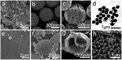
X-ray diffraction (XRD) patterns of the heat-treated samples only show peaks that indicate monoclinic CuO; there were no impurity peaks (Fig. 3). Fig. 4 shows (a, b, e and f) SEM, (e and g) cross-sectional and (d and h) TEM images of porous CuO/C submicron spheres and 3DOM-CuO/C with double shell.
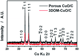 | ||
| Fig. 3 X-ray diffraction patterns of porous CuO/C (black) submicron spheres and double-shelled 3DOM-CuO/C (red) after heat treatment. | ||
Fig. 4 shows the morphologies of each Cu precursors/poly(MAA/EGDMA) composite microsphere after heat treatment for 2 h at 500 °C under a gaseous mixture (mainly air). The morphologies of the obtained porous CuO submicron spheres and 3-DOM CuO were investigated by SEM, FIB-SEM, and TEM. Porous spheres were obtained under the lower pH condition and had a narrow size distribution, as shown in Fig. 4a–d. The average diameter of the porous CuO submicron spheres was 488 nm. We obtained 3DOM-structured CuO under the higher pH condition, and the submicron spheres of the bulk particles had a double-shell structure (Fig. 4e–h). The cross-sectional image shows that the average diameters of the outer- and inner-shells were 449 nm and 213 nm, respectively.
In a previous study, we fabricated hollow and rattle-type spherical α-Fe2O3 particles with a thin carbon layer using poly(MAA/EGDMA) microspheres under different pHs. The formation of thin carbon layers on the inner and outer surfaces were investigated and were demonstrated to enhance the electrochemical performance of the obtained rattle-type α-Fe2O3 submicron spheres as anode materials for LIBs. In this work, in order to identify the formation of a thin carbon layer on the surface of porous and 3DOM-structured CuO with double shells, high-resolution transmission electron microscopy (HR-TEM), energy-dispersive X-ray spectroscopy (EDX) line profiles, and X-ray photoelectron microscopy (XPS) were used, as shown in Fig. 5 and S3.† The chemical components of the amorphous thin layer were clearly verified by EDX line profiling (Fig. 5a and b) using STEM images. The EDX spectra show the detection locations of Cu (blue line), O (red line), and C (green line). These spectra show that carbon existed discontinuously on the pores and in the inner and outer shells of porous CuO/C and double-shelled 3DOM-CuO. The HR-TEM images in Fig. 5c–f are highly magnified images of the inner portion of the shell and two segments of the outer portion of the shell, which is marked by a square, low magnification TEM image of the double shell CuO submicron sphere (Fig. 5c). A thin, amorphous layer (about 1.5 nm thick) was observed on the surfaces of the inner and outer shell portions, as shown in Fig. 5d–f. The carbon amounts in the porous CuO/C and double-shelled 3DOM-CuO are 4.57 and 5.50 wt%, respectively (Fig. S2†).
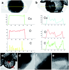 | ||
| Fig. 5 The EDX line profiles of (a) porous CuO/C and (b) 3DOM-CuO/C submicron spheres (Cu, O, and C), (c) HR-TEM images of the (d) outer and (e and f) inner surfaces of double-shelled 3DOM-CuO/C. | ||
The surface binding energy spectra in Fig. S3† also demonstrate that Cu, O, and C were presented on the surfaces of porous-CuO/C and 3DOM-CuO/C. The main peaks of the Cu 2p spectra (Cu 2p1/2 and Cu 2p3/2) were 953.23 eV and 932.08 eV for porous CuO/C submicron spheres and 953.23 eV and 933.88 eV for double-shelled 3DOM-CuO/C, respectively. The main peak in Fig. S3b† was at 529.48 eV, corresponding to the O 1s peak. Peaks were also observed at 529.1 and 530.7 eV, as shown in Fig. S3e,† and assigned to CuO and –OH, respectively. The binding energies of C 1s were 288.58 eV and 283.18 eV for porous CuO/C submicron spheres and 284.5 eV and 289 eV for double-shelled 3DOM-CuO/C. These peaks were attributed to carboxyl groups. The thin carbon layer was produced during the template removal step. Since Cu precursors were diffused into the cross-linked networks of poly(MAA/EGDMA), as mentioned above, the fragment of the polymer chain formed by the partial decomposition of poly(MAA/EGDMA) surrounded the growing CuO crystals as the temperature increased. During the temperature maintenance period, where CuO crystal growth was continuous, the aggregated, decomposing polymer chains become a thin carbon layer on the surfaces of the nano-grains of porous-CuO and 3DOM-CuO. The size of the Cu(OH)2 aggregates formed after the addition of CuSO4 solution into the alkaline mixture solution containing polymer particles is an important parameter that influences particle morphology. As mentioned above, when the CuSO4 solution was added to each aqueous solution, Cu2+ ions and solid Cu(OH)2 were formed. Due to the different pH values of the aqueous solution at the two different experimental conditions, Cu(OH)2 aggregates of different sizes were formed.11 To confirm the effects of the size of Cu precursors, we performed a series of experiments. First, the crystal sizes were measured with a zeta-potential analyzer to investigate differences in size of the Cu(OH)2 crystals in aqueous solutions at different pH values. The pH values of the aqueous solutions after dispersion of poly(MAA/EGDMA) were 7.44 and 9.05, respectively. Therefore, the initial pH values of the aqueous solutions before dispersion of polymer templates were adjusted and varied between a pH of 6 to a pH of 11 using a 3 M NaOH solution in order to emulate the experimental conditions used during the polymer template dispersion step. When the CuSO4 solution (2.6 mM, 10 ml) was poured into each aqueous solution (10 ml), only the solution with a pH of 10 became translucent. Additionally, visible, light blue aggregates were formed in the solution with a pH of 11, as shown in Fig. S4a.† The results of the crystal size measurements are displayed in Fig. S4b.† The size distribution graphs for crystal formation varied as the pH was changed. While the size distribution of Cu(OH)2 formed under an aqueous solution with a pH of 8 was on the order of 1–2 nm, the size of Cu(OH)2 crystals formed in an aqueous solution with a pH of 11 was much larger compared to those formed in the other pH conditions. The average size of Cu(OH)2 increased as the pH value increased. Additionally, the Cu(OH)2 crystals formed at a higher pH tended to be more aggregated. The Cu(OH)2 aggregates formed at a lower pH might diffuse into the poly(MAA/EGDMA) chain networks more easily. During the diffusion of Cu precursor into the polymer gel, tiny Cu(OH)2 crystals diffused into the poly(MAA/EGDMA) chain networks. After freeze-drying, the Cu(OH)2 crystals formed porous CuO spheres during heat treatment. When the Cu precursor diffused at a higher pH, smaller crystals diffused into the cross-linked network of poly(MAA/EGDMA); however, larger crystals were located in the outer portions of the poly(MAA/EGDMA) microspheres. The Cu(OH)2 crystals that were located on the surface formed the outer shell during heat treatment, and the outer shell interconnected with the continuously growing crystals on the surfaces of nearby particles. CuO crystal growth occurs on the surfaces of particles via Ostwald ripening and the simultaneous decomposition of polymer segments. During the formation of the outer shell, an interface between the outer shell and the decomposing polymer segments containing Cu(OH)2 can be generated. As a result, the inner CuO shell can also form in the interior space via interfacial reactions between oxygen molecules and the Cu(OH)2 on the surface of the decomposing polymer. The inner CuO shell grows until the polymer is completely decomposed. This potential mechanism is displayed in Fig. S5.†
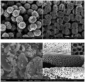
To investigate the effect of solution pH on the morphological and structural changes of CuO/C particles after heat treatment, the diffusion process of Cu precursors was analyzed at a lower and a higher pH (6.55 and 11.21) compared to those used in the original experiment (7.44 and 9.05). The same amount of CuSO4 solution (2.6 mM) was added to each aqueous solution. After freeze-drying, the pH-controlled Cu precursor-poly(MAA/EGDMA) microspheres underwent heat treatment for 2 h at 500 °C under a gaseous mixture (mainly air). The SEM and FIB-SEM images of the two types of Cu-precursor/poly(MAA/EGDMA) composite microspheres prepared under different pHs after heat treatment are shown in Fig. 6. Porous and macroporous structures were observed in Cu-precursor/poly(MAA/EGDMA) composite microspheres prepared under different pHs: a pH of 6.55 (Fig. 6a and b) and a pH of 11.21 (Fig. 6c and d), respectively. The interconnected shell of macroporous CuO/C prepared under the highest pH condition (11.21) was thicker than that of 3DOM-CuO/C prepared at a pH 9.05, and the inner shell was rarely observed. These results support the conclusion that large Cu(OH)2 aggregates formed under the strongly alkaline aqueous solution and were located on the particle surface. These aggregates were responsible for the formation of the interconnected shell and the macroporous structure after heat treatment. The existence of the inner shell in the macroporous CuO prepared under the highest pH condition (Fig. 6d inset) indicates that the Cu precursors can diffuse into the center of the poly(MAA/EGDMA) microspheres even in strong alkaline conditions. The Cu-precursor/poly(MAA/EGDMA) composite microspheres prepared under different pH conditions were characterized with HR-TEM and STEM to determine the size and distribution of the Cu precursors introduced into the polymer microspheres. The STEM images in Fig. 7 and S6† demonstrate that the nanoscale Cu-precursors were successfully diffused into poly(MAA/EGDMA) microspheres under all experimental conditions. The size of the Cu-precursors was very small, and the size and distribution of Cu precursors in the polymer chain networks with pHs of 7.44 and 9.05 were not distinguishable in STEM images. As shown in Fig. S6(a–i),† neither crystals nor aggregates were observed on the surfaces of Cu-precursor/poly(MAA/EGDMA) composite microspheres prepared at a pH of (a–c) 6.55, (d–f) 7.44, or (g–i) 9.05. At a pH of 11.21, however, some aggregates were observed on the surface of the composite microsphere, as shown in Fig. S6(m–o).† The Cu precursors were severely aggregated in the aqueous solutions with pHs of 10 and 11 in the absence of poly(MAA/EGDMA), as displayed in Fig. S4.† However, when CuSO4 solution was added into the aqueous solution with swollen polymer microspheres, Cu2+ ions and Cu(OH)2 diffused into the polymer networks by electrostatic attraction, and a severe concentration gradient was produced before aggregation. During the heat treatment, the aggregates adsorbed onto the surfaces of the interconnected, thick shell and the macroporous structures (Fig. 6d).
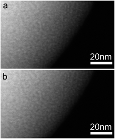 | ||
| Fig. 7 High-magnification STEM images of Cu-precursor/poly(MAA/EGDMA) composite microspheres prepared under two different pH conditions: (a) a pH of 7.44 and (b) a pH of 9.05. | ||
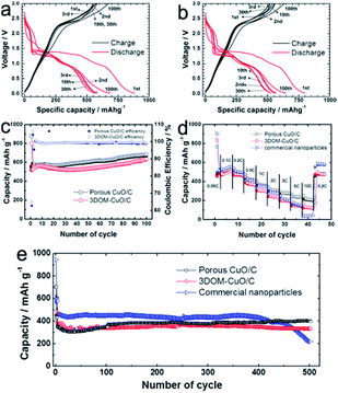
The electrochemical properties of the as-fabricated porous CuO/C and 3DOM-CuO/C composite electrodes were investigated using 2032 coin-type cells. The theoretical capacities of two types of CuO/C samples are calculated on the ratio of CuO and carbon contents. As mentioned in Fig. S2,† since the carbon amounts of porous CuO/C and double-shelled 3DOM CuO/C are 4.57 and 5.50 wt%, the similar theoretical capacities of two types of samples are applied to the electrochemical measurements. The charge–discharge voltage profiles of the 1st, 2nd, 3rd, 10th, 30th, and 100th cycles of porous CuO/C and 3DOM-CuO/C composite electrodes in the range of 0.02–3.0 V and at 0.2 C are displayed in Fig. 9a and b. The charge–discharge curves exhibit similar discharge behaviors to CuO-based anodes. The three plateaus near 1.8 V, 1.4 V, and 0.8 V at the first discharge correspond to the reductive reaction of the following equation: CuO + 2e− + 2Li+ ↔ Cu + LiO2. Additionally, the plateaus near 2.3 V and 1.5 V at the first charge curve are attributed to the following equation: 2Cu + LiO2 ↔ CuO + 2Li. The lithiation capacity of the porous CuO/C at the first cycle was 879 mA h g−1, and the reversible capacity was 558 mA h g−1. This corresponds to a Coulombic efficiency of 63% (Fig. 8a). The 2nd, 3rd, 10th, and 30th cycle capacities were between 550 mA h g−1 and 580 mA h g−1, but the capacity gradually increased and reached 681 mA h g−1 at the 100th cycle. The double-shelled 3DOM-CuO/C also exhibited similar behavior with its cycling performance test at 0.2 C. The lithiation capacity of the double-shelled 3DOM-CuO/C composite electrode at the first cycle was 798 mA h g−1, and the reversible capacity was 525 mA h g−1. This corresponds to a Coulombic efficiency of 65%. The 2nd, 3rd, 10th, and 30th cycle capacities were between 500 mA h g−1 and 550 mA h g−1, and the capacity reached 650 mA h g−1 at the final cycle. Such capacity growth has been reported in several studies of anode materials based on metal oxides. The increased capacity might be attributed to the pseudo-capacitive polymeric gel-like film produced by decomposition of the organic electrolyte at low voltage.16 Fig. 8c shows the cycling performance of the porous CuO/C and double-shelled 3DOM-CuO/C composite electrodes at a current rate of 0.2 C. Both electrodes showed high Coulombic efficiency (>99%) and similar capacity values (between 550 mA h g−1 and 600 mA h g−1). The initial irreversible capacities of both electrodes are attributed to the formation of a solid electrolyte interface (SEI) layer on the surfaces of the active materials via a side reaction with the organic electrolyte. The stable capacities of the two electrodes reached 681 mA h g−1 and 639 mA h g−1 at the 100th cycle, with the same gradual capacity increase mentioned above. This maintained capacity is attributed to the robust particle structure to diffuse Li ions during lithiation–delithiation processes. After 100 cycles, the structures of the electrodes were investigated using focused ion beam (FIB)–SEM. Both the porous and double-shelled 3DOM structures were well-maintained after 100 cycles at a current rate of 0.2 C (Fig. S7†). As shown in Fig. S7a,† pores were observed throughout the porous spheres. The inner shells, outer shells, and void space of double-shelled 3DOM-CuO/C were also observed, as shown in cross-sectional SEM images of the electrodes (Fig. S7b†). Therefore, we assumed that the thin carbon layers of porous CuO/C submicron spheres and double-shelled 3DOM-CuO/C accommodated the transformation and volume expansion of CuO during lithiation. The rate performance of both electrodes, containing two types of CuO/C particles and commercial CuO nanoparticles, was evaluated at various current rates in the voltage range between 0.02 and 3.0 V (Fig. 8d). The first discharge capacity of the commercial CuO electrode was the highest: 904 mA h g−1. The capacities of the three types of electrodes between 0.1 and 0.5 C are similar, but there is a noticeable gap in capacity at higher rates. In particular, the capacity of the composite electrode with the commercial CuO nanoparticles decreased significantly at the current rate of 10 C due to nanoparticle aggregation during continuous cycling. These different capacities at higher current rates are attributed to the different surface areas of porous CuO/C and double-shelled 3DOM-CuO/C. The porous CuO/C and double-shelled 3DOM-CuO/C composite electrodes also showed good capacity retention with high Coulombic efficiency even at a higher rate (1 C) with long cycling, compared to commercial CuO nanoparticles, as shown in Fig. 8e. While the discharge capacity of the porous CuO/C composite electrode was 398 mA h g−1 at the 500th cycle, the double-shelled 3DOM-CuO/C composite electrode exhibited a relatively lower capacity of 334 mA h g−1. Initially, the discharge capacity of the commercial CuO electrode was greater than 450 mA h g−1, but the capacity decreased rapidly after the 400th cycle. Compared to other hierarchical CuO materials,18 the our CuO/C anodes exhibit better cyclability during very long cycles due to the robust structure and very thin carbon layer coated on the surface of CuO nanograins. In addition, the uniform particle size and macroporous structure can show fast reaction kinetics.
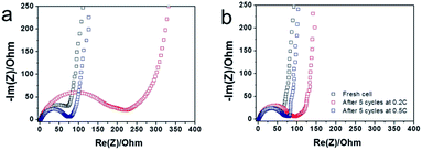
The kinetics of the charge transfer reaction of porous CuO/C and double-shelled 3DOM-CuO/C composite electrodes were investigated with electrochemical impedance spectroscopy (EIS). Nyquist plots of the electrochemical impedance spectra obtained from the porous CuO/C and double-shelled 3DOM-CuO/C after cycling at different current rates (before cycling, 0.2 C, and 0.5 C) in the fifth cycle are shown in Fig. 9. The radii of the semi-circles at high frequency changed drastically with the cycling current rate. The porous CuO/C composite electrode showed a larger semi-circle radius in the middle frequency range compared to the double-shelled 3DOM-CuO/C. These results suggest that the 3DOM-CuO/C particles had a lower charge transfer resistance (Rct) compared to the porous CuO/C submicron spheres due to their hollow structure. After the fifth discharge at a current rate of 0.2 C, the semi-circular sizes of both electrodes increased. The semi-circle of the porous CuO/C, in particular, showed a significant change. After the fifth discharge at a current rate of 0.5 C, however, the sizes of the semi-circles for the two samples were similar. Lithium ions might have been inserted into the CuO grains of the porous structured spheres more regularly at slower current rates compared with the bulk 3DOM structures. The charge transfer resistance of commercial CuO electrode is higher than those of two types of CuO/C samples, as shown in Fig. S8.† This result indicates that the thin carbon layer contributed to the long cycling ability and high rate capability as indicated by a decrease in the overall internal resistance of cells.
Conclusions
In conclusion, we simply prepared porous CuO/C submicron spheres and 3DOM-CuO/C using ionizable polymer microspheres as a sacrificial template. The internal structure depended on the size of the Cu precursors in the mixture solution as the pH value changed. Diffusion of the Cu precursors into the poly(MAA/EGDMA) networks was investigated with TGA and STEM. After heat treatment, under a certain gaseous atmosphere, thin carbon layers (∼2 nm thick) formed on the surfaces of the inner/outer shells. These layers were characterized using HR-TEM and EDX line profiles. As anode materials for lithium ion batteries, porous CuO/C and the double-shelled 3DOM-CuO/C composite electrodes show good capacity retention with high Coulombic efficiency, even at high current rates, compared with commercial CuO nanoparticles. At a rate of 1 C, both electrodes maintained their capacity up to the 500th cycle without any capacity fading. These enhanced electrochemical performances are attributed to the 3D structure, which includes a cavity space and a thin carbon layer. These factors accommodate volume variation during lithiation–delithiation processes and reduce the charge-transfer resistance. We expect that our experimental system can be expanded and generalized for the synthesis of a series of metal oxides with novel and varied structures.Acknowledgements
This work was supported by a grant of the Human resources Development Program of KETEP, funded by the Ministry of Trade, Industry and Energy of Korea (no. 20124010203290). This work was supported by the Global Frontier R&D Program (2013M3A6B1078875) on Center for Hybrid Interface Materials (HIM) funded by the Ministry of Science, ICT & Future Planning.Notes and references
- W. M. Zhang, X. L. Wu, J. S. Hu, Y. G. Guo and L. J. Wan, Adv. Funct. Mater., 2008, 18, 3941 CrossRef CAS.
- (a) X. Zhu, Y. Zhu, S. Murali, M. D. Stoller and R. S. Ruoff, ACS Nano, 2011, 5, 3333 CrossRef CAS PubMed; (b) S. Yang, G. Cui, S. Pang, Q. Cao, U. Kolb, X. Feng, J. Maier and K. Mullen, ChemSusChem, 2010, 3, 236 CrossRef CAS PubMed.
- H. B. Wu, J. S. Chen, H. H. Hng and X. W. lou, Nanoscale, 2012, 4, 2526 RSC.
- Z. Yang, J. Shen and L. A. Archer, J. Mater. Chem., 2011, 21, 11092 RSC.
- C. Ki, M. Noh, M. Choi, J. Cho and B. Park, Chem. Mater., 2005, 17, 3297 CrossRef.
- X. P. Gao, J. L. Bao, G. L. Pan, H. Y. Zhu, P. X. Huang, F. Wu and D. Y. Song, J. Phys. Chem. B, 2004, 108, 5547 CrossRef CAS.
- S. Chaudhari and M. Srinivasan, J. Mater. Chem., 2012, 22, 23049 RSC.
- (a) R. Sahay, P. S. Kumar, V. Aravindan, J. Sundaramurthy, W. C. Ling, S. G. Mhaisalkar, S. Ramakrishna and S. Madhavi, J. Phys. Chem. C, 2012, 116, 18087 CrossRef CAS; (b) D. P. Singh, A. K. Ojha and O. N. Srivastava, J. Phys. Chem., 2009, 113, 3409 CrossRef CAS; (c) J. Y. Xiang, J. P. Tu, L. Zhang, Y. Zhou, X. L. Wang and S. J. Shi, J. Power Sources, 2010, 195, 313 CrossRef CAS PubMed.
- (a) X. W. Lou, C. M. Li and L. A. Archer, Adv. Mater., 2009, 21, 2536 CrossRef CAS; (b) J. E. Lee, S. H. Yu, D. J. Lee, D. C. Lee, S. I. Han, Y. E. Sung and T. Hyeon, Energy Environ. Sci., 2012, 5, 9528 RSC.
- (a) T. Zhu, J. S. Chen and X. W. Lou, J. Phys. Chem. C, 2011, 115, 9814 CrossRef CAS; (b) Y. Li, S. Zhu, Q. Liu, J. Gu, Z. Guo, Z. Chen, C. Feng, D. Zhang and W. J. Moon, J. Mater. Chem., 2012, 22, 2766 RSC; (c) X. Jia, Z. Chen, X. Cui, Y. Peng, X. Wang, G. Wang, F. Wei and Y. Lu, ACS Nano, 2012, 6, 9911 CrossRef CAS PubMed.
- (a) W. Wang and P. N. Kumta, ACS Nano, 2010, 4, 2233 CrossRef CAS PubMed; (b) Z. S. Wen, J. Yang, B. F. Wang, K. Wang and Y. Liu, Electrochem. Commun., 2003, 5, 165 CrossRef CAS; (c) K. Chang, W. Chen, L. Ma, H. Li, H. Li, F. Huang, Z. Xu, Q. Zhang and J. Y. Lee, J. Mater. Chem., 2011, 21, 6251 RSC; (d) G. Du, C. Zhong, P. Zhang, Z. Guo, Z. Chen and H. Liu, Electrochim. Acta, 2010, 55, 2582 CrossRef CAS PubMed.
- (a) X. Xu, R. Cao, S. Jeong and J. Cho, Nano Lett., 2012, 12, 4988 CrossRef CAS PubMed; (b) H. S. Lim, B. Y. Jung, Y. K. Sun and K. D. Suh, Electrochim. Acta, 2012, 75, 123 CrossRef CAS PubMed.
- H. S. Lim, Y. K. Sun and K. D. Suh, J. Mater. Chem. A, 2013, 1, 10107 CAS.
- (a) S. F. Zheng, J. S. Hu, L. S. Zhong, W. G. Song, L. J. Wan and Y. G. GuO, Chem. Mater., 2008, 20, 3617 CrossRef CAS; (b) H. Wang, Q. Pan, J. Zhao and W. Chen, J. Alloys Compd., 2009, 476, 408 CrossRef CAS PubMed; (c) B. Wang, X. L. Wu, C. Y. Shu, Y. G. Guo and C. R. Wang, J. Mater. Chem., 2010, 20, 10661 RSC; (d) X. H. Huang, C. B. Wang, S. Y. Zhang and F. Zhou, Electrochim. Acta, 2011, 56, 6752 CrossRef CAS PubMed; (e) X. Liu, Z. Li, Q. Zhang, F. Li and T. Kong, Mater. Lett., 2012, 80, 37 CrossRef CAS PubMed; (f) Z. Yin, Y. Ding, Q. Zheng and L. Guan, Electrochem. Commun., 2012, 20, 40 CrossRef CAS PubMed.
- R. Abu-Much, U. Meridor, A. Frydman and A. Hedanken, J. Phys. Chem. B, 2006, 8194 CrossRef CAS PubMed.
- Y. Xu, J. Guo and C. Wang, J. Mater. Chem., 2012, 22, 9562 RSC.
- F. Bai, B. Huang, X. Yang and W. Huang, Eur. Polym. J., 2007, 43, 3923 CrossRef CAS PubMed.
- (a) W. Zhang, M. Li, Q. Wang, G. Chen, M. Kong, Z. Yang and S. Mann, Adv. Funct. Mater., 2011, 21, 3516 CrossRef CAS; (b) J. Y. Xiang, J. P. Tu, L. Zhang, Y. Zhou, X. L. Wang and S. J. Shi, Electrochim. Acta, 2010, 55, 1820 CrossRef CAS PubMed.
Footnotes |
| † Electronic supplementary information (ESI) available: FT-IR spectrum and OM images of poly(MAA/EGDMA) microspheres. The analyzed amounts of Cu, O and C in samples are displayed. XPS spectra of CuO/C composite particles. Digital photographs of bials and particle size distribution data of Cu precursors without poly(MAA/EGDMA) microspheres. Schematic illustration of the formation mechanism of two types of CuO composite particles. HR-TEM images of Cu precursors/poly(MAA/EGDMA) composite microspheres prepared under different pH conditions. Cross-sectional SEM images of composite electrodes containing two types of CuO/C composite particles after 100 cycles. EIS of fresh cells containing two types of CuO/C samples and commercial CuO nanoparticles. See DOI: 10.1039/c4ra09648g |
| ‡ These authors contributed equally to this work. |
| This journal is © The Royal Society of Chemistry 2014 |


