Liquid crystal microphase separation of cellulose nanocrystals in wet-spun PVA composite fibers
Dagang Liu*a,
Jinlei Lia,
Fengxiang Suna,
Ruimin Xiaoa,
Yi Guob and
Jianwei Songa
aDepartment of Chemistry, Nanjing University of Information Science & Technology, Nanjing, 210044, China. E-mail: dagangliu@gmail.com; Fax: +86 2558731090; Tel: +86 2558731090
bDepartment of Chemistry and Chemical Engineering, Wuhan Textile University, Wuhan, 430073, China
First published on 19th June 2014
Abstract
Remarkable mechanical performance and chiral nematic liquid crystal behavior make sulfate cellulose nanocrystals (CNCs) attractive for many researchers. However, CNCs at a low content in the composite lost their liquid crystal characters because the lyotropic mesogens of rod-like negative-charged CNCs were easily affected by external forces, such as hydrogen bonding interactions with poly(vinyl alcohol) (PVA) in the composite. In present study, the electrolyte, sodium sulfate, was introduced to induce nematic mesophases of CNCs during the coagulation process of wet-spun PVA/CNCs composite fibers. We investigated the morphology, structure and mechanical properties of the spun fiber and hypothesized a scheme to establish the mechanism of formation for the liquid crystal domain and illustrate the specific mechanical properties caused by the resultant phase separation. The recognized ionic induction effects will be quite helpful to fabricate functional liquid crystal fabrics for future industrial applications.
1. Introduction
Cellulose nanocrystals (CNCs) prepared from the acidic hydrolysis of cellulose have gained the interest of researchers worldwide for their remarkable mechanical properties, e.g., the elastic modulus of CNCs was estimated to be 80–150 GPa in the axial direction and 10–50 GPa in the transverse direction.1–4 Furthermore, CNCs are environmental friendly because of their non-toxic, biocompatible, and biodegradable nature. Recently, employing CNCs as nanofillers to improve the mechanical properties of polymer matrices has become of particular interest,5 therefore, CNCs have been successfully incorporated into many polymers fibers as highly effectively reinforcement nanofillers including: poly(lactic acid) (PLA),6 starch,7 polycaprolactone (PCL),8 alginate,9 and polyethylene oxide (PEO).10 To our knowledge, there are few reports concentrating on the liquid crystal orientation of CNCs used as a reinforcement filler.Recently, aqueous suspensions of CNCs prepared by sulfuric acid hydrolysis were reported to assemble into chiral nematic or cholesteric liquid crystalline mesophases above a critical concentration; moreover, the film cast from these liquid crystalline suspensions could inherit a regular chiral nematic orientation.11 Hence, the liquid-crystalline behavior of CNCs suspensions is fascinating and offers a novel route to induce the alignment of CNCs.12 Therefore, many inorganic (SiO2) or organic (PSt) fillers were introduced into CNC mesogens to fabricate the iridescent composites or porous photonic crystal materials.13–15 Cheung et al.16 prepared CNCs/polymer composites by casting the dispersion of CNCs with a suitable polymer (<50 wt%) soluble in the organic solvent used and demonstrated that these iridescent composite films with a little bit electrolyte showed a layered, nematic-like morphology indicative of a lyotropic organization of CNCs. Therefore, the dispersion state, weight ratio and the phase behavior of CNCs played significant roles in the optical, mechanical, and thermal performance of CNC composites.
It has been proved that fibers spun from liquid-crystal solutions can achieve high orientation,17–19 e.g., Kevlar fibers with ultra-high strength and stiffness were produced by spinning from lyotropic liquid-crystal solutions of rigid-rod macromolecules. Nevertheless, it is still a challenge to achieve fibers directly from CNCs suspension for the intrinsic rigidity of CNC rods. Poly(vinyl alcohol) (PVA) is a commercially important hydrophilic polymer featuring many outstanding properties,20 e.g., good fiber forming, thus leading to its important applications in the fabric industry.21 In our previous work, cellulose nanofibrils exhibited a high affinity to hydrophilic PVA so that the nanofibrils effectively improved the mechanical performance and water resistance of matrices.22 In this work, CNCs were introduced into PVA to fabricate a series of composite fibers by a wet-spinning process. On one hand, we hope to understand the effect of CNCs on the structural properties of PVA based fibers; on the other hand, we anticipated to build up a new approach to induce the liquid crystalline mesophases of CNCs in a fibrous PVA matrix using a salt coagulant via a wet-spinning process.
2. Experimental section
2.1 Materials
Microcrystalline cellulose (MCC) powder was obtained from Sinopharm Co. (Shanghai, China) and was selected as the raw material for producing CNCs. PVA, having a degree of polymerization (DP) of about 2600 and saponification of 98%, was purchased from the same supplier and used without further purification to prepare the aqueous solutions for wet-spinning.2.2 Preparation of CNCs
CNCs were prepared according to a method described in our previous work.11 Briefly, MCC powder was dispersed in 64 wt% sulfuric acid at 45 °C for 2 h under vigorous stirring. Immediately, five folds of distilled water were applied to quench the hydrolysis reaction. The resulting dispersion was then poured in to dialysis tubing (MWCO = 8000–12![[thin space (1/6-em)]](https://www.rsc.org/images/entities/char_2009.gif) 000) and dialyzed against distilled water until the pH of the water reached a constant value of 5.0–5.5. After dialysis, the dispersion was processed through a high-pressure homogenizer (M-100P, Microfluidics, USA), which was equipped with a Y-shaped diamond interaction chamber (65 μm) for 10 cycles. Finally, the stable suspension was stored in a refrigerator at 10 °C prior to use.
000) and dialyzed against distilled water until the pH of the water reached a constant value of 5.0–5.5. After dialysis, the dispersion was processed through a high-pressure homogenizer (M-100P, Microfluidics, USA), which was equipped with a Y-shaped diamond interaction chamber (65 μm) for 10 cycles. Finally, the stable suspension was stored in a refrigerator at 10 °C prior to use.
2.3 Wet-spinning of PVA/CNCs fibers
PVA was dissolved in distilled water to obtain a 15 wt% aqueous solution at 90 °C for 2 h under vigorous stirring. After cooling to room temperature, a certain amount of CNC suspension with a concentration of 3.2 wt% was added to the freshly prepared PVA solution. The mixture was agitated to obtain a homogeneous dispersion at room temperature for 30 min. The resultant dispersion was then transferred to a refrigerator and allowed a slow self-organization of the components at 10 °C for at least one month to obtain a spinning dope with a suitable concentration of 15–20 wt%. Then the spinning dope was extruded from a 10 mL plastic syringe into a coagulating bath containing saturated sodium sulfate solution at 45 °C. The as-spun fibers were repeatedly washed with distilled water to remove the residual salt, and then air-dried for 24 h and stored in a desiccator prior to characterization. The blend fibers were coded as PVA/CNC1, PVA/CNC3, PVA/CNC5, PVA/CNC8, PVA/CNC10, and PVA/CNC20, corresponding to the loading percentage of CNCs in the composite fibers at 1, 3, 5, 8, 10, and 20 wt%, respectively. The pure PVA fiber prepared in the absence of CNCs was coded as PVA.2.4 Characterization
The dimensions of CNCs were determined by atomic force microscopy (AFM) using an Asylum Research MFP-3D atomic force microscope (Santa Barbara, CA). A representative sample of the CNC suspension was diluted into ∼0.1 wt% and then a few drops of the diluted suspension were spin-coated onto freshly cleaned silicon wafer chips. The sample on the chips was allowed to dry and then scanned in a AC tapping mode with Tap 300 standard silicon probes (tip radius <10 nm, spring constant = 37 N m−1, resonant frequency = 300 kHz) (Budget Sensor, USA) at a scan rate of 1 Hz and an image resolution of 1024 pixels × 1024 pixels. Liquid crystal phase observation was performed on a polarized optical microscope (POM; LV100POL, Nikon, Japan). Suspensions of CNCs and PVA/CNCs were dropped on a glass slide and then observed at room temperature. The PVA/CNCs composite fibers and film were also observed using POM under the same conditions.Wide-angle X-ray diffraction (XRD) measurements were carried out on a X-ray diffractometer (XRD-6100, Bruker Siemens, Japan) with a Nickel-filtered Cu Kα radiation (λ = 1.524 Å) source at 40 kV and 30 mA. X-ray diffraction data were collected from 2θ = 4 to 60° at a scanning rate of 2° min−1, at room temperature. Tensile properties of the nanocomposite fibers with an average length of 20 mm were measured on a LLY-06 tensile tester (Laizhou Electronic Instruments, China) at a crosshead speed of 20 mm min−1. The testing results were evaluated as the average of at least 50 measurements. The cross-section (or fractured surface) and surface of fibers were sputter-coated with gold, and then observed and photographed on an S-4700 scanning electron microscope (SEM; Hitachi, Japan) with an accelerating voltage of 20 kV.
3. Results and discussion
3.1 Liquid crystal mesophases of CNCs
Fig. 1a shows the AFM images of CNCs whose size typically varied from 160 to 210 nm in length and 30 to 35 nm in width. The calculated aspect ratio was 5.5–7. CNCs prepared by sulfuric acid hydrolysis behaved as a lyotropic liquid crystal while its concentration crept above the critical concentration in aqueous suspension because of the repulsion caused by the negative charged surface of the sulfate groups. As shown in Fig. 1b, chiral nematic liquid crystal phases with highly ordered arrangement of fingerprints were observed in the suspension at a concentration of 2 wt%. However, the spinning dope or casting film of PVA/CNC5 (Fig. 1c and d) did not inherit the cholesteric mesophases and orientation of cellulosic nanocrystal colloids, probably because the good compatibility and affinity between PVA and CNCs drove those CNCs to disaggregate from each other and homogeneously dispersed in the PVA matrix. We hypothesized that two approaches should be adopted to induce the liquid crystal mesophases of CNCs, by either reducing the affinity between the CNCs and PVA caused by hydrogen bonding interactions or increasing the degree of aggregation in the CNC particles.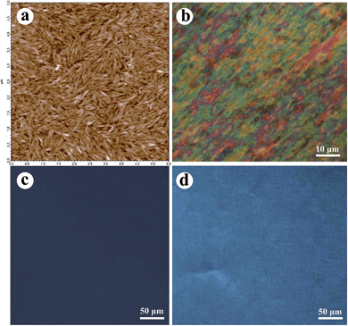 | ||
| Fig. 1 AFM image of CNCs (a). POM micrographs of the CNCs suspensions (b), 5 wt% suspensions of PVA/CNCs (c) and the film cast from the 5 wt% suspensions of PVA/CNCs (d). | ||
3.2 Structure and morphology of PVA/CNCs fibers
Fig. 2 shows the typical photograph and SEM micrograph of the PVA/CNC5 fiber. The PVA/CNCs composite fibers, irrespective of the CNCs content, comprised white, smooth, and uniform filaments and the exterior surface of the composite fibers was absent of salt.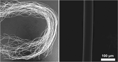 | ||
| Fig. 2 Photographs of the wet-spun PVA/CNC5 (left) and SEM micrographs of the exterior surface of PVA/CNC5 after repeatedly washing with water (right). | ||
The crystalline structures of neat PVA fibers and composite fibers with various CNCs contents are shown in Fig. 3. The diffraction pattern of neat PVA fiber exhibited a typical crystalline peak at 2θ = 19.8°, corresponding to the (101) plane of semicrystalline PVA.23 This characteristic diffraction peak of PVA also appeared in the diffraction patterns of all the composite fibers, suggesting that the crystal structure of PVA was essentially maintained even with the introduction of CNCs.24 Meanwhile, a new diffraction peak arose at 2θ = 22.5°, indicating the presence of CNCs since the primary peak around 2θ = 22.5° was attributed to the (200) plane of cellulose I.25 Moreover, the intensity of the peak at 2θ = 22.5° increased with an increasing content of CNCs. However, in the case of PVA/CNC10, the incorporation of 10 wt% CNCs into PVA resulted in the presence of two characteristic diffraction peaks at 2θ = 32° and 34.2°, ascribed to the (200) and (130) crystalline planes of sodium sulfate, respectively.26 That is to say, many sodium and sulfate ions merged into the composites during the spinning process, and formed crystals after drying. The degree of crystallinity (W) could be evaluated using the following equation:
| W = 100(S/So) | (1) |
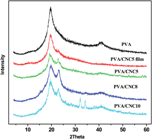 | ||
| Fig. 3 XRD patterns of neat PVA, PVA/CNC5, PVA/CNC8, PVA/CNC10 and the film cast from the PVA/CNC5 suspension. | ||
Fig. 4 shows the POM micrographs of PVA and the PVA/CNCs composite fibers. Both the neat PVA and PVA/CNCs composite fibers had a certain content of stretch orientation due to the stretching force applied during the spinning process. Neat PVA fiber (Fig. 4a) was uniform under polarized light, indicating no liquid crystal anisotropy.27 With the incorporation of CNCs, the emergence of distinct bright and iridescent domains could be observed along the long axis of the PVA/CNCs composite fibers (Fig. 4b–f). Moreover, with an increasing proportion of CNCs loaded into the fibers, PVA/CNC10 (Fig. 4e) and PVA/CNC20 (Fig. 4f) show distinct microscopic birefringence, which was ascribed to the anisotropy properties and the strong birefringence of CNCs under the polarized light, which was not observed from PVA/CNCs suspensions or casting films as mentioned in Fig. 1c and d. It is well known that CNCs behave like a polyelectrolyte as a result from the sum of negatively charged sulfate ester groups. While neutral electrolytes, such as NaCl or Na2SO4 were added, the original phase equilibrium of CNCs was broken and anisotropic phase formation suppressed because the increase in ionic strength would screen the electrostatic double layers. Asako et al.28 proposed that the existence of NaCl was conducive to the formation of liquid crystals for CNCs. A similar case was reported by Gray et al. in which anionic or cationic dye molecules would also cause phase separation.29 In the coagulating process, sodium sulfate was selected as the coagulation agent, in which sodium and sulfate ions drove CNCs via electrostatic forces to aggregate and organize into the heterogeneously distributed mesophases.30 Without any doubt, ionic effects had greatly contributed to the formation of a liquid crystalline phase of CNCs and phase separation between PVA and CNCs.
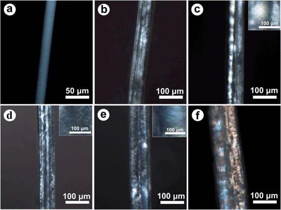 | ||
| Fig. 4 POM micrographs of PVA (a), PVA/CNC3 (b), PVA/CNC5 (c), PVA/CNC8 (d), PVA/CNC10 (e) and PVA/CNC20 (f). | ||
3.3 Mechanical properties of PVA/CNCs fibers
The tensile behavior of the neat PVA and PVA/CNCs composite fibers are shown in Fig. 5. As a semicrystalline polymer, PVA fiber presents a tensile strength of 0.1776 cN dTex−1 and strain of 157.59%. CNCs exhibited a strong reinforcement effect on all the composite fibers because of the rigid nature of the CNC fillers. However, it is interesting that the tensile strain exhibited almost the same trend as the stress varying with loadings of CNCs, especially when the content of CNCs increased from 0–5 wt%, the elongation at break simultaneously increased. Amongst all the composite fibers, PVA/CNC5 showed the highest tensile strength, strain, and modulus, which were 305%, 270.6% and 222.9% higher than that of neat PVA, respectively, indicating good reinforcement and toughening effects. When the CNC content was above 5 wt%, the tensile stress and strain of the PVA/CNCs simultaneously decreased, which may be caused by an excessive phase separation and immigration of salt, especially in the case of PVA/CNC20, which was too brittle to be mechanically measured. The morphology of the fractured surfaces of both PVA and PVA/CNCs fibers are displayed in Fig. 6. The cross-section of neat PVA fiber (Fig. 6a) was kidney shaped and its fracture surface was smoother than that of the composite fibers (Fig. 6b–e). In the case of PVA/CNC5, the tensile fracture showed fibrillation morphs (Fig. 6c) and presented a certain degree of orientation in the fiber axes, indicating that the assembled nematic liquid crystals of CNCs were highly oriented along the fiber long-axis during the process of uniaxial drawing, thus leading to an increase of tensile stress and strain simultaneously. Observed from the fracture surface, PVA/CNC10 and PVA/CNC20 exhibited a brittle nature although fibrous bundles still could be found as shown in the inset of Fig. 6f, indicating that lots of CNC bundles lost their connection with PVA because of excessive phase separation caused by the electrolytes of sodium sulfate.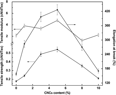 | ||
| Fig. 5 Tensile strength (●), tensile modulus (○), and elongation at break (◆) of PVA and PVA/CNCs composite fibers. | ||
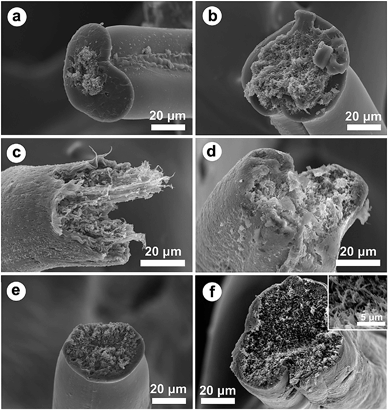 | ||
| Fig. 6 SEM micrographs of the fracture surfaces of PVA (a) and composite fibers of PVA/CNC3 (b), PVA/CNC5 (c), PVA/CNC8 (d), PVA/CNC10 (e) and PVA/CNC20 (f). | ||
Based on the above observations and measurements, we could confirm our hypothesis according to Scheme 1. CNCs could homogenously disperse in the aqueous PVA spinning dopes. However, when they met sodium sulfate in the coagulation bath, the sodium ions were drawn into spinning dopes owing to strong ionic attractions from the negatively charged sulfate ester groups of CNCs; meanwhile, water was repelled to get rid of the dope and diffuse into the saturated salt bath to form a hydrate with sodium sulfate, as a result CNCs were driven to come close to each other and orderly packed together to form chiral nematic mesophases by mechanical shear stretching.31 In addition, the PVA chains were also stretched. Without any doubt, proper phase separation caused by rigid mesogens of CNCs was beneficial for improving the mechanical strength of the composite fiber because the liquid crystalline mesophase acted as a hard domain; on the other hand, fibrillar hierarchical mesophases of CNCs would also produce a second orientation during the stretching process, thus leading to an extended elongation at break. It was thought that good synergistic effects were a result of the introduction of a proper amount of nematic mesophases. However, if the content of CNCs was high enough, lots of salt would merge into the spinning-dope and completely isolate the CNCs from PVA, that is, the soft domain of PVA would lose contact with the hard domain of the liquid crystal CNCs at the expense of tensile strength and strain. Therefore, the structure and properties of the composite fibers was highly dependent on the ionic induction and the aggregation of the nematic mesophases of CNCs incorporated into the PVA matrix.
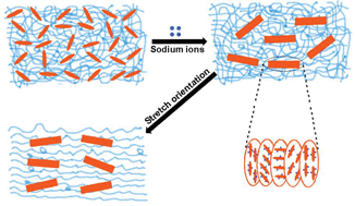 | ||
| Scheme 1 Schematic illustration of the nematic phase formation and separation of CNCs during the coagulation process. | ||
4. Conclusions
PVA/CNCs composite fibers were wet-spun using sodium sulfate as a coagulant. 5 wt% CNCs have a remarkable reinforcement and toughening effects on PVA fibers, e.g., the tensile strength, modulus, and strain was improved by 205.1%, 170.6% and 122.9%, respectively, in comparison to neat PVA fiber. The specific mechanical properties were found to be related to the phase structure of CNCs, that is, during the spinning process, the nematic liquid crystalline mesophases of CNCs were due to the combination effects of ionic induction and stretching orientation. On the contrary, over-loading nematic mesophases of CNCs would result in negative effects due to the severe phase separation between the soft domain of PVA and the hard domain of CNC mesogens. However, the as-spun composite fibers did not show the iridescent color present in the chiral nematic liquid crystal films of CNCs, perhaps because of the non-continuous dispersion of the mesophases of CNCs. In the future, more works should be concentrated on the iridescent fiber fabricated from continuous mesogens of CNCs.Acknowledgements
The authors are grateful to the National Natural Science Foundation of China (no. 51103073 and 21277073), Natural Science Foundation of Jiangsu Province (no. BK2011828), Scientific Research Foundation for the Returned Overseas Chinese Scholars, and Qing Lan Project and Six Talented Peak Program of Jiangsu Province for financial support. The Support Program of the Priority Academic Program Development of Jiangsu Higher Education Institutions is also acknowledged.References
- Y. Habibi, L. A. Lucia and O. J. Rojas, Chem. Rev., 2010, 110(6), 3479–3500 CrossRef CAS PubMed.
- P. Lu and Y. L. Hsieh, Carbohydr. Polym., 2010, 82(2), 329–336 CrossRef CAS PubMed.
- R. R. Lahiji, X. Xu, R. Reifenberger, A. Raman, A. Rudie and R. J. Moon, Langmuir, 2010, 26(6), 4480–4488 CrossRef CAS PubMed.
- C. Zhou, Q. Wu, Y. Yue and Q. Zhang, J. Colloid Interface Sci., 2011, 353(1), 116–123 CrossRef CAS PubMed.
- C. Zhou, R. Chu, R. Wu and Q. Wu, Biomacromolecules, 2011, 12(7), 2617–2625 CrossRef CAS PubMed.
- P. Lu and Y. L. Hsieh, Nanotechnology, 2009, 20(41), 415604 CrossRef PubMed.
- D. Liu, T. Zhong, P. R. Chang, K. Li and Q. Wu, Bioresour. Technol., 2010, 101(7), 2529–2536 CrossRef CAS PubMed.
- Y. Habibi, A. L. Goffin, N. Schiltz, E. Duquesne, P. Dubois and A. Dufresne, J. Mater. Chem., 2008, 18(41), 5002–5010 RSC.
- E. E. Urena-Benavides, P. J. Brown and C. L. Kitchens, Langmuir, 2010, 26(17), 14263–14270 CrossRef CAS PubMed.
- W. I. Park, M. Park, H. S. Kim and H. J. Jin, Macromol. Symp., 2007, 249(1), 289–294 CrossRef.
- D. Liu, X. Chen, Y. Yue, M. Chen and Q. Wu, Carbohydr. Polym., 2011, 84(1), 316–322 CrossRef CAS PubMed.
- N. Lin, J. Huang and A. Dufresne, Nanoscale, 2012, 4(11), 3274–3294 RSC.
- K. E. Shopsowitz, W. Y. Hamad and M. J. MacLachlan, Angew. Chem., Int. Ed., 2011, 50(46), 10991–10995 CrossRef CAS PubMed.
- M. K. Khan, M. Giese, M. Yu, J. A. Kelly, W. Y. Hamad and M. J. Maclachlan, Angew. Chem., Int. Ed., 2013, 52(34), 8921–8924 CrossRef CAS PubMed.
- M. Giese, J. C. De Witt, K. E. Shopsowitz, A. P. Manning, R. Y. Dong, C. A. Michal and M. J. Maclachlan, ACS Appl. Mater. Interfaces, 2013, 5(15), 6854–6859 CAS.
- C. C. Cheung, M. Giese, J. A. Kelly, W. Y. Hamad and M. J. Maclachlan, ACS Macro Lett., 2013, 2(11), 1016–1020 CrossRef CAS.
- R. Wang, J. Sun and L. Gao, J. Phys. Chem. C, 2010, 114(11), 4923–4928 CAS.
- Z. Xu, H. Sun, X. Zhao and C. Gao, Adv. Mater., 2013, 25(2), 188–193 CrossRef CAS PubMed.
- Z. Xu and C. Gao, Nat. Commun., 2011, 2, 571 CrossRef PubMed.
- D. K. Buslov, N. I. Sushko and O. N. Tretinnikov, Polym. Sci., Ser. A, 2011, 53(12), 1121–1127 CrossRef CAS.
- G. Du, L. Liu, Z. Song, Z. Hua, Y. Zhu and J. Chen, Biotechnol. J., 2007, 2(6), 752–758 CrossRef CAS PubMed.
- D. Liu, X. Sun, H. Tian, S. Maiti and Z. S. Ma, Cellulose, 2013, 20(6), 2981–2989 CrossRef CAS PubMed.
- A. J. Uddin, M. Fujie, S. Sembo and Y. Gotoh, Carbohydr. Polym., 2012, 87(1), 799–805 CrossRef CAS PubMed.
- C. Shao, H. Kim, J. Gong and D. Lee, Nanotechnology, 2002, 13(5), 635 CrossRef CAS.
- H. Qi, J. Cai, L. Zhang and S. Kuga, Biomacromolecules, 2009, 10(6), 1597–1602 CrossRef CAS PubMed.
- Y. C. Pu, J. R. Hwu, W. C. Su, D. B. Shieh, Y. Tzeng and C. S. Yeh, J. Am. Chem. Soc., 2006, 128(35), 11606–11611 CrossRef CAS PubMed.
- R. J. Moon, A. Martini, J. Nairn, J. Simonsen and J. Youngblood, Chem. Soc. Rev., 2011, 40(7), 3941–3994 RSC.
- A. Hirai, O. Inui, F. Horii and M. Tsuji, Langmuir, 2008, 25(1), 497–502 CrossRef PubMed.
- J. Majoinen, E. Kontturi, O. Ikkala and D. G. Gray, Cellulose, 2012, 19(5), 1599–1605 CrossRef CAS PubMed.
- S. Beck-Candanedo, D. Viet and D. G. Gray, Cellulose, 2006, 13(6), 629–635 CrossRef CAS.
- J. Ge, Y. Hu and Y. Yin, Angew. Chem., 2007, 119(39), 7572–7575 CrossRef.
| This journal is © The Royal Society of Chemistry 2014 |
