Preparation and utility of a self-lubricating & anti-wear graphene oxide/nano-polytetrafluoroethylene hybrid†
Ting Huanga,
Tongsheng Li*a,
Yuanshi Xina,
Bocheng Jinb,
Zhongxin Chena,
Chao Sua,
Haiming Chena and
Steven Nuttb
aState Key Laboratory of Molecular Engineering of Polymers, Department of Macromolecular Science, Fudan University, 220 Handan Road, Shanghai, 200433, China. E-mail: lits@fudan.edu.cn; Fax: +86-21-5163 0401; Tel: +86-21-5163 0401
bDepartment of Chemical Engineering and Materials Science, University of Southern California, Los Angeles, CA 90089-0241, USA
First published on 15th April 2014
Abstract
We design a feasible approach to prepare a self-lubricating and anti-wear graphene oxide/nano-polytetrafluoroethylene (GO/nano-PTFE, abbreviated GNF) hybrid additive by chemical compounding as a novel nano-solid lubricant. This proposal is to overcome the high friction coefficient of GO/polymer specimens for further increase in wear resistance. To explore the utility of GNF, it was incorporated into polyimide (PI) and epoxy (EP) matrices to yield GNF/PI and GNF/EP composites. The tribological properties and mechanism of GNF/polymer composites were investigated in detail. A nearly 60% reduction in friction coefficient and more than two orders of magnitude reduction in wear rate were obtained in both GNF/PI and GNF/EP composites with only 1 wt% GNF addition. Compared with unfilled polymers or polymers with individual fillers, the major increase in tribological properties of the GNF/polymer composites shows the synergy effect between nano-PTFE and GO. The increased tribological properties can be ascribed to four aspects: homogeneous GNF dispersion and strong interface, the increased mechanical properties, transfer film and tribological effect (protective effect and suppression effect) of GNF. It is demonstrated that this approach provides a novel self-lubricating and anti-wear nano-solid lubricant that greatly reduces wear and material loss.
1. Introduction
Energy efficiency and environmental cleanliness are emerging as key design considerations in mechanical systems.1 Lubrication can reduce the environmental impact of mechanical systems by minimizing friction and wear, particularly through energy conservation, reducing emissions and waste, and development of more durable products.2,3 Lubrication arising from solid lubricant fillers is widely accepted both by academic and industrial research.4–6 Consequently, the increasing importance of energy efficiency and environmental cleanliness increases demand for superior fillers to reduce friction and wear.Solid lubrication is important for energy conservation and environmental cleanliness, since contamination issues inherent with liquid lubricants are absent.7 For modification of polymer in solid lubrication field, even a considerable amount of traditional fillers, such as graphite, polytetrafluoroethylene (PTFE), only can provide moderate increase in tribological properties.8–10 However, they also cause a significant reduction in mechanical properties. This will reduce wear resistance and limit the application of the resulting composites as structural component.
Compared to traditional filler, graphene (a two-dimensional hexagonal arrangement of sp2 carbon atoms) has received worldwide interest because of unique properties, including excellent strength, modulus and hardness so on.11 These advantages are beneficial for increase in tribological properties. Recently, the potential value of graphene for tribological applications has been explored on micro-scale and macro-scale aspects.12–27 For micro-scale aspect, Lee et al. reported the thickness dependence of frictional characteristics of graphene.12 Both Shin and Kim demonstrated that graphene coatings on various surfaces produced low friction coefficient and high anti-wear property.13,14 For macro-scale liquid lubrication aspect, investigators reported that there were large reductions in friction coefficient and wear rate with graphene addition.15–20 For example, the graphene-based engine oils show significant improvements in frictional characteristics, anti-wear behavior and extreme pressure properties.15 Likewise, the incorporation of α-Fe2O3 nanorod/graphene oxide (GO) into oils greatly reduced friction coefficient and increased wear resistance.18 Solution-processed graphene layers reportedly reduced friction and wear on sliding steel surfaces both in air and dry nitrogen.19,20
However, significant barriers presently limit the tribological applications of graphene as filler in macro-scale solid lubrication aspect.21–27 Because individual GO and derivative sheets are unlike lamellar graphite which produces lamellar slippage, they do not provide low friction coefficient when evenly dispersed in a polymer matrix. To date, for polymer tribology in solid lubrication, a major reduction resulting from GO and derivative additions in friction coefficient has not been reported. For example, 1 wt% GO addition only produced a ∼35% reduction in wear rate and a ∼15% increase in friction coefficient in ultrahigh molecular weight polyethylene composites.23 The similar result was also obtained by An et al.24 Though a significant reduction was achieved in the wear rate of epoxy (EP) composites, 0.05 wt% GO addition also generated a >100% increase in friction coefficient.27 In our previous publication,22 2 wt% modified graphene addition also only obtained a ∼10% reduction in friction coefficient of polyimide (PI) composites. The relatively high friction coefficient resulting from such additives can cause amounts of frictional heat, and then increase wear damage in some cases, thereby producing material loss and waste. This limits the development of durable products. In light of such conflicting reports, further exploration of GO as a solid lubricant is warranted.
Selecting proper materials with GO to form complexes or hybrids is one approach to exploit the multi-functionalization of GO due to the synergy effect.32–35 Nano-PTFE is emerging as a nano-solid lubricant, particularly when introduced as a composite filler, due to its low friction coefficient.28–31 For example, Bijwe et al. reported that the incorporation of nano-PTFE into carbon fabric/polymer composites reduced the friction coefficient and improved wear life.29 Furthermore, we have demonstrated that nano-PTFE can significantly decrease friction coefficient and can enhance wear resistance of phenol formaldehyde and polyformaldehyde composites.30,31
Herein, we take advantage of the intrinsic attributes of nano-PTFE and GO, and demonstrate an effective approach to prepare a superior self-lubricating and anti-wear GO/nano-PTFE (GNF) hybrid. In previous publications,22 the superior wear resistance of modified graphene has been demonstrated, however, there is still relatively high friction coefficient in PI and EP composites. To explore the utility of GNF, it was incorporated into PI and EP resins, yielding GNF/PI and GNF/EP composites. The GNF addition significantly reduced friction coefficient and further improved wear resistance of the resulting composites, indicating a superior self-lubricating and anti-wear filler.
2. Experimental
2.1 Materials
Expandable graphite powders (Yingtai Co., Yangtai, China), diglycidyl ether of bisphenol-A (DGEBA, Changzhou Olong Electrical Insulation Materials, Changzhou, China), nano-PTFE (length 90 nm, width: 20 nm, Shanghai Xinhua Resin Manufacturing Co., Ltd, Shanghai, China) and bisphenol-A dianhydride (BPADA, Shanghai Research Institute of Synthetic Resins, Shanghai, China) were selected and acquired. In addition, 1-ethyl-3-(3-dimethylaminopropyl)carbodiimide hydrochloride (EDC·HCl) and 1-hydroxybenzotriazole (HOBT) were supplied (Aladdin reagent Co., Shanghai, China). 4,4′-Diaminodiphenylsulfone (DDS), 4,4′-oxydianiline (ODA), triethylamine (TEA), N,N-dimethylformamide (DMF) were provided (Sinopharm Group Chemical Reagent Co., Ltd., Shanghai, China).2.2 Preparation of GNF
GO was synthesized from expandable graphite powders using a modified Hummers method, as described elsewhere.22,36Nano-PTFE was irradiated with acrylic acid (AA), yielding nano-PTFE–AA. The details were described in our previous work.30 As shown in Fig. 1, the procedure for chemical compounding between GO and nano-PTFE is described as follows: 0.1 g GO was dispersed in 300 ml DMF with sonication at room temperature (RT). 6 g ODA was added into the above suspension, and the mixture was mechanically stirred at 80 °C for 18 h, and then filtrated with a 0.2 μm Teflon filter film. To remove unreacted ODA, the collected powders were washed with DMF. The resulting black solids were vacuum dried overnight at 70 °C, yielding GO–ODA. The mixture of 0.09 g GO–ODA and 0.9 g nano-PTFE–AA was redispersed in 300 ml anhydrous DMF with sonication. 1.12 g EDC·HCl, 1.58 g HOBT, and 10 ml TEA were added into the above suspension, and the mixture was vigorously stirred at 40 °C for 24 h under nitrogen. The powders obtained from the matrix by vacuum filtration were washed with excess DMF and deionized water successively four times. Finally, the solids were dried at 70 °C under vacuum overnight, yielding GNF (reaction molar ratios of GO–ODA![[thin space (1/6-em)]](https://www.rsc.org/images/entities/char_2009.gif) :
:![[thin space (1/6-em)]](https://www.rsc.org/images/entities/char_2009.gif) nano-PTFE–AA = 1
nano-PTFE–AA = 1![[thin space (1/6-em)]](https://www.rsc.org/images/entities/char_2009.gif) :
:![[thin space (1/6-em)]](https://www.rsc.org/images/entities/char_2009.gif) 10). Different reaction molar ratios of GO–ODA
10). Different reaction molar ratios of GO–ODA![[thin space (1/6-em)]](https://www.rsc.org/images/entities/char_2009.gif) :
:![[thin space (1/6-em)]](https://www.rsc.org/images/entities/char_2009.gif) nano-PTFE–AA (including 1
nano-PTFE–AA (including 1![[thin space (1/6-em)]](https://www.rsc.org/images/entities/char_2009.gif) :
:![[thin space (1/6-em)]](https://www.rsc.org/images/entities/char_2009.gif) 1, 1
1, 1![[thin space (1/6-em)]](https://www.rsc.org/images/entities/char_2009.gif) :
:![[thin space (1/6-em)]](https://www.rsc.org/images/entities/char_2009.gif) 2, 1
2, 1![[thin space (1/6-em)]](https://www.rsc.org/images/entities/char_2009.gif) :
:![[thin space (1/6-em)]](https://www.rsc.org/images/entities/char_2009.gif) 5, 1
5, 1![[thin space (1/6-em)]](https://www.rsc.org/images/entities/char_2009.gif) :
:![[thin space (1/6-em)]](https://www.rsc.org/images/entities/char_2009.gif) 10 and 1
10 and 1![[thin space (1/6-em)]](https://www.rsc.org/images/entities/char_2009.gif) :
:![[thin space (1/6-em)]](https://www.rsc.org/images/entities/char_2009.gif) 20) were chosen here. Note that the FTIR spectrum of the last filtrate is nearly identical to that of neat DMF, indicating that it is free of unreacted materials (Fig. S1†).
20) were chosen here. Note that the FTIR spectrum of the last filtrate is nearly identical to that of neat DMF, indicating that it is free of unreacted materials (Fig. S1†).
2.3 Fabrication of GNF/polymer composites
To explore the utility of GNF, both GNF/PI and GNF/EP specimens were prepared with different GNF loadings. The GNF/PI specimens (0.05GNF/PI, 0.1GNF/PI, 0.2GNF/PI, 0.5GNF/PI, 1GNF/PI) and GNF/EP specimens (0.05GNF/EP, 0.1GNF/EP, 0.2GNF/EP, 0.5GNF/EP, 1GNF/EP) containing 0.05, 0.1, 0.2, 0.5 and 1 wt% GNF were prepared by steps described below, respectively. For comparison, neat PI, 1GO–ODA/PI, 1nano-PTFE–AA/PI, neat EP, 1GO–ODA/EP, 1nano-PTFE–AA/EP were prepared in the same manner.To prepare of GNF/PI specimens, 0.04 g GNF was typically redispersed in 53.4 g anhydrous DMF with sonication for 2 h at RT. A 150 ml three-necked flask was charged with the above suspension, 5.81 g ODA and 2.19 g BPADA, and the mixture was then stirred vigorously at RT for 24 h under nitrogen, yielding precursors of 0.5GNF/PI composites. The final solid content of the precursors was 15%. The obtained precursors were stored in a freezer until use. The film specimens were prepared by casting precursors onto glass substrates, and the specimens for friction and nanoindentation tests were prepared by casting precursors onto stainless steel plates. The detailed process for thermal imidization was included in our previous work.22,37 The thickness of as-obtained film and coating was ∼50 μm.
To prepare of GNF/EP composites, 50 mg GNF was typically redispersed in 50 ml anhydrous DMF with sonication for 2 h at RT, yielding a 1 mg ml−1 GNF suspension. The DGEBA was first mixed with the GNF suspension, and the mixture then was mechanically stirred for 2 h and sonicated for another 2 h. After removing DMF, DDS was added to the mixture (the ratio of DGEBA![[thin space (1/6-em)]](https://www.rsc.org/images/entities/char_2009.gif) :
:![[thin space (1/6-em)]](https://www.rsc.org/images/entities/char_2009.gif) DDS = 100
DDS = 100![[thin space (1/6-em)]](https://www.rsc.org/images/entities/char_2009.gif) :
:![[thin space (1/6-em)]](https://www.rsc.org/images/entities/char_2009.gif) 31.6) with mild stirring at 60 °C for 1 h, yielding the precursors of GNF/EP composites. The film specimens were prepared by casting precursors onto aluminum foil, and the specimens for friction and nanoindentation tests were prepared by casting precursors onto stainless steel plates. The mixture was then cured at 80, 160, 180 and 200 °C for 2 h. The thickness of as-obtained film and coating was ∼50 μm.
31.6) with mild stirring at 60 °C for 1 h, yielding the precursors of GNF/EP composites. The film specimens were prepared by casting precursors onto aluminum foil, and the specimens for friction and nanoindentation tests were prepared by casting precursors onto stainless steel plates. The mixture was then cured at 80, 160, 180 and 200 °C for 2 h. The thickness of as-obtained film and coating was ∼50 μm.
2.4 Friction and wear tests
Tribological tests were conducted using a reciprocating friction and wear testing machine (HS-2M, Lanzhou Zhongke Kaihua Technology Development Co., Ltd). The contact schematic diagram of the frictional couple is included (Fig. S2†). The roughness of the stainless ball used is 20 nm and the diameter is 6 cm, as provided by the supplier. The test was performed at the temperature: 23 ± 2 °C, relative humidity (RH): 20%, 40%, 60%, 80%, reciprocating frequency of 10 Hz, applied load from 6 to 12 N. The length of stroke in one cycle is 8 mm. Each friction and wear test was carried out for 10 min. The friction coefficient was obtained by the computer automatically. At the end of each test, the depth of the wear scar was measured using a stylus surface profiler (Dektak 150, Veeco instruments Inc., USA), and the wear volume (ΔV, mm3) of the specimen was calculated according to the following equation:22,37
 | (1) |
 | (2) |
2.5 Characterization
Fourier transform infrared (FTIR) spectra were recorded with a 4 cm−1 spectral resolution on a Nicolet Nexus 470 spectrometer to determine the chemical structure of as-prepared GO, nano-PTFE–AA, GO–ODA and GNF. X-ray photoelectron spectroscopy (XPS) experiments were carried out on a RBD upgraded PHI-5000C ESCA system with Al Kα radiation (hv = 1486.6 eV). X-ray diffraction (XRD) patterns were acquired using a Panalytical X'pert diffractometer with Cu Kα radiation (λ = 0.154 nm) at an accelerating voltage of 40 kV and current of 40 mA. Thermogravimetric analyses (TGA) were carried out with a Perkin Elmer Thermal Analyzer under nitrogen flow at a heating rate of 20 °C min−1. Mechanical properties were evaluated by using a universal testing machine (CMT-4102, Sans Co., China) for dumbbell-type specimens, according to ISO 527-3:1995 standard. Transmission electron microscopy (TEM) images were recorded on a JEOL JEM2100 TEM instrument operated at an acceleration voltage of 200 kV. The TEM samples of nano-PTFE–AA, GO–ODA and GNF were prepared by mounting the solution on a copper grid and drying in air. The TEM samples of as-prepared composite films were obtained by thin sections under cryogenic conditions using a Leica ultramicrotome with a diamond knife. Dynamic mechanical analyses (DMA) were performed on a Netzsch DMA242 analyzer. All the specimens were performed under a tension mode from 100 to 300 °C at a heating rate of 5 °C min−1 and a frequency of 1 Hz, vibration amplitude being set to 120 μm and static compressive stress of 4 N. Raman spectra were collected on a Renishaw Invia Reflex micro-Raman spectrometer with 631 nm laser excitation. Scanning electron microscopy (SEM) images of worn surfaces and wear debris were observed on a Tescan 5136 MM SEM. Nanoindentation tests were conducted with an ultra nanoindentation tester (CSM Instruments, Switzerland) using a Berkovich diamond indenter. After contacting with the surface, the indenter was approached into friction specimens at a constant strain rate of 0.05 s−1 until 2000 nm of depth was reached, held at the maximum load for 50 s, and then withdrawn from the surface at the same rate as loading. At least five indents were performed on each specimen and the average value was reported. The microhardness was calculated by the Oliver and Pharr method.38,393. Results and discussion
3.1 Preparation and characterization of GNF
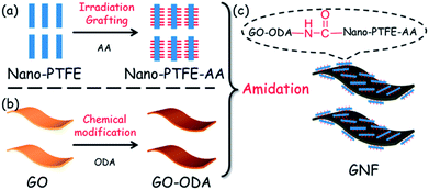
The schematic procedure for preparation of GNF is depicted in Fig. 1. The process includes (a) irradiation grafting of nano-PTFE with AA, yielding nano-PTFE–AA; (b) chemical modification of GO with ODA, yielding GO–ODA, and (c) preparation of GNF by amidation reaction between GO–ODA and nano-PTFE–AA. In the final step, different reaction molar ratios (1![[thin space (1/6-em)]](https://www.rsc.org/images/entities/char_2009.gif) :
:![[thin space (1/6-em)]](https://www.rsc.org/images/entities/char_2009.gif) 1, 1
1, 1![[thin space (1/6-em)]](https://www.rsc.org/images/entities/char_2009.gif) :
:![[thin space (1/6-em)]](https://www.rsc.org/images/entities/char_2009.gif) 2, 1
2, 1![[thin space (1/6-em)]](https://www.rsc.org/images/entities/char_2009.gif) :
:![[thin space (1/6-em)]](https://www.rsc.org/images/entities/char_2009.gif) 5, 1
5, 1![[thin space (1/6-em)]](https://www.rsc.org/images/entities/char_2009.gif) :
:![[thin space (1/6-em)]](https://www.rsc.org/images/entities/char_2009.gif) 10 and 1
10 and 1![[thin space (1/6-em)]](https://www.rsc.org/images/entities/char_2009.gif) :
:![[thin space (1/6-em)]](https://www.rsc.org/images/entities/char_2009.gif) 20) between GO–ODA and nano-PTFE–AA were employed here. The F content of the resulting GNF is a significant parameter to optimize the reaction molar ratio.
20) between GO–ODA and nano-PTFE–AA were employed here. The F content of the resulting GNF is a significant parameter to optimize the reaction molar ratio.
To detect the F content, the as-prepared GNF was analyzed by XPS. As shown in Fig. 2a, the F content of the resulting GNF increases with increasing reaction molar ratio. As demonstrated in the above section (Section 2.2), the as-prepared GNF is free of unreacted materials (nano-PTFE–AA and GO–ODA), excluding physical absorption. Thus, the increasing F content indicates that nano-PTFE–AA has been grafted on the GNF surface. Due to irradiation grafting, the incorporation of nano-PTFE–AA will not cause poor interfacial adhesion. The evidence will be shown in the following section (Section 3.3). As seen, the reaction molar ratio of 1![[thin space (1/6-em)]](https://www.rsc.org/images/entities/char_2009.gif) :
:![[thin space (1/6-em)]](https://www.rsc.org/images/entities/char_2009.gif) 10 yielded optimal reaction efficiency and was selected for further investigations. It is calculated that the as-prepared GNF contain ∼26.3% nano-PTFE–AA.
10 yielded optimal reaction efficiency and was selected for further investigations. It is calculated that the as-prepared GNF contain ∼26.3% nano-PTFE–AA.
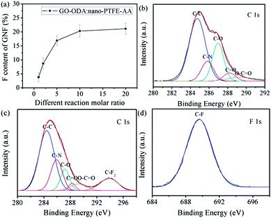 | ||
| Fig. 2 (a) Relationship of F content of GNF with different reaction molar ratio. C 1s XPS spectra of (b) GO–ODA and (c) GNF, and F 1s XPS spectrum of (d) GNF. | ||
The C/O ratio of GO (Fig. S3†) is 1.98, consistent with previous reports (1.8–2.3).40,41 This ratio provides sufficient oxygen functional groups for surface tailoring. After the incorporation of ODA, a new peak assigned to C–N appears, while the C–O and O–C![[double bond, length as m-dash]](https://www.rsc.org/images/entities/char_e001.gif) O peaks are notably suppressed (Fig. 2b).42 This suppression is attributed to the reaction between one amino group of ODA and oxygen functional groups of GO. As demonstrated in previous work,22 the incorporation of excess ODA can keep the other amino group reactive. The same strategy was adopted here, maintaining the other amino group on the GO–ODA surface for further reaction. The XPS spectral comparison of nano-PTFE and nano-PTFE–AA is included (Fig. S4†), and the new peaks assigned to O–C
O peaks are notably suppressed (Fig. 2b).42 This suppression is attributed to the reaction between one amino group of ODA and oxygen functional groups of GO. As demonstrated in previous work,22 the incorporation of excess ODA can keep the other amino group reactive. The same strategy was adopted here, maintaining the other amino group on the GO–ODA surface for further reaction. The XPS spectral comparison of nano-PTFE and nano-PTFE–AA is included (Fig. S4†), and the new peaks assigned to O–C![[double bond, length as m-dash]](https://www.rsc.org/images/entities/char_e001.gif) O appeared in the spectrum of nano-PTFE–AA.43 This indicated that carboxyl groups were grafted onto the nano-PTFE surface.
O appeared in the spectrum of nano-PTFE–AA.43 This indicated that carboxyl groups were grafted onto the nano-PTFE surface.
Evidence for covalent grafting of nano-PTFE–AA onto the GO–ODA surface is provided by XPS spectral comparison between GO–ODA and GNF, as shown in Fig. 2b–d. Compared with GO–ODA, the C–N and O–C![[double bond, length as m-dash]](https://www.rsc.org/images/entities/char_e001.gif) O peaks intensify in the fitting curve of GNF (Fig. 2c), confirming covalent compounding between nano-PTFE–AA and GO–ODA. Furthermore, a new peak assigned to C–F2 appears in the fitting curve of GNF (Fig. 2c and d).43 As demonstrated in the above section (Section 2.2), the as-prepared GNF was free of absorbed nano-PTFE–AA. Consequently, it is concluded that the covalent immobilization of nano-PTFE–AA onto the GNF surface has been achieved. In addition, the carboxyl groups remain in the fitting curve of GNF, which indirectly demonstrates that tethers and restacks between GNF are nearly nonexistent. Note that a certain amount of carboxyl groups on the surface of GNF can provide a feasible platform for achieving homogeneous dispersion of filler and designing strong interface interactions in the matrix.22,44
O peaks intensify in the fitting curve of GNF (Fig. 2c), confirming covalent compounding between nano-PTFE–AA and GO–ODA. Furthermore, a new peak assigned to C–F2 appears in the fitting curve of GNF (Fig. 2c and d).43 As demonstrated in the above section (Section 2.2), the as-prepared GNF was free of absorbed nano-PTFE–AA. Consequently, it is concluded that the covalent immobilization of nano-PTFE–AA onto the GNF surface has been achieved. In addition, the carboxyl groups remain in the fitting curve of GNF, which indirectly demonstrates that tethers and restacks between GNF are nearly nonexistent. Note that a certain amount of carboxyl groups on the surface of GNF can provide a feasible platform for achieving homogeneous dispersion of filler and designing strong interface interactions in the matrix.22,44
A series of FTIR spectral comparisons further confirm the successful preparation of GNF. Regarding irradiation grafting of nano-PTFE, new absorptions arise in the spectrum of the as-prepared nano-PTFE–AA (Fig. S5a†). In particular, the doublet at 2925 and 2830 cm−1 belongs to the C–H stretching vibration of methylene groups from AA, and the appearance of the characteristic band at 1650 cm−1 (C![[double bond, length as m-dash]](https://www.rsc.org/images/entities/char_e001.gif) O stretching vibration from carboxyl groups) provides further evidence. Regarding chemical modification of GO, GO–ODA spectrum shows new bands (Fig. S5b†) at 1500 cm−1 (C–C stretching vibration from benzene ring) and 1226 cm−1 (C–O–C stretching vibration from ether linkage), indicating that ODA has been covalently grafted onto the GO surface. Moreover, the band at 1060 cm−1 (C–O–C in epoxide groups) disappears,44 while the bands at 1105 cm−1 (C–N bending vibration), 3300 cm−1 (N–H stretching vibration) and 1545 cm−1 (N–H bending vibration) appear in the spectrum of GO–ODA.22,36 These changes demonstrate that amino groups of ODA have reacted with oxygen functional groups of GO.
O stretching vibration from carboxyl groups) provides further evidence. Regarding chemical modification of GO, GO–ODA spectrum shows new bands (Fig. S5b†) at 1500 cm−1 (C–C stretching vibration from benzene ring) and 1226 cm−1 (C–O–C stretching vibration from ether linkage), indicating that ODA has been covalently grafted onto the GO surface. Moreover, the band at 1060 cm−1 (C–O–C in epoxide groups) disappears,44 while the bands at 1105 cm−1 (C–N bending vibration), 3300 cm−1 (N–H stretching vibration) and 1545 cm−1 (N–H bending vibration) appear in the spectrum of GO–ODA.22,36 These changes demonstrate that amino groups of ODA have reacted with oxygen functional groups of GO.
In comparison with GO–ODA and nano-PTFE–AA, the doublet at 1213 and 1238 cm−1 (C–F stretching vibration from nano-PTFE–AA), and another one at 2925 and 2830 cm−1 (C–H stretching vibration from GO–ODA) appear in the spectrum of GNF (Fig. 3a). Furthermore, the bands at 1105 cm−1 (C–N bending vibration) and 1545 cm−1 (N–H bending vibration of amide) intensify. These features verify that nano-PTFE–AA has been covalently immobilized on the GNF surface by amide linkage. Note that the shoulder peak at 1715 cm−1, assigned to carboxyl groups, persists in the spectrum of GNF, which is consistent with of XRS results. Furthermore, the bands at 639, 625, 556, 505 cm−1 appear in the spectra of nano-PTFE–AA and GNF, indicating that the immobilized nano-PTFE–AA is also composed of crystalline slices.45 This special laminar structure is critical to low friction coefficient.
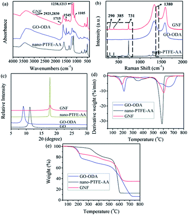 | ||
| Fig. 3 (a) FTIR spectra, (b) Raman spectra (excitation wavelength 631 nm), (c) XRD patterns, (d) DTG curves and (e) TGA thermograms of nano-PTFE–AA, GO–ODA and GNF. | ||
Structural features of GNF also have been identified using Raman spectroscopy. Fig. 3b shows the Raman spectra of nano-PTFE–AA, GO–ODA and GNF. The characteristic peaks at 290, 385, 731, 1380 cm−1 are ascribed to crystalline slices. These peaks appear in the spectra of both nano-PTFE–AA and GNF.46 This further confirms the immobilization of nano-PTFE–AA onto the GNF surface.
The detailed structure of GNF and the near-absence of stacking order for GNF were manifested in XRD patterns, as demonstrated in Fig. 3c. The XRD pattern for GO exhibits a strong peak at 11.14°, corresponding to an interlayer spacing of ∼0.79 nm while GO–ODA exhibits a peak at 9.07°, corresponding to an increased interlayer spacing of ∼0.96 nm. The patterns provide a supporting evidence for the attachment of ODA onto the GO surface.47 After the incorporation of nano-PTFE–AA, the XRD pattern of GNF exhibits no visible peak except for a weak and broad diffraction peak at 17.8° that is ascribed to crystalline slices of nano-PTFE–AA on the GNF surface. This peak provides definitive evidence for the immobilization. In addition, no other visible peak is present in the pattern from as-prepared GNF, suggesting that the remaining stacking is disordered.22,37
Results of TGA measurements are presented in Fig. 3d and e. Two major mass loss peaks of GNF can be observed from the derivative TG (DTG) plot. The first mass loss peak, which appears at approximately 200 °C, results from the decomposition of GO–ODA, while the second peak at 605 °C arises primarily from pyrolysis of nano-PTFE–AA. This further illustrates that nano-PTFE–AA has been immobilized onto the GNF surface. After nano-PTFE–AA grafting, the thermal stability and carbon residue rate of as-prepared GNF are enhanced, indicating that the new chemical bonds have greater thermal stability.48 The immobilized nano-PTFE–AA can act as effective barriers to resist the decomposition of oxygen functionalized groups on the GNF.36 Consequently, this can delay thermal degradation at high temperature, and increase the service temperature of the matrix.
Achieving uniform dispersion of nano-PTFE within the matrix and avoiding irreversible agglomerates present a major challenge.29,30 Fortunately, previous literatures reveal that various functionalized graphene can be stably suspended in DMF solvent.11,22,36 The dispersibility and stability of GNF was tested directly in DMF solvent (Fig. S6†). Though the nano-PTFE was irradiated with AA, the AA-rich surface was not sufficient to achieve a stable dispersion. However, the GNF suspension was stable and homogeneous even after two days (Fig. S6b†). We assert that functionalized graphene acts as a leaf-like platform to suspend immobilized nano-PTFE–AA in DMF solvent.
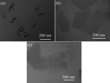
To further illustrate the complete exfoliation and stable dispersion of GNF in the DMF solvent, TEM images of GNF were acquired after the GNF dispersion was maintained for two days. For comparison, TEM images of as-prepared nano-PTFE–AA and GO–ODA dispersions were also recorded immediately. As shown in Fig. 4a and b, the nano-PTFE–AA has an average width and length of 20 and 90 nm, and GO–ODA platelets are transparent and quite large, even after surface modification. This suggests that GO–ODA affords an effective platform for the immobilization of nano-PTFE–AA.
TEM images showed negligible restacking of GNF (Fig. 4c), consistent with XRD results. This disruption of the structure reduces attractive interactions between GNF sheets, facilitating exfoliation into individual sheets.47 Moreover, nano-PTFE–AA particles are homogeneously distributed on the GNF surface. As suggested by Zhang and co-workers,49 the nano-PTFE–AA grafted onto the GNF surface can serve as a geometric impediment to the restacking of exfoliated GNF sheets. The absence of obvious agglomerations of nano-PTFE–AA and GO–ODA contributes to synergy effect and produces a homogeneous dispersion in the matrix. The synergy effect between nano-PTFE and GO will be discussed in the Fig. 7. In addition, despite the high degree of coverage of nano-PTFE–AA on the GNF surface, the GNF remains flat and without obvious wrinkles, which will enhance the retention of physical properties.18
3.2 Tribological properties of GNF/polymer composites
GNF derives the attributes of low friction coefficient from nano-PTFE and high wear resistance from GO, and thus appears to be a viable self-lubricating and anti-wear filler for polymer composites. To investigate tribological effectiveness of GNF addition, both PI and EP were employed as host matrices. The appropriate friction condition was chosen, according to our previous work.22,37,50 Friction tests were conducted on as-prepared specimens using a reciprocating friction and wear testing machine, yielding values for friction coefficient and wear rate.Fig. 5a and b illustrate friction coefficient values for GNF/PI and GNF/EP specimens as a function of sliding time. The incorporation of GNF significantly reduces friction coefficient of GNF/polymer composites. Furthermore, the fluctuation phenomenon in the friction coefficient curves diminishes with GNF addition. For GNF/PI composites, when GNF content reaches 0.1 wt%, the run-in period is reduced to about half a minute (Fig. 5a). For GNF/EP composites, when GNF content reaches 0.5 wt%, the run-in period is limited to three minutes (Fig. 5b). The reduction in the run-in period indicates that GNF addition has significant self-lubricating effect on friction coefficient. When the sliding time is over five minutes, the friction coefficient of the 0.1GNF/PI and 0.2GNF/PI specimens gradually increases, indicating that the self-lubricating effect is diminishing. However, the friction coefficient value is still much lower than that of neat PI.
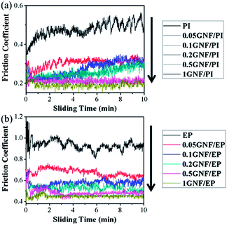 | ||
| Fig. 5 Friction coefficient values for the (a) GNF/PI and (b) GNF/EP specimens as a function of sliding time. (Reciprocating frequency: 10 Hz, sliding distance: 480 m, load: 10 N, RH: 40%.) | ||
Average friction coefficient values were extracted from the plots of friction coefficient as a function of sliding time, and changes in friction coefficient with GNF content are shown in Fig. S7a and b.† As expected, the reduction in friction coefficient in the 1GNF/PI and 1GNF/EP specimens is 59% and 51%, respectively. In previous work,22 with 2 wt% modified graphene addition, only 12% reduction was obtained in friction coefficient. In addition, the friction coefficient of GO/EP composites increased by >100% with 0.1 wt% GO addition.37 The distinctly different tribological behavior illustrates the self-lubricating effect of GNF. Though the friction coefficient values for both GNF/PI and GNF/EP show a similar downtrend with increasing GNF content, the dependence saturates at different loadings (0.5 wt% for PI and 0.2 wt% for EP). Note that the self-lubricating effect saturates when the reduction in friction coefficient reaches ∼50%.
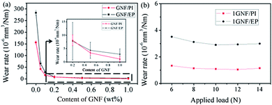
Fig. 6a shows the relationship of wear rate of GNF/PI and GNF/EP specimens with different GNF content. The wear rates decrease nearly two orders of magnitude in both GNF/PI and GNF/EP specimens with only 0.5 wt% GNF addition, illustrating the anti-wear effect of GNF addition. However, in our previous work,22 with 2 wt% modified graphene addition, only one order of magnitude was obtained in wear rate. Likewise, as reported by Shen and co-workers,27 the incorporation of 0.5 wt% GO into an EP matrix also provided only one order of magnitude reduction in wear rate. Compared to these reports that there is few reduction in friction coefficient, the reduction in friction coefficient is about 50% in GNF/PI and GNF/EP specimens with 1 wt% GNF addition, and this further improve wear resistance.
In order to investigate wear resistance of GNF/polymer specimens under different applied load, 1GNF/PI and 1GNF/EP specimens were chosen here, and the load was selected from 6 to 14 N (from low to high), according to previous literatures.22,37,50 Fig. 6b shows the relationship of wear rate of 1GNF/PI and 1GNF/EP specimens with different applied load. Both GNF/PI and GNF/EP specimens can still keep relatively low wear rate even though the applied load is increased to 14 N. However, previous literature reported that polyimide composite reinforced with 2 wt% modified graphene has higher wear rate (0.66 × 10⁻⁵ mm3 N m−1) even though the applied load is only 6 N.22 This comparison indicates that GNF/polymer specimens also can keep superior wear resistance even under higher load.
As well known, bulk graphite (a source of graphene) has the best performance in humid environments but fails to deliver low friction coefficient and wear in dry environment.20 Thus, the different RH values are chosen to further study the corresponding tribological properties. As shown in Fig. S8a and b,† it is found that there are similar tribological properties for GNF/PI and GNF/EP specimens under various RH conditions. Because nano-PTFE was immobilized onto the GNF surface, this may be beneficial for keeping stable performance against RH values change.
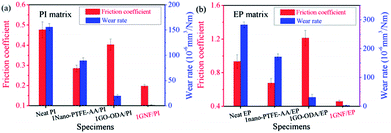
Fig. 7 shows comparisons tribological properties of neat PI, 1nano-PTFE–AA/PI, 1GO–ODA/PI and 1GNF/PI specimens, and of neat EP, 1nano-PTFE–AA/EP, 1GO–ODA/EP and 1GNF/EP specimens. GNF addition affords the lowest values both in friction coefficient and wear rate of polymer composites. The detailed data for friction coefficient and wear rate is included in Table S1.† For example, the reduction in friction coefficient is only about 40.2% for 1nano-PTFE–AA/PI specimen, and is about 27.5% for 1nano-PTFE–AA/EP specimen. The reduction in wear rate is roughly an order of magnitude for 1GO–ODA/PI and 1GO–ODA/EP specimens, however, the friction coefficient of 1GO–ODA/EP specimen increases by 29.9%, compared to neat EP. The large differences in tribological properties of the GNF/polymer composites and the control samples demonstrate the synergy effect achieved by GNF addition as a self-lubricating and anti-wear nano-solid lubricant.
3.3 Tribological mechanism of GNF/polymer composites
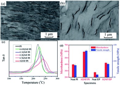
As shown above, GNF addition can significantly improve tribological properties of common engineering polymers. As described by Ratner–Lancaster,37,51 tribological behaviour of polymer composites is subjected to numerous factors, including dispersion of filler, interfacial adhesion, transfer film, mechanical properties, hardness, processing technology, softening point and so on. Thus, tribological mechanism of GNF/polymer can be acquired from two stages: before and after tribological experiment.Before tribological experiment, filler dispersion and interface determine filler effectiveness in light of filling modification. As a simple qualitative test, GNF/PI and GNF/EP specimens were examined visually (Fig. S9,† dog-bone type for mechanical tests), revealing a homogeneous dispersion of GNF in the matrix. As shown in Fig. 8a and b, TEM images of GNF/PI and GNF/EP show GNF embedded into the polymers without cracks or agglomerations, demonstrating that the stable and uniform suspension of GNF allows homogenous incorporation into polymer matrices. Furthermore, it seems that GNF dispersion is oriented. In other words, this is a preorientation of GNF, which contributes to efficient stress transfer throughout the materials.22 As demonstrated above, there are a certain amount of carboxyl groups on the surface of GNF. The reactive carboxyl groups of GNF can react with precursors of PI and EP via in situ polymerization, affording covalent bonding between two phases.22,27,42 To explore the interface of GNF/polymer composites, GNF/PI composites were chosen here as a representative for study, due to the same mechanism. As shown in Fig. 8c, it is found that segment confinement/restriction increase with increasing GNF addition, due to immobilization of polymer chains near the GNF surface.22 As a result, glass transition temperature (Tg) value increases with increasing GNF addition. This is ascribed to strong covalent adhesion between two phases. Furthermore, the immobilized nano-PTFE provides a micro-rough GNF surface (Fig. 4c) that mechanically interlocks with the polymer matrices. This also contributes to the confinement effect at interfaces. The two factors (covalent adhesion and mechanical interlock) provide strong interface between two phases. Note that the homogenous and oriented dispersion and excellent interfacial adhesion facilitate stress transfer across interfaces, ensuring superior effectiveness of GNF.52–54 This enhances mechanical performance and reduces failure elements during friction tests, yielding high wear resistance.
As known, better mechanical properties contribute to better wear resistance. As shown in Fig. 8d, with 1 wt% GNF addition, the microhardness of GNF/PI and GNF/EP composites increased by 49.5% and 52.7%, respectively. Furthermore, the increase in tensile strength of 1GNF/PI and 1GNF/EP composites is 51.7% and 56.9%, respectively. The detailed data for mechanical properties of other specimens was detected in Table S2.† According to these mechanical and tribological properties, it is believed that the increase in microhardness enhances the bearing capacity of specimens against applied load, further enhancing tribological properties.22,37,55 In addition, the increased tensile strength of specimens also leads to better resistance to exfoliation during friction process.51,56
After tribological experiment, SEM observations of worn surfaces and wear debris can provide insight into the mechanism (Fig. 9). For worn surface aspect, the reduction in wear width is consistent with wear rate shown in Fig. 9a–d. As shown in Fig. 9a and b, the wear width for 1GNF/PI is much narrower (0.16 mm) than for neat PI (0.84 mm), and the worn surface of neat PI exhibits deep furrows and large cracks (marked by red ellipses). In contrast, the worn surface of 1GNF/PI is relatively flat and smooth, reflecting a reduction in abrasive and fatigue wear. For the second composite (GNF/EP), the wear width decreases from 1.02 to 0.23 mm with only 1 wt% GNF addition (Fig. 9c and d). The worn surface of neat EP presents small ridges, while that of 1GNF/EP is much smoother. For wear debris aspect, with 1 wt% GNF addition, the morphology of wear debris is changed from large sheet to small particle for GNF/PI and GNF/EP specimens.
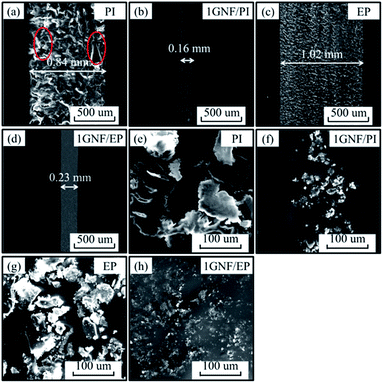 | ||
| Fig. 9 SEM images of worn surfaces and wear debris of (a and e) neat PI, (b and f) 1GNF/PI, (c and g) neat EP and (d and h) 1GNF/EP specimens. | ||
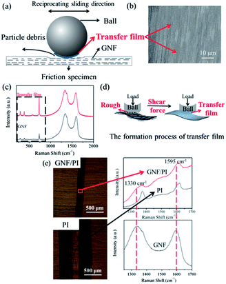
To present clearly, the schematic diagram in Fig. 10a shows tribological mechanism of GNF/polymer composites. The PI matrix is chosen to illustrate the self-lubricating and anti-wear effects of GNF addition, due to the same tribological mechanism. For friction coefficient aspect, as shown in Fig. 10b, there is a homogeneous and even self-lubricating transfer film on the counterpart, according to SEM observation. To further explore the transfer film, Raman analysis was utilized to study its component. Raman spectrum of transfer film reveals the characteristic peaks of GNF, as shown in Fig. 10c. Furthermore, characteristic peaks assigned to nano-PTFE greatly increase while those assigned to GO–ODA remain unchanged. In addition, there is homogenous F dispersion (Fig. S10†) arises on the counterpart. These indicate that the transfer film is mainly composed of nano-PTFE. According to Tanaka et al. nano-PTFE has low activation energy for crystalline slices slippage (7 kcal mol−1),28 which contributes to the formation of transfer film, providing a low friction coefficient. Thus the formation of transfer film (Fig. 10d) can be explained, as follows: under shear force, the immobilized nano-PTFE on the GNF surface forms a self-lubricating transfer film on the counterpart, due to the peculiar structure of crystalline slices.28 The transfer film at the sliding interface between counterpart and specimens greatly reduces direct contact and scraping, effectively reducing abrasive wear on the worn surface (Fig. 9b and d).18 The corresponding friction force was also reduced, yielding a low friction coefficient. Similarly, Wang et al. also reported that the significant reduction in friction coefficient of GNF/polymer specimens could be ascribed to the transfer film on the counterpart surface.30
For wear resistance aspect, GNF has protective effect. It is found in Fig. 10e that there is GNF layer on the worn surface by Raman spectral comparison between GNF/PI and PI even after ultrasonic washing. Thus, the high specific surface area and the two-dimensional planar geometry of GNF on the worn surface (Fig. 10a) also absorb the energy generated by compression and shear during friction process. This GNF layer provides effective protection against the forces associated with sliding, thus contributing to the increased wear resistance. In addition, GNF also has suppression effect. When the ball does reciprocating sliding, the large interfacial contact makes GNF interfere with and suppress the generation of wear debris on the worn surface. As a result, the morphology of wear debris (Fig. 9e–h) is transformed from large-sheet to small-particle. Therefore, the tribological effect (protective effect and suppression effect) of GNF can effectively enhance wear resistance of specimens. Furthermore, Due to the large reduction in friction force, the corresponding reductions in damage area and frictional heat are beneficial to improve wear resistance.
Based on the above discussion, the self-lubricating and anti-wear effects of GNF addition produced low friction coefficient and high wear resistance. The improved tribological properties are ascribed to four aspects: homogeneous and oriented GNF dispersion and strong interface, the enhanced mechanical properties, transfer film and tribological effect of GNF. Furthermore, the homogeneous and oriented dispersion and strong interface strengthen the other three aspects to further improve tribological properties.
4. Conclusions
In this work, GNF was prepared by a feasible approach, combining two intrinsic functions between GO and nano-PTFE to achieve a self-lubricating and anti-wear additive. The 1 wt% GNF addition resulted in a nearly 60% reduction in friction coefficient and more than two orders of magnitude reduction in wear rate for both GNF/PI and GNF/EP composites. Furthermore, the synergy effect of nano-PTFE and GO was achieved both in the PI and EP matrices. The considerable increase in tribological properties is ascribed to four aspects: homogeneous GNF dispersion and strong interface, the enhanced mechanical properties, transfer film and tribological effect of GNF, especially the introduction of transfer film resolved high friction coefficient to further improve wear resistance. GNF is a potentially superior self-lubricating and anti-wear nano-solid lubricant that minimizes wear. Deployed in engineering polymers, the additive can increase energy efficiency, and eliminate lubricating oil pollution to contribute to environmental cleanliness.Acknowledgements
This work was financially supported by Fudan University and National Basic Research Program of China (2011CB605704). X. C. Li and M. S. Wu are thanked for their helpful comments.Notes and references
- R. I. Taylor, Faraday Discuss., 2012, 156, 361–382 RSC.
- R. Gusain and O. P. Khatri, J. Mater. Chem. A, 2013, 1, 5612–5619 CAS.
- F. Zhou, Y. M. Liang and W. M. Liu, Chem. Soc. Rev., 2009, 38, 2590–2599 RSC.
- X. F. Zhang, B. Luster, A. Church, C. Muratore, A. A. Voevodin and P. Kohli, ACS Appl. Mater. Interfaces, 2009, 1, 735–739 CAS.
- H. Xu, Y. J. Wang, H. F. Li, L. Liu, F. Deng and G. X. Chen, J. Mater. Chem., 2009, 19, 6896–6900 RSC.
- Y. L. Hsin, H. Y. Chu, Y. R. Jeng, Y. H. Huang, M. H. Wang and C. K. Chang, J. Mater. Chem., 2011, 21, 13213–13222 RSC.
- N. D. Spencer, Faraday Discuss., 2012, 156, 435–438 RSC.
- P. Samyn, D. E. P. Baets, G. Schoukens and B. Hendrickx, Polym. Eng. Sci., 2003, 43, 1477–1487 CAS.
- Y. J. Shi, L. W. Mu, X. Feng and X. H. Lu, J. Appl. Polym. Sci., 2011, 121, 1574–1578 CrossRef CAS.
- P. Samyn and G. Schoukens, Polym. Compos., 2009, 30, 1631–1646 CrossRef CAS.
- M. Song and D. Y. Cai, in Polymer-graphene nanocomposites: Graphene Functionalization: A Review, ed. V. Mittal, Royal Society of Chemistry, London, 2012, pp. 1–52 Search PubMed.
- C. G. Lee, Q. Y. Li, W. Kalb, X. Z. Liu, H. Berger and R. W. Carpick, Science, 2010, 328, 76–80 CrossRef CAS PubMed.
- K. S. Kim, H. J. Lee, C. G. Lee, S. K. Lee, H. Jang and J. H. Ahn, ACS Nano, 2011, 5, 5107–5114 CrossRef CAS PubMed.
- Y. J. Shin, R. Stromberg, R. Nay, H. Huang, A. T. S. Wee and H. Yang, Carbon, 2011, 49, 4059–4073 CrossRef PubMed.
- V. Eswaraiah, V. Sankaranarayanan and S. Ramaprabhu, ACS Appl. Mater. Interfaces, 2011, 3, 4221–4227 CAS.
- Y. J. Mi, Z. F. Wang, X. H. Liu, S. R. Yang, H. G. Wang and J. F. Ou, J. Mater. Chem., 2012, 22, 8036–8042 RSC.
- S. Choudhary, H. P. Mungse and O. P. Khatri, J. Mater. Chem., 2012, 22, 21032–21039 RSC.
- H. J. Song, X. H. Jia, N. Li, X. F. Yang and H. Tang, J. Mater. Chem., 2012, 22, 895–902 RSC.
- D. Berman, A. Erdemir and A. V. Sumant, Carbon, 2013, 54, 454–459 CrossRef CAS PubMed.
- D. Berman, A. Erdemir and A. V. Sumant, Carbon, 2013, 59, 167–175 CrossRef CAS PubMed.
- S. S. Kandanur, M. A. Rafiee, F. Yavari, M. Schrameyer, Z. Z. Yu and T. A. Blanchet, Carbon, 2012, 50, 3178–3183 CrossRef CAS PubMed.
- T. Huang, Y. S. Xin, T. S. Li, S. Nutt, C. Su and H. M. Chen, ACS Appl. Mater. Interfaces, 2013, 5, 4878–4891 CAS.
- Z. X. Tai, Y. F. Chen, Y. F. An, X. B. Yan and Q. J. Xue, Tribol. Lett., 2012, 46, 55–63 CrossRef CAS PubMed.
- Y. F. An, Z. X. Tai, Y. Y. Qi, X. B. Yan, B. Liu, Q. J. Xue and J. Y. Pei, J. Appl. Polym. Sci., 2014, 131, 39640 Search PubMed.
- B. L. Pan, G. Q. Xu, B. Zhang, X. J. Ma, H. Z. Li and Y. Z. Zhang, Polym.-Plast. Technol. Eng., 2012, 51, 1163–1166 CrossRef CAS.
- H. J. Song, N. Li, Y. J. Li, C. Y. Min and Z. Wang, J. Mater. Sci., 2012, 47, 6436–6443 CrossRef CAS PubMed.
- X. J. Shen, X. Q. Pei, S. Y. Fu and K. Friedrich, Polymer, 2013, 54, 1234–1242 CrossRef CAS PubMed.
- K. Tanaka, Y. Uchiyama and S. Toyooka, Wear, 1973, 23, 153–172 CrossRef CAS.
- M. Sharma and J. Bijwe, J. Mater. Sci., 2012, 47, 4928–4935 CrossRef CAS.
- H. Y. Wang, R. G. Lu, T. Huang, Y. N. Ma, P. H. Cong and T. S. Li, Mater. Sci. Eng., A, 2011, 528, 6878–6886 CrossRef CAS PubMed.
- T. Huang, R. G. Lu, H. Y. Wang, Y. N. Ma, J. S. Tian and T. S. Li, J. Macromol. Sci., Part B: Phys., 2011, 50, 1235–1248 CrossRef CAS.
- C. Zhang, S. Huang, W. W. Tjiu, W. Fan and T. X. Liu, J. Mater. Chem., 2012, 22, 2427–2434 RSC.
- L. J. Brennan, S. T. Barwich, A. Satti, A. Faure and Y. K. Gun'ko, J. Mater. Chem. A, 2013, 1, 8379–8384 CAS.
- Q. Tang, Z. Zhou and Z. F. Chen, Nanoscale, 2013, 5, 4541–4583 RSC.
- Y. G. Li, H. L. Wang, L. M. Xie, Y. Y. Liang, G. S. Hong and H. J. Dai, J. Am. Chem. Soc., 2011, 133, 7296–7299 CrossRef CAS PubMed.
- T. Huang, R. G. Lu, C. Su, H. N. Wang, Z. Guo and P. Liu, ACS Appl. Mater. Interfaces, 2012, 4, 2699–2708 CAS.
- T. Huang, P. Liu, R. G. Lu, Z. Y. Huang, H. M. Chen and T. S. Li, Wear, 2012, 292–293, 25–32 CrossRef CAS PubMed.
- W. C. Oliver and G. M. Pharr, J. Mater. Res., 1992, 7, 1564–1583 CrossRef CAS.
- W. C. Oliver and G. M. Pharr, J. Mater. Res., 2004, 19, 3–19 CrossRef CAS.
- Z. X. Chen and H. B. Lu, J. Mater. Chem., 2012, 22, 12479–12490 RSC.
- R. S. Edwards and K. S. Coleman, Nanoscale, 2013, 5, 38–51 RSC.
- W. J. Li, X. Z. Tang, H. B. Zhang, Z. G. Jiang, Z. Z. Yu, X. S. Du and Y. W. Mai, Carbon, 2011, 49, 4724–4730 CrossRef CAS PubMed.
- C. Wang and J. R. Chen, Appl. Surf. Sci., 2007, 253, 4599–4606 CrossRef CAS PubMed.
- G. Y. Kim, M. C. Choi, D. Lee and C. S. Ha, Macromol. Mater. Eng., 2012, 297, 303–311 CrossRef CAS.
- M. Kobayashi, M. Sakashita and T. Adachi, Macromolecules, 1995, 28, 316–324 CrossRef CAS.
- F. J. Boerio and J. L. Koenig, J. Chem. Phys., 1971, 54, 3557–3559 CrossRef PubMed.
- Y. W. Cao, Z. L. Lai, J. C. Feng and P. Y. Wu, J. Mater. Chem., 2011, 21, 9271–9278 RSC.
- X. Y. Zhang, Y. Huang, Y. Wang, Y. F. Ma, Z. F. Liu and Y. S. Chen, Carbon, 2008, 47, 313–347 Search PubMed.
- Y. Zhang, L. Q. Ren, S. R. Wang, A. Marathe, J. Chaudhuri and G. Li, J. Mater. Chem., 2011, 21, 5386–5391 RSC.
- S. Q Lai, Y. Li, T. S. Li, X. J. Liu and R. G. Lv, Macromol. Mater. Eng., 2005, 290, 195–201 CrossRef.
- I. M. Hutchings, in Tribology: Friction and Wear of Engineering Materials, Elsevier Limited, London, 1992 Search PubMed.
- R. J. Young, L. A. Kinloch, L. Gong and K. S. Novoselov, Compos. Sci. Technol., 2012, 72, 1459–1476 CrossRef CAS PubMed.
- M. A. Rafiee, J. Rafiee, Z. Wang, H. H. Song, Z. Z. Yu and N. Koratkar, ACS Nano, 2009, 3, 3884–3890 CrossRef CAS PubMed.
- M. A. Rafiee, W. Lu, A. V. Thomas, A. Zandiatashbar, J. Rafiee and J. M. Tour, ACS Nano, 2010, 4, 7415–7420 CrossRef CAS PubMed.
- N. Satyanarayana, K. S. S. Rajan, S. K. Sinha and L. Shen, Tribol. Lett., 2007, 27, 181–188 CrossRef CAS.
- G. W. Stachowiak and A. W. Batchelor, Engineering Tribology, Elsevier Butter-worth-Heinemann, Amsterdam, Netherlands, 2005 Search PubMed.
Footnote |
| † Electronic supplementary information (ESI) available: Contact configuration of the reciprocating friction and wear testing machine; FTIR spectra of last filtrate, FTIR and XPS spectra of as-prepared products; dispersibility of nano-PTFE–AA, and GO–ODA, GNF; relationship of average friction coefficient values for the GNF/polymer specimens with GNF content; tribological properties of 1GNF/polymer specimens under various RH conditions; appearance for dog-bone type specimens; EDX elemental mapping of F dispersion; tribological properties, microhardness and tensile strength of as-prepared specimens. See DOI: 10.1039/c4ra01964d |
| This journal is © The Royal Society of Chemistry 2014 |

