 Open Access Article
Intrinsically stretchable and rechargeable batteries for self-powered stretchable electronics
Gerald
Kettlgruber
*,
Martin
Kaltenbrunner
,
Christian M.
Siket
,
Richard
Moser
,
Ingrid M.
Graz
,
Reinhard
Schwödiauer
and
Siegfried
Bauer
Soft Matter Physics, Johannes Kepler University Linz, Altenbergerstrasse 69, 4040 Linz, Austria. E-mail: gerald.kettlgruber@jku.at; martin.kaltenbrunner@jku.at; christian.siket@jku.at; richard.moser@jku.at; ingrid.graz@jku.at; reinhard.schwoediauer@jku.at; sbauer@jku.at; Tel: +43 732 2468 1694 Tel: +43 732 2468 9256 Tel: +43 732 2468 9241
First published on 7th March 2013
Abstract
Stretchable electronic circuits conform to irregular three dimensional surfaces. They are formed with soft materials and contain electronic circuits, sensors, and other components. We report on a soft matter based rechargeable electrochemical power storage element for such devices. The chemistry is based on a rechargeable alkaline manganese battery concept. The cells withstand more than 700 mechanical stretch relaxation cycles up to 25% strain, with an average cell capacity of 6.5 mA h. Combined with wireless power transmission or stretchable solar cells, the rechargeable battery can be used to store and supply energy in stretchable electronic devices.
Introduction
Artificial electronic muscles, electronic skin, and electronic bio-interfaces can be stretched by mechanical and electrical forces. Such devices conform to non-developable surfaces that cannot be shaped by the simple bending of a sheet, and thus support applications in, for example, mobile electronic appliances, the moving parts of robots, textiles, and health care.1–5 In addition to designing optical6 and braille7 displays, passive1,8 and active electronic circuit elements,2–5 and sensors,9–12 it is also essential to develop suitable means for power supply, storage, transmission, distribution, and generation. Alongside coils for wireless power transmission,13,14 solar cells,15–18 supercapacitors,19–21 and non-rechargeable batteries,22–24 mechanically compliant power sources are at the frontier of research in stretchable electronics.25Here we extend our previous study of a stretchable electrochemical power source22 to a highly durable, mechanically stable, compliant, rechargeable battery with high energy density: our battery withstands more than 20 full charge–discharge cycles over more than 700 mechanical stretch–relaxation cycles at up to 25% strain. An average cell capacity of 6.5 mA h is achieved when discharging to 1.1 V after the first recharging process. Short-circuit currents of 55 mA initially and over 20 mA after 150 s of operation under short-circuit conditions facilitate the extraction of high power for a considerable amount of time. The nearly stretch independent power density of the battery is 1.925 mW g−1, obtained from current voltage measurements with different external load resistances connected to the battery. Such batteries permit efficient power storage and supply to stand-alone stretchable electronic items and may be recharged wirelessly or by means of stretchable solar cells.
Experimental
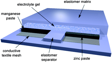
We first describe the preparation of the stretchable accumulator and the equipment used for the mechanical and electrical characterization of the devices.Fig. 1 shows the scheme of our stretchable accumulator. An acrylic elastomer (3M VHB 4910, double sided adhesive transparent, 1 mm thick) forms a compliant matrix in which the chemically active pastes and gels are embedded. The VHB elastomer shows excellent compatibility with the alkaline electrolyte; no softening or decomposition of the elastomer has been observed. Textile fiber meshes with a conductive metal coating act as low-resistivity electrodes to collect the current efficiently.26 The chemically active materials are Zn and MnO2 in an alkaline electrolyte, the basic components of rechargeable alkaline manganese (RAM) cells.27,28 Recently, a stretchable Li-ion cell with non-compliant Li-ion battery islands connected by compliant serpentine electrodes was presented.29 In comparison to this rigid island device, stretchable interconnect approach our intrinsically stretchable battery has the distinct advantage of large area coverage. Active areas of approximately 3 cm2 for the cathode and 1.5 cm2 for the anode are prepared with a lateral separation of 0.5 cm to avoid intermixing of the chemicals upon stretching. The active electrodes are electrically connected with an electrolyte gel.
 | ||
| Fig. 1 Scheme of a rechargeable stretchable alkaline manganese cell. Chemically active pastes and gels are embedded in a compliant elastomer matrix. Conductive textile fiber meshes serve as low-resistivity electrodes to efficiently collect currents. | ||
A structured elastomer with cutaways for the gels and pastes forms the matrix of our stretchable accumulators. A central chamber of 0.5 × 3 cm that contains the zinc anode gel is flanked by two chambers of 1 × 3 cm each for the manganese dioxide cathode paste. Lateral gaps of 0.5 cm separate the chambers to avoid intermixing of the gels. Since the cathode gel requires a larger volume due to its lower density, this design ensures optimal utilization of the MnO2 paste. Diamond-shaped conductive textile meshes with a fiber thickness of 140 μm applied to the bottom of the cutaways act as stretchable, highly conductive electrodes. Silver-coated textile meshes are used for the anode, while an additional layer of 20 μm nickel was deposited by galvanization onto the textile mesh to form the cathode. The dense nickel layer prevents the formation of silver-manganese dioxide microcells that would lead to self-discharge and hydrogen formation. Further deposition of nickel on the mesh resulted in better conductivity but reduced stretchability of the mesh. Optimization may be possible by optimizing the layout of the battery, for example by reducing the elastomer thickness and the amount of passive elastomer surrounding the battery. The alkaline electrolyte (40 wt% KOH in purified water) was gelled by dissolving 7 wt% carboxymethyl cellulose sodium salt (CMC, obtained from FLUKA). The chemically active pastes – an 80% Zn and 20% electrolyte gel paste for the anode, and a 20% MnO2, 6.5% carbon black, and 73.5% electrolyte paste for the cathode (all chemicals measured in weight percent) – were plotted on top of the conductive textile meshes. The zinc powder (obtained from Grillo AG) is optimized for use in commercial alkaline-manganese batteries and contains gallium, bismuth, and indium additives. Finally, the accumulator circuit was closed by plotting a CMC electrolyte gel on and between the electrodes. The accumulator, with a thickness of 2 mm, is sealed with a top layer of the acrylic VHB elastomer. A typical device uses 0.32 g cm−2 of Zn paste, 0.49 g cm−2 of MnO2 paste, and 0.2 g cm−2 of electrolyte gel.
Electrical characterization of the stretchable accumulators was carried out with a Keithley 2400 sourcemeter and a Keithley 2000 multimeter. Stretching experiments were performed on a purpose-built rack controlled by a custom LabView script.
Results and discussion
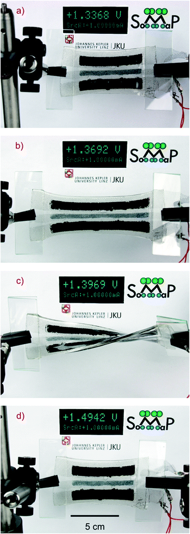
The accumulator described in Fig. 1, while being charged and discharged, can be stretched by up to 75% without any observable change in performance compared to non-stretched cells. From current voltage measurements of the battery we have found that the internal resistance of the battery is load independent.By measuring the open circuit voltage and the short circuit current in different states of stretch up to 75% we have found that the internal resistance of the cell varies by only 5%. Fig. 2a shows an unstretched accumulator being charged with a constant current of 1 mA. In Fig. 2b, the cell is stretched by more than 50% while being charged, as indicated by the increasing terminal voltage on the Keithley voltage and current meter. The extreme compliance of such an accumulator is demonstrated in Fig. 2c, where the cell is simultaneously stretched and twisted by more than 90 degrees while remaining fully operational, as confirmed by the instrument. Fig. 2d shows the accumulator again in the non-stretched state, while charging continues.
 | ||
| Fig. 2 Photos of the accumulator in different stretch states during charging with a constant current of 1 mA. (a) Unstretched accumulator, (b) stretched accumulator to more than 50% strain, (c) simultaneous stretch and twist by more than 90° of the accumulator and (d) return to the unstretched state. | ||
Stretching by 75% resulted in anode and cathode resistances of approximately 20 Ω and 4 Ω per total electrode length respectively. The lower resistivity of the nickel-coated cathode helps to collect the current more efficiently, while the higher resistivity of the silver-coated anode electrode material does not influence device performance, since the highly conductive zinc particles form a percolation path even at high stretch values.
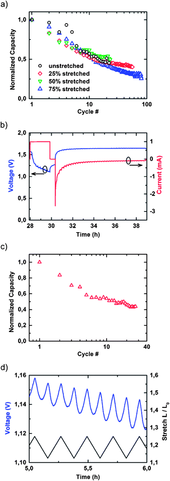
Fig. 3a shows the normalized cell capacitances for an unstretched battery and for batteries stretched to 25%, 50%, and 75% strain plotted against the number of charge–discharge cycles. It is highly remarkable that even the 75% mechanically strained battery retained approximately 25% of its initial capacity after 80 full charge–discharge cycles, on par with standard RAM cells.24,25Fig. 3b displays a charge–discharge cycle. The battery is first discharged with a constant load current of 1 mA into a constant current sink while the voltage drops from its initial value of 1.45 V to 1.1 V. The discharging process is interrupted at 1.1 V to avoid irreversible electrochemical damage to the battery. Subsequently, the battery is recharged by applying a constant voltage of 1.65 V until 100% of the previously discharged capacity has been resupplied to the accumulator. The capacity was determined by numerical integration of the charging current. A shunt resistance of 100 Ω in series with the battery was used to limit the initial current delivered to the battery to a safe value. Fig. 3c shows the results of continuous charge–discharge cycles over mechanical stretch–relaxation cycles under up to 25% maximum strain. It is remarkable that the decrease in the initial capacity versus the number of charge–discharge cycles remains almost unaffected by the mechanical stretch–relaxation cycles imposed on the battery. After 30 charge–discharge cycles and over 700 mechanical stretch–relaxation cycles, approximately 50% of the initial capacity is preserved, which is in the range of standard, non-compliant RAM cells.26 During the stretch cycles minor diffusion was observed, however, the large lateral gap of 0.5 cm separating the cathode and anode material effectively prevented short circuits and no significant influence on the cell performance was observed.
 | ||
| Fig. 3 (a) Normalized cell capacitances of an unstretched accumulator and accumulators stretched to 25%, 50%, and 75% strain versus number of charge–discharge cycles discharged with a constant current of 1 mA, and (b) 2nd charge–discharge cycle. The battery is first discharged with a constant current of 1 mA until the cell voltage drops to 1.1 V, followed by a charging of the battery by a constant voltage of 1.65 V via a 100 Ω shunt resistance. (c) Continuous charge–discharge cycles versus mechanical stretch–relaxation cycles up to 25% maximum strain. (d) Cell voltage during mechanical stretch–relaxation experiments between 12.5% and 25% mechanical strain over a discharge cycle. | ||
Fig. 3d shows the cell voltage during mechanical stretch–relaxation experiments under up to 25% mechanical strain over a discharge cycle. Interestingly, the mechanical strain is also reflected in the cell voltage. Mechanical stretching has a minor influence on the internal resistance of the battery, causing small variations of ≈20 mV in terminal voltage when a constant current is drawn.
The measurement of the 700 stretch relaxation cycles during continuous charging and discharging of the battery lasted for more than one month without destroying the battery. Details on the self-discharge has been addressed in a previous paper;22 our current battery resembles a similar self-discharge behaviour.
Conclusion
A rechargeable battery based on soft materials is demonstrated. Elastomers, functional gels and textile mesh electrodes form the components of this intrinsically compliant electrochemical energy storage device. In combination with coils for wireless power transmission or with stretchable solar cells, our rechargeable battery can be used as an effective means for storing and supplying energy to stretchable electronic devices. Optimization and further developments of the concept towards more robust and reliable battery chemistry provide promising new directions for future research.Acknowledgements
This work is partially supported by the Austrian Science Funds (P22912-N20) and by the European Research Council Advanced Investigators Grant “Soft-Map”.Notes and references
- S. Lacour, S. Wagner, Z. Huang and Z. Suo, Appl. Phys. Lett., 2003, 82, 2404 CrossRef CAS.
- D. H. Kim and J. A. Rogers, Adv. Mater., 2008, 20, 4887 CrossRef CAS.
- J. A. Rogers, T. Someya and Y. Huang, Science, 2010, 327, 1603 CrossRef CAS.
- T. Sekitani and T. Someya, Adv. Mater., 2010, 22, 2228 CrossRef CAS.
- Y. Y. Hsu, M. Gonzalez, F. Bossuyt, J. Vanfleteren and I. De Wolf, IEEE Trans. Electron Devices, 2011, 58, 2680 CrossRef CAS.
- T. Sekitani, H. Nakajima, H. Maeda, T. Fukushima, T. Aida, K. Hata and T. Someya, Nat. Mater., 2009, 8, 494 CrossRef CAS.
- K. Fukuda, T. Sekitani, U. Zschieschang, H. Klauk, K. Kuribara, T. Yokota, T. Sugino, K. Asaka, M. Ikeda, H. Kuwabara, T. Yamamoto, K. Takimiya, T. Fukushima, T. Aida, M. Takamiya, T. Sakurai and T. Someya, Adv. Funct. Mater., 2011, 21, 4019–4027 CrossRef CAS.
- A. I. Mardare, M. Kaltenbrunner, N. S. Sariciftci, S. Bauer and A. W. Hassel, Phys. Status Solidi A, 2012, 209, 813–818 CrossRef CAS.
- T. Someya, T. Sekitani, S. Iba, Y. Kato, H. Kawaguchi and T. Sakurai, Proc. Natl. Acad. Sci. U. S. A., 2004, 101, 9966 CrossRef CAS.
- T. Someya, Y. Kato, T. Sekitani, S. Iba, Y. Noguchi, Y. Murase, H. Kawaguchi and T. Sakurai, Proc. Natl. Acad. Sci. U. S. A., 2005, 102, 12321 CrossRef CAS.
- S. C. B. Mannsfeld, B. C. K. Tee, R. M. Stoltenberg, C. V. H. H. Chen, S. Barman, B. V. O. Muir, A. N. Sokolov, C. Reese and Z. Bao, Nat. Mater., 2010, 9, 859 CrossRef CAS.
- K. Takei, T. Takahashi, J. C. Ho, H. Ko, A. G. Gillies, P. W. Leu, R. S. Fearing and A. Javey, Nat. Mater., 2010, 9, 821 CrossRef CAS.
- R. Carta, P. Jourand, B. Hermans, J. Thoné, D. Bosteaux, T. Vervust, F. Bossuyt, F. Axisa, J. Vanfleteren and R. Puers, Sens. Actuators, A, 2009, 156, 79 CrossRef.
- D.-H. Kim, N. Lu, R. Ma, Y.-S. Kim, R.-H. Kim, S. Wang, J. Wu, S. M. Won, H. Tao, A. Islam, K. J. Yu, T. Kim, R. Chowdhury, M. Ying, L. Xu, M. Li, H.-J. Chung, H. Keum, M. McCormick, P. Liu, Y.-W. Zhang, F. G. Omenetto, Y. Huang, T. Coleman and J. A. Rogers, Science, 2011, 333, 838 CrossRef CAS.
- J. Lee, J. Wu, M. Shi, J. Yoon, S.-I. Park, M. Li, Z. Liu, Y. Huang and J. A. Rogers, Adv. Mater., 2011, 23, 986 CrossRef CAS.
- D. J. Lipomi, B. C. K. Tee, M. Vosgueritchian and Z. Bao, Adv. Mater., 2011, 23, 1771 CrossRef CAS.
- D. J. Lipomi and Z. Bao, Energy Environ. Sci., 2011, 4, 3314 CAS.
- M. Kaltenbrunner, M. S. White, E. D. Głowacki, T. Sekitani, T. Someya, N. S. Sariciftci and S. Bauer, Nat. Commun., 2012, 3, 770 CrossRef.
- J. F. Gu, S. Gorgutsa and M. Skorobogatiy, Appl. Phys. Lett., 2010, 97, 133305 CrossRef.
- L. Hu, M. Pasta, F. La Mantia, L. Cui, S. Jeong, H. D. Deshazer, J. W. Choi, S. M. Han and Y. Cui, Nano Lett., 2010, 10, 708 CrossRef CAS.
- C. Yu, C. Masarapu, J. Rong, B. Wei and H. Jiang, Adv. Mater., 2009, 21, 4793 CrossRef CAS.
- M. Kaltenbrunner, G. Kettlgruber, C. Siket, R. Schwödiauer and S. Bauer, Adv. Mater., 2010, 22, 2065 CrossRef CAS.
- A. M. Gaikwad, G. L. Whiting, D. A. Steingart and A. C. Arias, Adv. Mater., 2011, 23, 3251 CrossRef CAS.
- C. Wang, W. Zheng, Z. Yue, C. O. Too and G. G. Wallace, Adv. Mater., 2011, 23, 3580 CrossRef CAS.
- S. Wagner and S. Bauer, MRS Bull., 2012, 37, 207 CrossRef.
- A. M. Gaikwad, A. M. Zamarayeva, J. Rousseau, H. Chu, I. Derin and D. A. Steingart, Adv. Mater., 2012, 24, 5071–5076 CrossRef CAS.
- R. A. Huggins, Advanced Batteries: Materials Science Aspects, Springer, New York, USA, 2009 Search PubMed.
- C. A. Vincent and B. Scrosati, Modern Batteries: An Introduction to Electrochemical Power Sources, Butterworth-Heinemann, Oxford, 1997 Search PubMed.
- S. Xu, Y. Zhang, J. Cho, J. Lee, X. Huang, L. Jia, J. A. Fan, Y. Su, J. Su, H. Zhang, H. Cheng, B. Lu, C. Yu, C. Chuang, T. Kim, T. Song, K. Shigeta, S. Kang, C. Dagdeviren, I. Petrov, P. V. Braun, Y. Huang, U. Paik and J. A. Rogers, Nat. Commun., 2013, 4, 1543 CrossRef.
| This journal is © The Royal Society of Chemistry 2013 |
