Vanadium pentoxide cathode materials for high-performance lithium-ion batteries enabled by a hierarchical nanoflower structure via an electrochemical process†
Received 17th September 2012, Accepted 12th October 2012
First published on 15th October 2012
Abstract
Hierarchical vanadium oxide nanoflowers (V10O24·nH2O) were synthesized via a simple, high throughput method employing a fast electrochemical reaction of vanadium foil in NaCl aqueous solution, followed by an aging treatment at room temperature. During the electrochemical process, the anodic vanadium foil is dissolved in the form of multi-valence vanadium ions into the solution, driven by the applied electrical field. After being oxidized, the VO2+ and VO2+ ions instantly react with the OH− in the electrolyte to form uniformly distributed vanadium oxide nanoparticles at a high solution temperature due to the exothermic nature of the reaction. Finally, nucleation and growth of one dimensional nanoribbons takes place on the surface of the nanoparticles during the aging process to form unique hierarchical V10O24·nH2O nanoflowers. Upon heat treatment, the hierarchical architecture of the vanadium pentoxide nanoflower morphology is maintained. Such a material provides porous channels, which facilitate fast ion diffusion and effective strain relaxation upon Li ion charge–discharge cycling. The electrochemical tests reveal that the V2O5 nanoflowers cathode could deliver high reversible specific capacities with 100% coulombic efficiency, especially at high C rates (e.g., 140 mAh g−1 at 10 C).
1. Introduction
Nanostructured materials have attracted considerable interest in recent years due to their fascinating mechanical, electrical and optical properties, endowed by confining the dimension and morphology of such materials.1–5 In particular, research into the synthesis of hierarchical architectures (e.g., spheres, cages, flowers and dendrites), self-assembled from low-dimensional building blocks, i.e., nanoparticles (0D), nanorods, nanowires or nanotubes (1D), and nanosheets (2D), has seen tremendous growth due to their highly porous structure with a large specific surface area, making them potentially viable for applications in catalysis, drug delivery, sensors and energy storage.6–11 The controllable synthesis of 3D ordered superstructures plays an important role in to achieving the desired applications of such advanced materials.12–16Functional materials with hierarchically nanostructured frameworks are highly attractive for application in lithium-ion batteries (LIBs) due to the following reasons: (1) a large electrode/electrolyte contact area and short path lengths for Li+ and electronic transport, leading to high charge–discharge rates; (2) easy accommodation of the strain of lithium insertion/extraction, improving the rechargeability of the batteries.17–19 Among the potential candidates, intercalation electrode materials are highly desirable for LIBs, since electrochemical insertion reactions are simple and highly reversible.20–22 Vanadium pentoxide (V2O5) is a typical intercalation compound because of its layered structure.22,23 For Li-ion intercalation applications, V2O5 offers the essential advantages of low cost, easy synthesis, high safety, and a high specific capacity and energy density. The state-of-the-art V2O5 material has a large theoretical capacity of 294 mA h g−1 in the voltage range of 4.0–2.0 V vs. Li/Li+,24 which is rather higher than those of commonly used cathode materials, e.g., LiCoO2 (140 mA h g−1), LiMn2O4 (148 mA h g−1) and LiFePO4 (170 mA h g−1). Inspired by these benefits, a wide variety of morphological V2O5 nanostructures, such as 0D nanoparticles,25 1D nanowires/nanobelts/nanorods/nanoribbons26–32 and 2D nanoflakes,28 have been successfully fabricated for LIBs, and the hierarchical V2O5 structures (e.g., microsphere33–35 and cage-like36 shapes) showed especially promising cathode performances. Synthetic methodologies, including hydrothermal reaction,28–30,32 template-assisted route,37,38 vapor transport,39 electrospinning,40 polythermal method,41 electro-deposition,42 and others,34,36 have gradually been implemented as viable techniques for the synthesis of hierarchical V2O5 superstructures. However, alternative, simple processes are still highly desired in order to avoid some of the disadvantages, including tedious synthetic procedures, high temperature (120–220 °C) and high pressure (∼10 MPa) conditions,28–30,32,41 the requirement for soft/hard templates such as poly(ethylene oxide)37 and hydrophilic polycarbonate membrane,38 long reaction times (e.g., 4 days),32 and the usage of toxic surfactants (e.g., pyridine).34
Electrochemical techniques provide simple and inexpensive alternative routes for the synthesis of thin films and special coatings, nanostructured materials, and metastable phases.43–48 It is known that a porous vanadium oxide layer can be formed on a vanadium foil surface by anodic oxidation.43,49 In the growth of the porous structure, oxide formation is in competition with chemical dissolution in the electrolyte. In order to achieve a certain thickness of nanotubular or nanoporous oxide layers on the vanadium foil surface, the tube growth rate at the bottom should be higher than the chemical/electrochemical dissolution rate at the top. For example, Schmuki's group50 demonstrated the formation of a highly ordered V2O5 nanotubular structure for the first time by anodization in a complex fluoride under optimized conditions. However, to the best of our knowledge, there are no reports using these techniques to generate vanadium oxide materials in powder form, which are traditionally prepared by the hydrothermal method.32 Unlike most metal oxides (e.g., TiO2, WO3, etc.), vanadium oxide is unstable and easily dissolved in aqueous solutions (acidic or alkaline conditions), resulting in the formation of highly soluble complexes with a wide range of anions.43,50 Therefore, the selection of the electrochemical synthesis conditions (suitable mild electrolytes, anodization voltage, time, etc.) for the controlled synthesis of vanadium oxide powder becomes crucial. Here, we present the feasibility of an electrochemical synthesis in NaCl aqueous electrolyte to fabricate hierarchical vanadium oxide nanostructures, and gain insight into the growth mechanism of this novel approach. When evaluated as a cathode material for LIBs, the V2O5 nanoflowers can deliver high specific capacities with a stable cycling performance, especially at high C rates, e.g. delivering a reversible capacity of 140 mA h g−1 at 10 C. The synthesis method described in the current work is easily scalable.
2. Experimental section
Preparation of materials
Hierarchical vanadium oxide nanoflowers were prepared from a starting vanadium foil (0.25 mm thickness, 99.7% purity, purchased from Goodfellow Corporation) via a rapid electrochemical exfoliation method in an electrolyte of 0.8 M aqueous sodium chloride (NaCl) solution, using a platinum counter electrode (99% purity, Alfa-Aesar Corporation, Ward Hill, MA), as shown in Fig. 1. The anodization was conducted in a constant potential mode at 20 V at room temperature (about 25 °C), and the distance between two electrodes was 3 cm. The exposed area of V foil was about 1.5 cm2 for all the experiments. Prior to the experiment, the vanadium foil was degreased with alcohol, cleaned with deionized (DI) water, and dried with N2 gas. In order to investigate the electrochemical exfoliation behavior and the variation of solution temperature, the temporal evolution of anodic voltage and the solution temperature with time were obtained using a digital multimeter and thermometer recorder interfaced with a computer. After completion of the electrochemical reaction, the precipitates (∼0.3 g) in the reacted solution were left in the electrolyte solution (aged) for 2 days before they were collected and centrifuged. They were then repeatedly washed with DI water until the pH of the solution was around 7. Finally, the samples were annealed in air at 300 °C for 1 h at a heating rate of 5 °C min−1.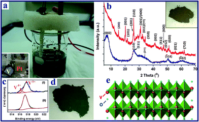 |
| | Fig. 1 (a) Experimental setup of the electrochemical process of anodization of a starting vanadium foil (anode) in NaCl aqueous solution, with Pt foil serving as the cathode (inset photo in a); (b) the XRD patterns of the as-prepared V10O24·nH2O nanoflowers (blue) and the V2O5 product obtained after thermal annealing (red); (c) high resolution XPS spectra of the vanadium element of the vanadium oxide samples: (I) V10O24·nH2O sample; (II) V2O5 product; (d) digital photo of V10O24·nH2O, the photo of the corresponding sample after heat treatment is shown in the inset of b; (e) crystal structure of the layered orthorhombic V2O5. | |
Chemical and physical characterization
The morphologies of the as-synthesized vanadium oxide particles were investigated using a field emission scanning electronic microscope (FESEM, JEOL JSM-6340F). A transmission electron microscope (TEM, JEOL JEM-2010) operating at 200 kV was used to characterize the detailed nanostructures. Elemental analysis was carried out with energy dispersive X-ray (EDX) attachments in the TEM and FESEM. A Shimadzu 6000 X-ray diffractometer with a Cu Kα source was used for phase identification. The oxidation states and surface composition of the vanadium oxide powder at different preparation stages were characterized by X-ray photoelectron spectroscopy (XPS) with an Omicron ESCA Probe with a monochromatic Al Kα source at 1486.6 eV. The positions of the XPS peaks were corrected using the C 1s core level taken to be 285.0 eV as the binding energy (BE) reference.Electrochemical characterization
The coin-type cells were assembled in an argon-filled glove-box, where both moisture and oxygen levels were less than 1 ppm. The cathodes were fabricated by mixing the produced V2O5 powder, carbon black and poly(vinyldifluoride) (PVDF) at a weight ratio of 70![[thin space (1/6-em)]](https://www.rsc.org/images/entities/char_2009.gif) :20:10 in N-methyl-2-pyrrolidone (NMP) solvent. The resulting slurry was then pasted onto the aluminum foil and dried at 70 °C for 12 h. After that, the foil was punched into small disks with a diameter of 14 mm. The mass loading was around 2.0 mg. Lithium foils were used as anodes and the electrolyte solution was made up of 1.0 M LiPF6 in ethylene carbonate (EC)–dimethyl carbonate (DMC) (1:1, w/w). The cells were tested on a NEWARE multi-channel battery test system with galvanostatic charge and discharge in the voltage range of 4.0–2.0 V.
:20:10 in N-methyl-2-pyrrolidone (NMP) solvent. The resulting slurry was then pasted onto the aluminum foil and dried at 70 °C for 12 h. After that, the foil was punched into small disks with a diameter of 14 mm. The mass loading was around 2.0 mg. Lithium foils were used as anodes and the electrolyte solution was made up of 1.0 M LiPF6 in ethylene carbonate (EC)–dimethyl carbonate (DMC) (1:1, w/w). The cells were tested on a NEWARE multi-channel battery test system with galvanostatic charge and discharge in the voltage range of 4.0–2.0 V.3. Results and discussion
3.1. Sample preparation and characterization
The electrochemical reaction of the vanadium foil was conducted in a two electrode system (Fig. 1a and S1†) under a constant voltage of 20 V in 0.8 M NaCl aqueous solution, followed by an aging treatment at room temperature. The XRD pattern of the as-prepared sample (Fig. 1b) shows broad peaks located at around 7.1, 26.0, 34.5, 50.5 and 60.3°, which can be indexed as monoclinic V10O24·nH2O (JCPDS-251006) with lattice parameters a = 11.70, b = 3.63, c = 29.06 Å, and β = 101.5°, in agreement with previous reports.51,52 The water in the interlamellar region of V10O24·nH2O results in the large d002 spacing (ca. 1.24 nm). The oxidation state of vanadium was further confirmed by X-ray photoelectron spectroscopy (XPS) analysis. The V 2p spectrum (Fig. 1c) is fitted into two components. The band at 516.2 eV is assigned to V4+ while the major band, appearing at a higher binding energy (517.7 eV), is assigned to V5+. The ratio of V4+:V5+ is estimated to be 15:85, giving an average V state of 4.85+. This agrees well with the V state in V10O24·nH2O. The obtained vanadium oxide powder was dark green in colour (Fig. 1d). After the thermal annealing treatment, the color changed to dark yellow, as shown in inset of Fig. 1b, and the XPS result in Fig. 1c reveals that V4.83+ is mostly oxidized to V5+. The XRD pattern of the annealed sample (Fig. 1b) also confirms the formation of the orthorhombic V2O5 (JCPDS card 41-1426) phase with lattice parameters of a = 11.522, b = 3.567, and c = 4.375 Å. As shown in Fig. 1e, the final V2O5 product possesses a layered structure consisting of VO5 square pyramids sharing edges and corners along the c-axis of the orthorhombic cell.53 This special layered structure is beneficial for the intercalation/deintercalation of Li ions.Typical field emission scanning electron microscopy (FESEM) images and transmission electron microscopy (TEM) images shown in Fig. 2 give an in-detail morphological study of the as-prepared V10O24·nH2O and V2O5 nanoflowers samples. Fig. 2a and b and S2a and b† show that the as-prepared V10O24·nH2O has a flower-like structure with numerous small nanoribbons, and the particles size is around 200–400 nm. It is noted that our V2O5 sample obtained after annealing at 300 °C still retains the hierarchical flower-like spherical structure and particle size (Fig. 2c and S2c and d†). As shown in Fig. 2d, the as-prepared V10O24·nH2O nanoflowers are highly porous, consisting of one-dimensional (1D) nanoribbons oriented radially outwards on the surface. The plan view of the nanoribbons, as shown in Fig. S3a and b,† reveals that the length and width of ribbons are around 80–180 nm and 5–15 nm, respectively. The corresponding selected electron diffraction (SAED) pattern (inset in Fig. 2d) shows two feeble diffraction rings, which are indexed as the (110)/(111) and (311) diffraction planes of monoclinic V10O24·nH2O. After annealing at 300 °C, the flower-shape of V2O5 sample shows no obvious changes (Fig. 2e), while the long nanoribbons shrink slightly and form a porous flake structure (Fig. S3c and d†). The corresponding SAED pattern (inset in Fig. 2e) shows sharp diffraction rings corresponding to the (200), (001), and (201) diffraction planes of orthorhombic V2O5. The high resolution (HR) TEM image in Fig. 2f displays two sets of fringes with interlayer distances of 0.27 and 0.21 nm, which are related to the spacings of the (011) and (002) planes of orthorhombic V2O5, respectively. Moreover, it is observed that the nanoribbons grow along the [010] direction (Fig. S3e and f†), which agrees well with previous reports by other groups.27,41
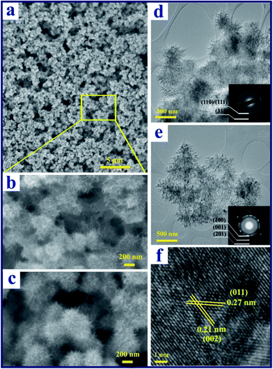 |
| | Fig. 2 (a) Low- and (b) high-magnification FESEM images of the V10O24·nH2O nanoflowers; (c) FESEM image of the V2O5 nanoflowers after thermal annealing; (d) TEM image of the as-prepared V10O24·nH2O nanoflowers; (e) low- and (f) high-magnification TEM images of V2O5 after thermal annealing. The insets in (d) and (e) are the electron diffraction patterns of the samples before and after the thermal annealing process, respectively. | |
3.2. Formation mechanism of vanadium oxide nanoflowers
To shed light on the formation mechanism of the vanadium oxide nanoflowers, the products harvested at different reaction times were examined by a series of measurements including the anodic current– and temperature–time behavior, X-ray photoelectron spectroscopy (XPS), FESEM observation and the colors of the reaction solutions. Fig. 3a shows the anodic current– and solution temperature–time behaviors observed at a constant voltage of 20 V, and the digital photos of the solutions produced at different times are shown in Fig. S4.† The current can be divided into three distinct regions: (1) an initial rapid increase to a steady-state, followed by (2) a slow increase to a maximum, and (3) fast decrease to a steady-state level. This behavior is different from the anodization44 or spallation54 behavior of Ti foil, which shows an initial abrupt current drop owing to the instant increased resistance of the Ti foil due the formation of a compact TiO2 thin film on the electrolyte–metal interface. In contrast, in this work it was found that the anodic current increases almost linearly with reaction time, and no vanadium oxide particles are formed in the initial stage of region (1), which indicates that the V foil is electrochemically dissolved into the NaCl solution instead of first forming an oxide film on the V foil surface. As shown in the digital photo (60 s) of Fig. S4,† the blue vanadium(IV) state (VO2+) ions were firstly formed at the bottom of the beaker by the following reaction:| | | Anode: V − 4e− + H2O = VO2+ + 2H+ | (1) |
Simultaneously, the rapid evolution of hydrogen gas at the cathode was observed as a strong bubbling due to the reaction:| | | Cathode: 2H+ + 2e− = H2 | (2) |
Based on Ohm's law, the total resistance (R) for the anodization system is R = Rc + Ra/e + Re + Rc/e, where Rc is the resistance of the circuit, Ra/e is the resistance of anode–electrolyte interface, Re is the resistance of electrolyte, and Rc/e is the resistance of cathode/electrolyte interface. Ra/e + Re changes all the time and will influence the total R during the electrochemical reaction process. At the initial stage, Re decreases as increasing temperature can improve the ionic mobility of the electrolyte. On the other hand, Ra/e is almost constant as the fresh vanadium foil is exposed to the electrolyte. Consequently, the anodic current (= U/R) increases in region (1) in Fig. 3a under the constant voltage mode. It is also observed that obvious fluctuation of the anode current occurs, which is caused by the instantaneous change of the total resistance (R) and the drastic evolution of gas (via reaction 2) from the cathode. Meanwhile, the gradual increase of the solution temperature caused by the exothermic reaction was observed (Fig. 3a). The increased solution temperature can promote the electrochemical oxidation of vanadium metal to higher valence. As the reaction time proceeds to 120 s, a khaki color of the electrolyte solution started to appear (digital photo in Fig. S4†), which indicates that the vanadium metal is electrochemically oxidized to the highest valence (V5+) state via:| | | V − 5e− + H2O = VO2+ + 4H+ | (3) |
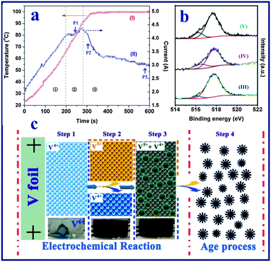 |
| | Fig. 3 (a) Real-time observation of solution temperature (curve I) and anodization current (curve II) of vanadium foil anodized at a constant voltage of 20 V in a NaCl aqueous solution. (b) High resolution XPS spectra of the vanadium element of the vanadium oxide samples obtained at different stages of the reaction process: after electrochemical reaction for 10 min (curve III), after aging treatment for 24 h (curve IV), and after aging treatment for 48 h (curve V). (c) The proposed scheme for the formation of the hierarchical vanadium oxide nanoflowers. Step 1: formation of the VO2+ ion in the electrolyte; step 2: formation of the V4+ and V5+ mixture solution at high temperature; step 3: formation of mixed-valence vanadium oxide powder at high temperature; step 4: aging process of the vanadium oxide particles. | |
In region (2), the anodization rate of the vanadium foil reached a maximum value as indicated by the anodic current vs. time plot. During this stage, as shown in Fig. S5a,† vanadium oxide nanoparticles with sizes of 100–200 nm started to appear at point P1 in Fig. 3a (∼240 s). In the last region (3), it was observed that the vanadium foil lost its metallic lustre (Fig. S6†), indicating the growth of a vanadium oxide film on the surface of the vanadium foil. This was coupled with an increase in the resistance of the interface between the anode and electrolyte (i.e., the anodic current decreased). The anodization current was therefore dramatically decreased. FESEM images of the vanadium oxide samples taken at points P2 (∼300 s) and P3 (∼600 s) (Fig. S5b and c†) indicate that no obvious morphological changes occurred. Furthermore, it was found that the solution temperature increased linearly with the reaction time and finally reached the boiling point of water at around 99.8 °C. According to previous work, most of the vanadium(IV) state (VO2+) ions are stable even at the high temperature (e.g., up to 180 °C) and high pressure conditions used for the preparation of the H2V3O8 (ref. 52) or VO2 nanostructures.51 Thus, we believe that the VO2+ ions are stable during the electrochemical process under relatively mild conditions. In addition, due to the rapid H2 gas evolution from the cathode, a large amount of hydroxide ions are generated, which promotes the formation of V2O5−x·nH2O particles due to the direct reaction between the mixed-valence (IV,V) vanadium ions and OH− at high solution temperature. We examined the oxidation state of the vanadium element of vanadium oxide powder after the electrochemical reaction (i.e., at 600 s). The XPS analysis result (Fig. 3b-III) indicates a mixture of V5+ and V4+ (V4+:V5+ = 7:93, i.e., average V state: 4.93+). The formation of V2O4.93 was a result of the following precipitation reaction:
| | | 2VO2+ + 2xVO2+ + (2 + 4x)OH− → (1 + x)V2O4.93 + (1 + 2x)H2O (x = 0.075) | (4) |
where the VO
2+ was the product of
eqn (1), VO
2+ was the product of
eqn (3), and OH
− was derived from H
2 evolution.
After the electrochemical process, the obtained vanadium oxide (V2O4.93) nanoparticles were kept in the electrolyte for the aging process for 2 days at room temperature. An interesting phenomenon was found during this period. The fresh vanadium oxide nanoparticles can easily be further reacted with multiple oxidation states of vanadium ions during the aging process at room temperature, since there are a large number of vanadium ions (VO2+ and VO2+) in the electrolyte solution after the electrochemical reaction. The FESEM images of intermediates collected at different aging periods clearly show the evolution process of nanoparticles to flower-like structures (Fig. S5d–f†). After aging for 12 h, small nanoribbons were formed on the surfaces of the nanoparticles, which led to the formation of flower-like structures with sizes of 200–400 nm (Fig. S5d†). The nanoparticles–nanoflowers transformation gradually takes place due to the continuing nucleation–growth process, and the flower-like morphology of the vanadium oxide particles becomes clearly observable after 24 h (Fig. S5e†). The XPS result in Fig. 3b-IV reveals that the area of the V4+ species increased (ca. 19%) compared with fresh vanadium oxide (Fig. 3b-III), which further confirms that the VO2+ ion is involved in chemical reaction during the aging process. When the reaction time reached 36–48 h, almost all of the nanoparticles had been transformed to the flower-like structure, with the surface covered by numerous nanoribbons as shown in Fig. S5f† and Fig. 2a and b. The oxidation state of the vanadium oxide sample after aging for 48 h (Fig. 3b-V) is similar to that of the sample aged for 24 h (Fig. S2-II†), while the percentage of the V4+ species is slightly decreased to ca. 15%. This may be due to the decrease of the concentration of VO2+ ions in the aging solution during the chemical reaction. Finally, the formation of flower-like V10O24·nH2O is via:
| | | 8VO2+ + 2VO2+ + 12OH− → V10O24·nH2O + (6 − n)H2O | (5) |
On the basis of the above experimental results, we propose the following formation mechanism for the formation of the hierarchical vanadium oxide nanoflowers. The whole process is through the synergistic effect of electrochemical dissolution, a hydrothermal-like chemical reaction and an aging process as illustrated in Fig. 3c. In stage 1, fast anodic dissolution of the vanadium foil surface takes place instantly in the NaCl solution under the applied electrical field, forming blue colored VO2+ ions in the aqueous solution. No vanadium oxide particles are formed at this stage. The solution temperature is increased due to the exothermic electrochemical reaction, which accelerates the anodic dissolution rate, since the current increases lineally with time. In stage 2, at a relatively higher solution temperature (ca. 45 °C, 2 min in Fig. 3a), vanadium could be oxidized to higher valence VO2+ (yellow colour), resulting in a mixed-valence vanadium ion solution. Meanwhile, strong hydrogen gas evolution from the cathode results an a higher concentration of OH− ions in the electrolyte. Such a condition would facilitate a hydrothermal-like chemical reaction between the multi-oxidation state vanadium ions and the hydroxide groups at higher temperature. Thereafter in stage 3, particles are generated continually from the dark yellow electrolyte solution after 4 min (ca. 82 °C, Fig. 3a), and mixed-valence V2O4.93 nanoparticles (Fig. S5c†) with uniform size distribution are obtained after electrochemical reaction. In stage 4, the aging treatment, the existing VO2+ and VO2+ ions in the solution continuously react with OH− ions in the electrolyte solution to form nuclei of V10O24 nanostructures on the surface of the existing vanadium oxide nanoparticles.
3.3. Electrochemical performance of the V2O5 nanoflowers
V2O5 nanoflowers (Fig. 2e), obtained after annealing V10O24·nH2O samples, were evaluated as cathodes for Li-ion batteries using a half cell configuration. The surface area of the V2O5 nanoflowers is around 22.7 m2 g−1 with a pore volume of around 0.12 cm3 g−1 (Fig. S7†). Fig. 4a shows the galvanostatic discharge (Li+ insertion) and charge (Li+ extraction) voltage profiles of the V2O5 nanoflowers electrode at a current density of 50 mA g−1 (0.2 C) between 4.0 and 2.0 V vs. Li+/Li. The typical plateaus corresponding to the phase transitions of crystalline V2O5 were observed. Lithium intercalation into the interlayer space of V2O5 along the ab plane follows the equation V2O5 + xLi+ + xe− → LixV2O5.27,55,56 Several phases of LixV2O5 have been observed depending on the lithium content: the α-phase for x < 0.1, the ε-phase for 0.35 < x < 0.7 and the δ-phase for 0.7 < x < 1.0. At 1.0 < x < 1.4, the γ-phase forms. Further reaction leads to the formation of a new phase of ζ, which coexists with the γ-phase with x up to 2.57 These phase transitions are reversible in the subsequent charge processes. As shown in Fig. 4a, the V2O5 nanoflowers electrode exhibited an initial discharge capacity of 275 mAh g−1 and a subsequent charge capacity of 275 mAh g−1, indicating no irreversible capacity loss. In the 20th cycle, the multi-step charge–discharge behavior was still observed, which suggests that the phase transition processes are highly reversible, without formation of the irreversible rock-salt phase of ω-Li3V2O5.55 The coulombic efficiency was consistently maintained at ∼100% for the first 20 cycles. Fig. 4b shows the specific discharge capacities of the V2O5 electrode for the first 50 cycles at a current density of 50 mA g−1. A discharge capacity of 239 mAh g−1 was delivered at the 50th cycle, corresponding to 87% of the initial capacity, and the capacity fading rate is therefore estimated to be 0.26% per cycle. In comparison, the cycling performance of spherical V2O5 with sizes of 100–300 nm prepared by a polyvinyl pyrrolidone (PVP)-assisted hydrolysis method was also evaluated as a reference. The phase and morphology of these spherical V2O5 reference samples were examined by XRD and FESEM (Fig. S8†). The spherical V2O5 nanoparticles were investigated as cathode materials in a half cell at 0.2 C. As shown in Fig. 4b, the spherical V2O5 electrode suffers from rapid capacity fading. The specific capacity decreased from 262 mAh g−1 (discharge capacity) in the first cycle, to 106 mAh g−1 in the 50th cycle, resulting in a capacity fading rate of 1.19% per cycle. Furthermore, the cycling stability of V2O5 nanoflowers is also better than many reported advanced V2O5-based cathodes in the same voltage window.34,40 For example, electrospun ultra-long V2O5 nanowires display an initial discharge capacity of 275 mAh g−1 at 0.1 C, which rapidly decreases to 187 mAh g−1 in the 50th cycle (capacity fading rate: 0.64% per cycle).40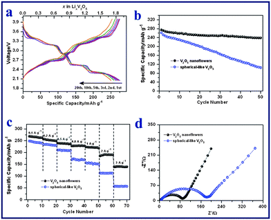 |
| | Fig. 4 (a) Galvanostatic charge–discharge voltage profiles of V2O5 nanoflowers at a current density of 50 mA g−1. (b) Cycling performances of V2O5 nanoflowers and spherical V2O5 electrodes at a current density of 50 mA g−1. (c) Rate capabilities of V2O5 nanoflowers and spherical V2O5 electrodes at current densities of 100 to 3000 mA g−1. (d) Electrochemical impedance spectra of the two electrodes measured at the 4th fully discharged state. | |
For practical applications, a good C-rate performance is desirable in developing high power/fast charging lithium ion batteries. The cycling responses of the V2O5 nanoflowers electrode at different C rates were evaluated and are shown in Fig. 4c. It delivers discharge capacities of 269, 256, 239, 228, 223 and 188 mAh g−1 during the 2nd cycle at current densities of 100 (0.3 C), 200 (0.7 C), 500 (1.7 C), 800 (2.7 C), 1000 (3.4 C) and 2000 mA g−1 (6.8 C), respectively. Even at a high current density of 3000 mA g−1 (10 C), the electrode can still achieve a high discharge capacity of 140 mAh g−1 in the 2nd cycle. The retentions of rate capacity are calculated to be 93% (0.7 C), 87% (1.7 C), 83% (2.7 C), 81% (3.4 C), 69% (6.8 C) and 50% (10 C), based on the capacity of 269 mAh g−1 at 0.3 C. In contrast, the capacities of spherical V2O5 drop much more sharply at increased current densities (Fig. 4c). For example, the capacity retention is only 23% (i.e., 57 mAh g−1) at 10 C for the spherical V2O5 electrode. The inferior Li storage properties of the spherical V2O5 cathode are mainly attributed to its poor kinetics of charge transfer, as verified by the electrochemical impedance spectra (Fig. 4d). The spherical V2O5 cathode shows a larger semi-circle radius in the Nyquist plots as compared to that of V2O5 nanoflowers cathode, which indicates a higher charge-transfer resistance. The excellent electrochemical performance of the V2O5 nanoflowers electrode is believed to result from its unique hierarchical architecture. The highly porous flower-like structure allows the effective infiltration of the electrolyte, shorter Li+ diffusion paths and the accommodation of the strain generated during the lithium insertion and extraction process.
4. Conclusions
In summary, a facile and economical method to synthesize hierarchical vanadium oxide nanoflowers at ambient conditions was demonstrated in this work. The preparation makes use of a fast electrochemical dissolution process (10 min) in NaCl aqueous solution, followed by an aging treatment at room temperature to generate multi-valence vanadium oxide nanoflowers with uniform particle distribution. The subsequently annealed vanadium pentoxide maintains the hierarchical nanoflowers structure, and has shown excellent performance as a cathode material for lithium-ion batteries. The porous V2O5 nanoflower sample displays higher initial discharge capacity (275 mAh g−1), and better cycling stability (capacity fading rate: 0.26% per cycle) at 50 mA g−1 compared with a spherical V2O5 sample. It also shows superior high-rate capability, with reversible capacities of up to 140 mAh g−1 at a 10 C rate. This excellent electrochemical performance is ascribed to its unique highly porous hierarchical flower-like architecture that could easily facilitate electrolyte penetration and Li+ diffusion. At the same time, such a structure could accommodate well the strain arising from the Li+ intercalation/de-intercalation, a key factor behind performance degradation in lithium-ion batteries.Acknowledgements
The authors thank the Environment and Water Industry Programme Office under the National Research Foundation of Singapore (grant no. MEWR651/06/160), AcRF Tier 1 RG 31/08 of MOE (Singapore), NRF2009EWT-CERP001-026 (Singapore), the Singapore Ministry of Education (MOE2010-T2-1-017), A*STAR SERC grant 1021700144 and Singapore MPA 23/04.15.03 grant for the financial support of this work.Notes and references
- A. Magasinski, P. Dixon, B. Hertzberg, A. Kvit, J. Ayala and G. Yushin, Nat. Mater., 2010, 9, 353–358 CrossRef CAS.
- C. Z. Wu and Y. Xie, Energy Environ. Sci., 2010, 3, 1191–1206 CAS.
- Y. S. Hu, P. Adelhelm, B. M. Smarsly, S. Hore, M. Antonietti and J. Maier, Adv. Funct. Mater., 2007, 17, 1873–1878 CrossRef CAS.
- L. Zhou, D. Y. Zhao and X. W. Lou, Adv. Mater., 2012, 24, 745–748 CrossRef CAS.
- Z. Y. Wang, Z. C. Wang, S. Madhavi and X. W. Lou, J. Mater. Chem., 2012, 22, 2526–2531 RSC.
- J. Liu, S. Z. Qiao, S. B. Hartono and G. Q. Lu, Angew. Chem., Int. Ed., 2010, 49, 4981–4985 CrossRef CAS.
- Y. G. Guo, J. S. Hu and L. J. Wan, Adv. Mater., 2008, 20, 2878–2887 CrossRef CAS.
- Y. Yao, M. T. McDowell, I. Ryu, H. Wu, N. A. Liu, L. B. Hu, W. D. Nix and Y. Cui, Nano Lett., 2011, 11, 2949–2954 CrossRef CAS.
- J. Fan, T. Wang, C. Z. Yu, B. Tu, Z. Y. Jiang and D. Y. Zhao, Adv. Mater., 2004, 16, 1432–1436 CrossRef CAS.
- Y. Tang, P. Wee, Y. Lai, X. Wang, D. Gong, P. D. Kanhere, T.-T. Lim, Z. Dong and Z. Chen, J. Phys. Chem. C, 2012, 116, 2772–2780 CAS.
- J. Zhao and Y. Wang, J. Phys. Chem. C, 2012, 116, 11867–11876 CAS.
- C. Z. Wu, Y. Xie, L. Y. Lei, S. Q. Hu and C. Z. OuYang, Adv. Mater., 2006, 18, 1727–1732 CrossRef CAS.
- J. S. Chen, Y. L. Tan, C. M. Li, Y. L. Cheah, D. Y. Luan, S. Madhavi, F. Y. C. Boey, L. A. Archer and X. W. Lou, J. Am. Chem. Soc., 2010, 132, 6124–6130 CrossRef CAS.
- Y. Y. Zhang, Y. X. Tang, S. Y. Yin, Z. Y. Zeng, H. Zhang, C. M. Li, Z. L. Dong, Z. Chen and X. D. Chen, Nanoscale, 2011, 3, 4074–4077 RSC.
- Y. G. Guo, Y. S. Hu, W. Sigle and J. Maier, Adv. Mater., 2007, 19, 2087–2091 CrossRef CAS.
- S. Yin, Y. Zhang, J. Kong, C. Zou, C. M. Li, X. Lu, J. Ma, F. Y. C. Boey and X. Chen, ACS Nano, 2011, 5, 3831–3838 CrossRef CAS.
- X. W. Lou, L. A. Archer and Z. C. Yang, Adv. Mater., 2008, 20, 3987–4019 CrossRef CAS.
- Y. Liu, M. Clark, Q. Zhang, D. Yu, D. Liu, J. Liu and G. Cao, Adv. Energy Mater., 2011, 1, 194–202 CrossRef CAS.
- C. Xu, Y. Zeng, X. H. Rui, N. Xiao, J. X. Zhu, W. Y. Zhang, J. Chen, W. L. Liu, H. T. Tan, H. H. Hng and Q. Y. Yan, ACS Nano, 2012, 6, 4713–4721 CrossRef CAS.
- C. O'Dwyer, V. Lavayen, D. A. Tanner, S. B. Newcomb, E. Benavente, G. Gonzalez and C. M. S. Torres, Adv. Funct. Mater., 2009, 19, 1736–1745 CrossRef CAS.
- J. Liu, H. Xia, D. F. Xue and L. Lu, J. Am. Chem. Soc., 2009, 131, 12086–12087 CrossRef CAS.
- Y. Wang and G. Z. Cao, Adv. Mater., 2008, 20, 2251–2269 CrossRef CAS.
- A.-M. Cao, J.-S. Hu, H.-P. Liang and L.-J. Wan, Angew. Chem., Int. Ed., 2005, 44, 4391–4395 CrossRef CAS.
- X. Chen, E. Pomerantseva, P. Banerjee, K. Gregorczyk, R. Ghodssi and G. Rubloff, Chem. Mater., 2012, 24, 1255–1261 CrossRef CAS.
- M. Koltypin, V. Pol, A. Gedanken and D. Aurbach, J. Electrochem. Soc., 2007, 154, A605–A613 CrossRef CAS.
- J. F. Liu, Q. H. Li, T. H. Wang, D. P. Yu and Y. D. Li, Angew. Chem., Int. Ed., 2004, 43, 5048–5052 CrossRef CAS.
- C. K. Chan, H. L. Peng, R. D. Twesten, K. Jarausch, X. F. Zhang and Y. Cui, Nano Lett., 2007, 7, 490–495 CrossRef CAS.
- S. L. Chou, J. Z. Wang, J. Z. Sun, D. Wexler, M. Forsyth, H. K. Liu, D. R. MacFarlane and S. X. Dou, Chem. Mater., 2008, 20, 7044–7051 CrossRef CAS.
- G. C. Li, S. P. Pang, L. Jiang, Z. Y. Guo and Z. K. Zhang, J. Phys. Chem. B, 2006, 110, 9383–9386 CrossRef CAS.
- C. V. S. Reddy, S. A. Wicker, E. H. Walker, Q. L. Williams and R. R. Kalluru, J. Electrochem. Soc., 2008, 155, A599–A602 CrossRef CAS.
- X. Rui, J. Zhu, W. Liu, H. Tan, D. Sim, C. Xu, H. Zhang, J. Ma, H. H. Hng, T. M. Lim and Q. Yan, RSC Adv., 2011, 1, 117–122 RSC.
- T. Y. Zhai, H. M. Liu, H. Q. Li, X. S. Fang, M. Y. Liao, L. Li, H. S. Zhou, Y. Koide, Y. Bando and D. Goberg, Adv. Mater., 2010, 22, 2547–2552 CrossRef CAS.
- S. Q. Wang, Z. D. Lu, D. Wang, C. G. Li, C. H. Chen and Y. D. Yin, J. Mater. Chem., 2011, 21, 6365–6369 RSC.
- S. Wang, Z. Lu, D. Wang, C. Li, C. Chen and Y. Yin, J. Mater. Chem., 2011, 21, 6365–6369 RSC.
- X. Rui, J. Zhu, D. Sim, C. Xu, Y. Zeng, H. H. Hng, T. M. Lim and Q. Yan, Nanoscale, 2011, 3, 4752–4758 RSC.
- S. Q. Wang, S. R. Li, Y. Sun, X. R. Feng and C. H. Chen, Energy Environ. Sci., 2011, 4, 2854–2857 CAS.
- C. V. S. Reddy, J. Wei, Z. Quan-Yao, D. Zhi-Rong, C. Wen, S. Mho and R. R. Kalluru, J. Power Sources, 2007, 166, 244–249 CrossRef CAS.
- K. Takahashi, S. J. Limmer, Y. Wang and G. Cao, J. Phys. Chem. B, 2004, 108, 9795–9800 CrossRef CAS.
- M. C. Wu and C. S. Lee, J. Solid State Chem., 2009, 182, 2285–2289 CrossRef CAS.
- L. Q. Mai, L. Xu, C. H. Han, Y. Z. Luo, S. Y. Zhao and Y. L. Zhao, Nano Lett., 2010, 10, 4750–4755 CrossRef CAS.
- H. Fu, X. Jiang, X. Yang, A. Yu, D. Su and G. Wang, J. Nanopart. Res., 2012, 14, 1–14 Search PubMed.
- C. C. Hu, K. H. Chang, C. M. Huang and J. M. Li, J. Electrochem. Soc., 2009, 156, D485–D489 CrossRef CAS.
- G. B. Stefanovich, A. L. Pergament, A. A. Velichko and L. A. Stefanovich, J. Phys.: Condens. Matter, 2004, 16, 4013–4024 CrossRef CAS.
- G. K. Mor, O. K. Varghese, M. Paulose, K. Shankar and C. A. Grimes, Sol. Energy Mater. Sol. Cells, 2006, 90, 2011–2075 CrossRef CAS.
- S. P. Albu, A. Ghicov, J. M. Macak, R. Hahn and P. Schmuki, Nano Lett., 2007, 7, 1286–1289 CrossRef CAS.
- D. Wang, T. Hu, L. Hu, B. Yu, Y. Xia, F. Zhou and W. Liu, Adv. Funct. Mater., 2009, 19, 1930–1938 CrossRef CAS.
- D. A. Wang, T. C. Hu, L. T. Hu, B. Yu, Y. Q. Xia, F. Zhou and W. M. Liu, Adv. Funct. Mater., 2009, 19, 1930–1938 CrossRef CAS.
- Y. X. Tang, D. G. Gong, Y. K. Lai, Y. Q. Shen, Y. Y. Zhang, Y. Z. Huang, J. Tao, C. J. Lin, Z. L. Dong and Z. Chen, J. Mater. Chem., 2010, 20, 10169–10178 RSC.
- S. Hornkjøl and I. M. Hornkjøl, Electrochim. Acta, 1991, 36, 577–580 CrossRef.
- Y. Yang, S. P. Albu, D. Kim and P. Schmuki, Angew. Chem., Int. Ed., 2011, 50, 9071–9075 CrossRef CAS.
- G. Li, K. Chao, C. Zhang, Q. Zhang, H. Peng and K. Chen, Inorg. Chem., 2009, 48, 1168–1172 CrossRef CAS.
- K. H. Chang and C. C. Hu, Acta Mater., 2007, 55, 6192–6197 CrossRef CAS.
- M. Sathiya, A. S. Prakash, K. Ramesha, J. M. Tarascon and A. K. Shukla, J. Am. Chem. Soc., 2011, 133, 16291–16299 CrossRef CAS.
- Y. X. Tang, Y. K. Lai, D. G. Gong, K. H. Goh, T. T. Lim, Z. L. Dong and Z. Chen, Chem.–Eur. J., 2010, 16, 7704–7708 CrossRef CAS.
- C. Delmas, H. Cognacauradou, J. M. Cocciantelli, M. Menetrier and J. P. Doumerc, Solid State Ionics, 1994, 69, 257–264 CrossRef CAS.
- D. Gourier, A. Tranchant, N. Baffier and R. Messina, Electrochim. Acta, 1992, 37, 2755–2764 CrossRef CAS.
- J. M. Cocciantelli, M. Menetrier, C. Delmas, J. P. Doumerc, M. Pouchard and P. Hagenmuller, Solid State Ionics, 1992, 50, 99–105 CrossRef CAS.
Footnotes |
| † Electronic supplementary information (ESI) available: Fig. S1–S8. See DOI: 10.1039/c2ta00351a |
| ‡ These authors contributed equally to this work. |
|
| This journal is © The Royal Society of Chemistry 2013 |