 Open Access Article
Creative Commons Attribution 3.0 Unported Licence
In-chip fabrication of free-form 3D constructs for directed cell migration analysis†
Mark Holm
Olsen
a,
Gertrud Malene
Hjortø
a,
Morten
Hansen
b,
Özcan
Met
bc,
Inge Marie
Svane
bc and
Niels B.
Larsen
*a
aDepartment of Micro- and Nanotechnology, DTU Nanotech, Technical University of Denmark, Ørsteds Plads 345E, DK-2800 Kgs. Lyngby, Denmark. E-mail: niels.b.larsen@nanotech.dtu.dk; Fax: +45 4588 7762; Tel: +45 4525 8161
bCenter for Cancer Immune Therapy (CCIT), Department of Hematology, Copenhagen University Hospital, Herlev, Denmark
cDepartment of Oncology, Copenhagen University Hospital, Herlev, Denmark
First published on 30th September 2013
Abstract
Free-form constructs with three-dimensional (3D) microporosity were fabricated by two-photon polymerization inside the closed microchannel of an injection-molded, commercially available polymer chip for analysis of directed cell migration. Acrylate constructs were produced as woodpile topologies with a range of pore sizes from 5 × 5 μm to 15 × 15 μm and prefilled with fibrillar collagen. Dendritic cells seeded into the polymer chip in a concentration gradient of the chemoattractant CCL21 efficiently negotiated the microporous maze structure for pore sizes of 8 × 8 μm or larger. The cells migrating through smaller pore sizes made significantly more turns than those through larger pores. The introduction of additional defined barriers in the microporous structure resulted in dendritic cells making more turns while still being able to follow the chemoattractant concentration gradient.
Introduction
Mammalian cell migration studies have traditionally been performed on planar culture substrates of glass or plastics, a two-dimensional (2D) environment not very similar to the 3D extracellular matrix environment of the animal body. Numerous publications in the past decades have reported how cell adhesion and migration mechanisms differ in 3D versus 2D microenvironments.1–3 A strong dependence on 3D confinement is particularly notable for fast-moving immune cells, as recently demonstrated for neutrophils and T blasts in vitro4 and for dendritic cells in vivo.5 Migration analysis studies in 3D have extensively used self-assembling extracellular matrix components,6 in particular, fibrillar collagen, to form random microporous constructs typically located within macroscopic lateral confinements to permit the establishment of a defined concentration gradient directing the cell migration.7 Approaches to improve the structural homogeneity have included templating of migration constructs on 3D close-packed microbead arrays to engineer more uniform sizes of cavities and connecting pores.8,9 Widely used Transwell assays (modified Boyden chambers)10 capture some of the 3D characteristics by confining cell movement to an unbranched short tunnel of well-defined width and of typical length much shorter than the extended length of the cells being investigated. Thus, Transwell assays are useful improvements over the purely 2D motion on planar substrates, but with obvious analytical shortcomings. First, they cannot mimic the 3D connectivity of real tissue microenvironments in a defined way. Second, individual cells will not experience complete 3D confinement at any time point due to the short tunnel length. Third, cell migration only proceeds perpendicular to the porous culture surface which does not allow for studying variations in the migration process, but only an endpoint analysis of the number of migrated cells. Recent reports have overcome some of the Transwell assay shortcomings by using poly(dimethyl siloxane) (PDMS) based soft lithography to produce microchannel arrays of varying dimensions for the analysis of immune cell or cancer cell migration.11–15 These studies have provided important insight on the intracellular mechanisms governing confined migration. However, easily accessible soft lithography methods are experimentally restricted to single or few layer topologies that cannot mimic the complex in vivo environments. We demonstrate how to overcome these limitations in cell migration analysis using two-photon polymerization to write the targeted 3D environments of arbitrary complexity with micrometer scale resolution. The resulting structures are made available for cell biologists in a ready-to-use and cost-efficient format by fabricating the cell migration constructs inside a commercially available closed microfluidic chip designed for cell migration analysis.The ideal construct for migration analysis should (a) result in cell migration behavior that functionally resembles the in vivo behavior as closely as possible, (b) be highly reproducible to enable reliable interpretation of the cell responses, and (c) support the presence of a stable concentration gradient of signaling molecules across the construct to perform directed cell migration (chemotaxis) studies. The natural microenvironment is a highly complex combination of topological, chemical, and mechanical cues that is unlikely to be mimicked exactly in a laboratory setting. As a functional approximation, in vitro microenvironments may be designed with varying degrees of microstructural complexity to explore cellular navigation abilities, possibly after the addition of natural extracellular components to provide biochemical and ultrastructural signaling. Designs inducing the most in vivo-like migration can then be selected for larger scale fabrication to be used in cell preparation optimization or cell migration validation. Both applications are of relevance to cell-based immunotherapy by dendritic cells as we target here. Thus, constructs must be fabricated using a method capable of reproducible writing of 3D structures with a resolution of sub-cellular dimensions, preferably in combination with extracellular matrix components. The method should also be of sufficiently low cost per analysis to be used as a routine tool in cell biological work that typically calls for a large number of experiments to achieve adequate statistical significance. The final constructs should permit optical visualization of the migrating cells to analyze their individual detailed migration pathways within a stable concentration gradient maintained for hours to days.
Cell migration through connective tissue is of key interest in several biological areas including immune responses and cancer invasion. The main load-bearing part of the extracellular matrix in connective tissue is fibrillar collagen, constituting >90% of the extracellular matrix protein and forming a protein hydrogel with abundant fibrils and fibers of sub-micrometer to micrometer diameters.16 Consequently, most 3D migration studies have used collagen-based systems. Recent reports comparing the in vivo topology of connective tissue in mice to in vitro models showed heterogeneous in vivo environments of microporous pathways (from 1–20 μm in diameter) between dense regions inaccessible to fast-migrating immune cells, a heterogeneity only poorly reproduced by in vitro models.5,17 Additionally, fiber and fibril diameters and spacings in in vitro collagen matrices vary a lot within each sample and between samples. Such topological variation prohibits reliable interpretation of possibly significant cell-to-cell differences in migratory properties.
The microstructural shortcomings of natural, self-assembled polymers have in recent years been overcome by introducing non-linear optical methods for direct 3D writing. Two-photon processes can induce spatially localized chemical reactions in 3D with sub-micrometer accuracy, either for locally forming or breaking chemical bonds in synthetic or natural polymers. Several groups have employed two-photon microscopy for locally photodegrading cell-loaded collagen gels or cross-linked poly(ethylene glycol) (PEG) gels to produce defined channel networks for cell migration.18,19 This elegant solution has the disadvantage of requiring the preloading of the cells in the collagen or PEG hydrogel, and thus local access to advanced two-photon microscopy systems. In addition, the loading of cells into the hydrogel material until two-photon-induced release may affect their phenotype and their viability.
Two-photon polymerization (2PP) uses a two-photon microscope to locally polymerize the material into arbitrary 3D shapes with sub-micrometer resolution.20–22 Such constructs are structurally stable and may be produced at dedicated fabrication facilities independent of their final biological use.23 Recent reports have shown that 2PP can produce cellular-sized constructs of low structural complexity for studying directed cell migration in an open custom built microchamber system.24,25 Broader use of the technology may be anticipated from increasing the structural complexity, decreasing the minimum feature size, and integrating the constructs in a closed standard chip design.
Very recently, the extraordinary ability of 2PP to polymerize and structure 3D objects within a closed microchannel system was reported for use as in-chip filters or as in-chip enzymatic reactors.26,27 Here, we demonstrate the fabrication of reproducible 3D structures with cell-sized pores by 2PP inside the closed channel of a commercially available disposable polymer microfluidic chip (Fig. 1) designed for chemotaxis analysis in non-structured hydrogel materials. The generated “woodpile” structures are employed to investigate the migration behavior of mature human dendritic cells (DCs) towards a chemoattractant (CCL21) in complex microtopologies of varying defined dimensions. The use of a chip system with integrated reservoir structures next to the targeted microchannel (Fig. 2) has added 2PP benefits of easy and fast pre-exposure loading and post-exposure structure development of the low-viscosity acrylate resin. Loading and development are achieved in minutes instead of hours to days as previously reported for procedures including pre-exposure soft baking steps and cumbersome development in long closed-channel systems.26 Writing times of hours limit production volume. However, the in-chip system can be re-used for biological analysis after a simple and short enzymatic (collagenase) treatment which compensates for the higher price of the serial 2PP fabrication technique. The dedicated chip design supports a stable chemoattractant concentration gradient for up to 48 h,28 and the thin chip bottom layer is optimized for high magnification microscopy of the migrating cells.
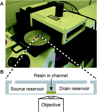 | ||
| Fig. 1 (A) A two-photon polymerization system with a chip mounted in a custom-made aluminum adaptor. (B) Cross section of the chip showing the reservoirs (65 μL) and channel (<1 μL) geometry with the channel loaded with resin (yellow). The thin chip bottom layer is optimized for microscopy with high numerical aperture objectives and is thus ideal for high-resolution 2PP fabrication. | ||
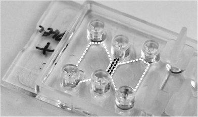 | ||
| Fig. 2 Photograph of the ibidi μ-Slide Chemotaxis3D chip (76 mm × 25 mm) used as a platform for two-photon polymerization of cell-sized 3D microstructures in the center channel (black dashed lines) between chemoattractant-containing and -free reservoirs (white dashed areas). | ||
Materials and methods
In-chip fabrication of cell migration constructs
Two-photon polymerization was performed on a Nanoscribe Photonic Professional system (Nanoscribe, Eggenstein-Leopoldshafen, Germany). The Nanoscribe system uses a 780 nm Ti–sapphire laser emitting 150 fs pulses at 100 MHz with a maximum power of 100 mW (20 mW at the sample surface) and is equipped with a 100×, 1.4 NA (numerical aperture) oil immersion objective. The substrate is placed in a holder that fits into a piezoelectric x/y/z stage. Writing is done by controlling the laser in time and moving the stage in x, y and z. Structures were produced in a liquid acrylate-based resin (IP-L 780, Nanoscribe). Writing speeds ranged from 400 μm s−1 to 1200 μm s−1 depending on the depth of writing into the resin: larger writing depths caused loss of light intensity, and the writing speed was reduced to retain complete cross-linking and structural rigidity. All structures were written in order from the largest to the smallest writing depths to minimize intense scattering of the laser beam from already polymerized structures. Thus, the first layers written are furthest away from the objective and the surface of the substrate. In open systems, this technique requires the initial writing of support pillars and beams in the opposite writing order to prevent the polymerized lines of the targeted structure from floating away in the liquid resin. Supports were not required for in-chip writing since the initial structure could be anchored to the channel ceiling.Initial experiments used circular Ø 30 mm × 0.17 mm glass cover slips as substrates in an open system. Briefly, the cover slips were cleaned with acetone and 2-propanol (both Sigma-Aldrich, St. Louis, MO) before a drop of resin was placed on the top and the substrate was fixed in the holder with 4 drops of Fixogum (Marabu, Tamm, Germany). After exposure, the substrates were developed in 2-propanol by submersion in a beaker for 20 min and washed with acetone before drying with compressed air.
The polymer chip (μ-Slide Chemotaxis3D, ibidi, Martinsried, Germany) was mounted on the stage via fixation with Fixogum to a custom-made aluminum adaptor (see Fig. 1A). A drop of resin was placed on one channel inlet for the channel to fill by capillary forces. Residual resin on the inlet was removed with tissue. Identical writing parameters were used for the chip and the cover slip substrates. An initial measurement of the channel dimensions was performed by the autofocus system to determine the required structure height to fill the channel. Development was done by filling the reservoirs with 2-propanol and emptying after 10 min. The process was repeated three times. After development, the reservoirs and channels were sterilized by flushing with ethanol in a flow bench and left to dry for 24 h.
Confocal micrograph stacks were acquired with a Zeiss LSM 5 microscope (Carl Zeiss, Oberkochen, Germany) with either a 63×, 1.4 NA oil immersion objective or a 40×, 1.2 NA water immersion objective using excitation light at 488 nm and collecting the emitted light from 515–550 nm. The recorded stacks were processed into 3D reconstructions using ImageJ.29
Generation of monocyte-derived dendritic cells
CellGro DC serum-free medium, GM-CSF, IL-4, IL-1β, TNF-α and IL-6 were all obtained from CellGenix (Freiburg, Germany). PGE2 was obtained from Sigma-Aldrich. Iscove's modified Dulbecco's medium (IMDM) and human AB-serum were acquired from Lonza (Basal, Switzerland), and penicillin/streptomycin (P/S) and fetal bovine serum (FBS) were acquired from Invitrogen (Life Technologies, Paisley, UK). NaHCO3 solution (7.5%), 10× MEM solution, and collagenase (Clostridium histolyticum, cell culture tested) were from Sigma-Aldrich, PureCol (collagen I) solution was from Advanced Biomatrix (San Diego, CA) and CCL21 was from R&D Systems (Minneapolis, MN).Leukapheresis was done on healthy blood donors after informed consent followed by separation using elutriation (Terumo BCT, Lakewood, CO) and subsequent freezing of monocytes (80–90% pure as determined by flow cytometry on CD14). Thawed monocytes with viability >99% were cultured for five days in culture plates (Ø 21 cm) at 5 × 10⁵ cells ml−1 in CellGro DC medium supplemented with 1000 U ml−1 GM-CSF and 250 U ml−1 IL-4 to produce immature DCs. Maturation of DCs was induced for 2 days by adding 1000 U ml−1 TNF-α, 1000 U ml−1 IL-1β, 1000 U mL−1 IL-6, and 1 μg ml−1 PGE2.30 Harvest of DCs was performed by aspiration followed by cold incubation of the remaining cells in PBS with EDTA (5 mM) and subsequent scraping of cells followed by freezing of DCs in aliquots (90% human serum and 10% DMSO).
Collagen gel and DC loading in chips with constructs
Mature DCs were thawed and transferred to pre-warmed IMDM with 10% FBS and 1% P/S. The DCs were centrifuged at 220g for 5 minutes. The medium with DMSO was removed, and the cells were left to acclimatize for 30 minutes at room temperature in fresh medium. The cells were centrifuged and re-suspended at 4 × 10⁶ cells ml−1. A collagen mixture with cells was prepared according to the ibidi manual. Briefly, 10 μl of NaHCO3 (7.5%) was mixed with 20 μl of 10× MEM solution. After the addition of and mixing with 150 μl of PureCol solution, 90 μl of DC suspension was added and the mixture was applied to the chip for polymerization at 37 °C for 30 minutes (either 6 μl inside the ibidi channel or 60 μl in the sink reservoir). After collagen polymerization, the sink and source reservoirs were filled with medium alone and medium with added CCL21 (60 nM), respectively. In the cases where the cells were loaded in the sink reservoir, only the source reservoir was filled upon collagen polymerization. The final collagen concentration was 1.67 mg ml−1.Time-lapse microscopy of DC migration
We monitored DC migration using a custom-made time-lapse setup based on an inverted phase contrast microscope (Zeiss Axiovert 100, Oberkochen, Germany) with a 20× phase contrast objective. The plugged chip with loaded DCs was mounted on a computer-controlled translation stage, holding a temperature-controlled (37 °C) humidified incubation chamber supplied with 5% CO2 in air. This setup allowed tracking for several days. Analysis of cell migration in the X, Y and Z direction is, in principle, possible. However, the optical contrast was insufficient for allowing analysis in the Z direction, since the DCs during migration are often very long and slender with dendrite lengths of 100–300 μm and only a few μm in width and consequently a very small cell body. DC migration was tracked for approximately 48 hours. This is the time-span during which the gradient established inside the chip is reported to be stable.28Slight positional variations in the stage position during time-lapse recordings were corrected by the use of the TurboStack plugin for ImageJ.31 The faint outlines of the DC dendrites within the microporous constructs were subsequently enhanced by subtracting the average (static) image of the construct from all images in the time-lapse sequence and adding the subtracted images into the green channel of the recorded phase contrast images. Thus, the non-static cells will appear with a green tint in the final image sequences. Movies are provided for both the unprocessed and image-processed time-lapse sequences.
Collagenase treatment of constructs
After experimentation, the IPL woodpile structures were collagenase-treated for the removal of collagen and cells: collagenase solution (0.5 mg ml−1 in PBS) was added to the reservoirs and the channel inlets of the chip. The chip was incubated for 1 hour at 37 °C, the collagenase solution was withdrawn from the reservoirs, and the chip reservoirs were washed with water and then ethanol. Before reuse, the chip reservoirs were washed once more in sterile water, and the reservoirs and structures were completely emptied by applying suction to the channel after plugging the reservoir inlets.Results and discussion
Writing optimization using free-standing constructs
Woodpile structures were chosen as the starting point for designing and investigating directed cell migration in 3D, since they provide the cells with multiple straight pathways at perpendicular orientations in close vertical proximity (Fig. 3). Writing time is a key limitation in 2PP fabrication. Thus, the material volume fraction in the woodpile design should be minimized to reduce writing time while still maintaining the structural integrity of the construct. We tested a range of beam cross-sections and found optimum rectangular beam height-to-width ratios of 5![[thin space (1/6-em)]](https://www.rsc.org/images/entities/char_2009.gif) :
:![[thin space (1/6-em)]](https://www.rsc.org/images/entities/char_2009.gif) 2 for 5 × 5 μm to 10 × 10 μm pore sizes and 3
2 for 5 × 5 μm to 10 × 10 μm pore sizes and 3![[thin space (1/6-em)]](https://www.rsc.org/images/entities/char_2009.gif) :
:![[thin space (1/6-em)]](https://www.rsc.org/images/entities/char_2009.gif) 1 for 15 × 15 μm pore sizes, respectively. Additionally, overlying layers of beams were written with a vertical overlap of one writing layer (1.3 μm) to enhance the mechanical stability. The 2PP-induced polymerization resulted in a change in the refractive index of the unpolymerized resin. The associated light scattering through structured construct parts prevented accurate and fast writing at greater writing depths. Consequently, writing of the structured construct volumes had to proceed from the largest writing depths (hereafter termed “top” with reference to the channel structure configuration) towards the smallest writing depths (termed “bottom”).
1 for 15 × 15 μm pore sizes, respectively. Additionally, overlying layers of beams were written with a vertical overlap of one writing layer (1.3 μm) to enhance the mechanical stability. The 2PP-induced polymerization resulted in a change in the refractive index of the unpolymerized resin. The associated light scattering through structured construct parts prevented accurate and fast writing at greater writing depths. Consequently, writing of the structured construct volumes had to proceed from the largest writing depths (hereafter termed “top” with reference to the channel structure configuration) towards the smallest writing depths (termed “bottom”).
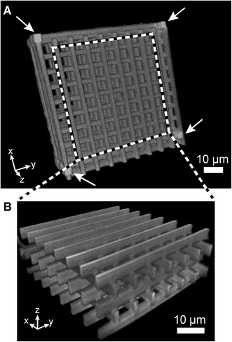 | ||
| Fig. 3 Confocal fluorescence microscopy of a freestanding autoflourescent woodpile structure on a glass cover slip with pore sizes of 8 × 8 μm in the x, y and z directions. (A) 3D reconstruction of the woodpile construct, confirming a porous 3D structure. Support pillars and beams were added at the corners and around the edges of the structure (pillars marked by white arrows). (B) Reconstruction of the center volume outlined in A. | ||
The woodpile writing process was optimized in an open system prior to in-chip fabrication due to easier access for structural characterization by confocal optical microscopy and electron microscopy. All constructs had outer dimensions of W × L × H = 100 μm × 100 μm × 70 μm produced on glass cover slips as substrates. Polymerization of a free-floating polymer wire in liquid resin was problematic since convective flow resulted in the wire floating away before its neighboring wire could be written. Thus, at least the endpoints of all polymerized wires must be anchored to a solid material. The fabrication of free-standing constructs using the top-to-bottom approach called for the introduction of support pillars and beams as anchoring objects, as shown in Fig. 3 with and without the supports. The support pillars were fabricated bottom-to-top to ensure anchoring to the cover slip surface before initiating polymerization of the targeted woodpile construct. A substantial power loss was observed at larger writing depths which could be compensated by reducing the writing speed from 1200 μm s−1 at the bottommost layer to 400 μm s−1 at the topmost layer (70 μm writing depth). The spatial separation of neighboring written wires directly affects the writing time. Center-to-center spacings of 250 nm and 1300 nm in the lateral and vertical dimensions, respectively, were found to minimize writing time while maintaining structural integrity.
The use of a lower magnification objective will increase the voxel volume (formally the two-photon point spread function) and might lead to higher volumetric writing speeds (μm3 s−1). However, the larger voxel volume also reduces the photon density resulting in a strong decrease in two-photon initiated processes. We explored this experimentally using either a 100×/1.4 NA or a 20×/0.5 NA objective and found the required reduction in writing speed at lower magnification to result in largely equal volumetric writing speeds using either objective. The lower magnification objective with a lower numerical aperture will have a substantially elongated voxel in the axial direction, leading to poorer vertical resolution.20,32 Consequently, a 100×/1.4 NA objective was used for the fabrication of all free-standing and in-chip constructs.
In-chip cell migration constructs
Most microfluidic chips designed for in-channel high-resolution optical microscopy can be used as substrates for in-chip 2PP fabrication. The thin bottom layer and the two reservoirs situated next to the channel in the ibidi chip is a particularly favorable design (see Fig. 1). The two reservoirs with a total volume of 130 μL in close proximity to a total channel volume of ≈1 μL facilitate fast diffusion-based development due to a very short diffusion distance of only 0.5 mm. Development times are further reduced by pressure-driven and thermal convection effects during filling and emptying of the reservoirs. In terms of material economics, the closed microchannel system uses very small volumes (few μL) of costly resins and optional biomolecular additives compared to open systems. For chemotaxis analysis, the closed chip system can sustain a controlled linear concentration gradient in solution for up to 48 h28 with better control of the observed gradient than in previously reported open systems written by 2PP.24,25The chemoattractant concentration gradient is established in the middle-channel section of dimensions W × L × H = 1 mm × 2 mm × 70 μm. Microstructured constructs of that size would take several days to produce using the available combination of resin and 2PP system. We chose to reduce the writing time by fabricating a construct of smaller outer dimensions (W × L × H = 100 μm × 300 μm × 70 μm) in the middle of the channel. The minimum construct dimensions were given by three requirements: (a) a substantial number of cells should traverse the porous construct instead of migrating around the construct (minimum length); (b) no cells should be able to sense both ends of the construct with their dendrites simultaneously (minimum width); (c) cells should not be able to migrate above or below the construct (full channel height). The biological relevance of migration analysis constructs with widths on the 100 μm length scale is supported by a recent publication showing oriented motion of murine dendritic cells only within the nearest 100–150 μm of chemokine-secreting lymphatic vessels.33 Ideally, all cells should be forced to migrate through the construct. We tried to achieve this by a “mix-and-match” combination of 2PP fabrication of the 3D microstructured construct followed by conventional 2D-patterned exposure through a shadow mask in a mask aligner to polymerize the bulk barriers leading up to the construct. The process and the resulting in-chip structures are presented in the ESI† Fig. S1. The fabrication procedure was successful, but the bulk structures resulted in substantial cytotoxicity that prevented reliable migration studies. We did not further explore the use of bulk barriers since the cell analysis could be performed with statistical significance on the fraction of cells migrating through the construct in the absence of bulk barriers.
Complete development of in-channel woodpile constructs was verified by fluorescence microscopy. A CO2 laser (FH Flyer, Synrad, Mukilteo, WA) was employed for sectioning a chip next to the woodpile construct to provide optical access. The chip had already been used for cell migration analysis followed by regeneration (collagen degradation) by collagenase treatment. Fig. 4 shows fluorescence micrographs of an in-channel woodpile construct in front view and in bottom view and confirms the presence of a continuous porous structure from channel top to bottom.
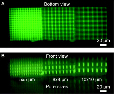 | ||
| Fig. 4 Fluorescence micrograph of a woodpile construct in an ibidi channel shown in (A) bottom view and (B) front view after cell analysis and regeneration with collagenase. Each construct consists of three 100 × 100 × 70 μm3 volumes with 5 × 5 μm, 8 × 8 μm, and 10 × 10 μm pore sizes, respectively. A reflection in the channel bottom is seen in the side view image. The construct microstructure is found to sustain multiple cell loading, cell analysis, and regeneration cycles without observable degradation. | ||
Cytotoxicity is a well-known issue of photopolymerized materials. We compared the metabolic activity of dendritic cells cultured on polymerized slabs of IP-L resin to polymerized slabs of a widely used poly(ethylene glycol) diacrylate resin.34 Both materials induced similar, slightly reduced metabolic activity compared to a reference cell culture surface of tissue culture grade polystyrene (TCPS) (ESI† Fig. S2). The cytotoxicity of the in-chip written IP-L constructs was not evaluated directly. However, the efficient washing process via the chip reservoirs is expected to remove unreacted macromers and photoinitiators to a similar extent as found for the IP-L slabs. This assumption is supported by our observation of indistinguishable DC migration behavior (speed and directionality) through collagen gel in channels with or without a fabricated IP-L construct (data not shown).
Directed in-chip cell migration
The IP-L woodpile constructs were tested for their ability to allow directed DC transmigration in a concentration gradient of the chemokine CCL21 in the construct, hereafter termed “front-to-back” migration. We designed woodpile constructs with square pore sizes of 5 × 5 μm, 8 × 8 μm, 10 × 10 μm, and 15 × 15 μm to evaluate the ability of the DCs to migrate or squeeze through cell-sized passage ways (Fig. 3 and 4). These dimensions were chosen based on former work reporting in vivo pore sizes of 1–20 μm in mouse connective tissue and 2–10 μm in human dermis.17 Collagen was introduced into the construct pores to provide a biological environment supporting migration while still permitting formation of the chemokine gradient, as demonstrated in former chemotaxis studies using similar minimal channel cross-sections (3 μm × 10 μm versus 5 μm × 5 μm in this work).11 Migration through the 5 × 5 μm pores was rarely seen and thus not included in the statistical analysis of the migration pathways. The inability of DCs to pass the 5 × 5 μm pores despite the presence of a chemokine gradient is interesting, since we have recently successfully used conventional Transwell migration assays with circular pore diameters of 5 μm to study other aspects of DC migration potential.35 The main topological difference is the much smaller thickness (width) of the 10 μm thick Transwell membrane that allows DC dendrites of lengths >50 μm to explore the highest and lowest chemokine concentrations simultaneously, effectively presenting a very steep concentration gradient. In this aspect, our 100 μm wide constructs with a definable gradient slope likely resemble the in vivo microenvironment of the DCs more closely.33In further migration experiments, we only used woodpile constructs with pore sizes of 8 × 8, 10 × 10, and 15 × 15 μm, respectively. DC migration was analyzed by manual inspection of time-lapse image sequences to determine the number of lateral turns (in bottom view) performed by each cell inside woodpile structures of different pore sizes. A lateral turn requires concomitant vertical translocations due to the woodpile topology, thereby revealing full 3D cell motion. Directed cell migration analysis requires a stable CCL21 concentration gradient that is established by diffusion in the full channel width within hours, and cells need to migrate from the sink reservoir where they are seeded. Consequently, the tracking of cells was only started once significant migration was observed within the channel region (typically within 4 hours). The introduction of a microporous construct might delay gradient formation within the construct. As discussed in the ESI,† the microscopic pore dimensions, the large porosity of the woodpile topology (>0.68), and the high constrictivity factor (estimated to be 0.9)36 give a reduction in the effective CCL21 diffusion constant by <2. Thus, the additional time involved in establishing a stable gradient within the 100 μm wide construct will be insignificant compared to the time for forming the full gradient across the 1 mm wide channel.
In general, the DCs continue their migration path after entering the construct and do not seem to have problems detecting the concentration gradient within the construct. Fig. 5 shows microscopy snapshots at different time points of two DCs crossing a 15 × 15 μm pore size woodpile structure. Both cells initially probe two neighboring channel structures with their dendrites before deciding to traverse one of the channels without performing any turns inside the construct. An equivalent behavior has been observed for neutrophils encountering bifurcations in a straight microchannel system.37 Movies of the time-lapse series are available in image-processed and unprocessed versions (ESI† Movies 1 and 2). Fig. 6 summarizes the observed difference in migration behavior. Cells migrating through the smaller pore dimensions (8 × 8 and 10 × 10 μm) have a significantly higher probability of making at least one turn than cells migrating through the largest pores (15 × 15 μm). In the latter geometry, the majority of DCs move straight through the porous construct, while most cells make at least one turn on their passage through the smallest pore size structures. ESI† Fig. S3 shows a detailed analysis of the number of turns made (0, 1–2, 3–4, or 5–6 turns, respectively) as a function of pore size, with a clear trend towards more turns occurring in smaller pores. The results indicate that the cells are more prone to seek alternative paths when confined to smaller cross-sectional areas in a tighter woodpile.
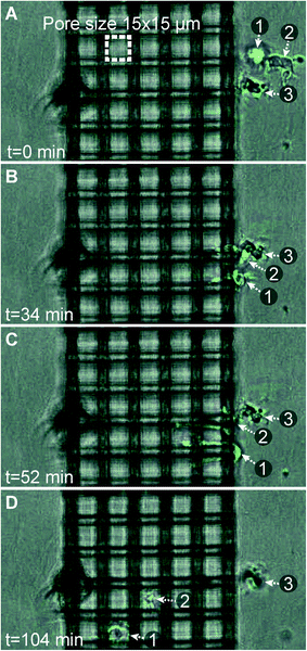 | ||
| Fig. 5 Phase contrast microscopy snapshots (bottom view) showing two dendritic cells (labeled “1” and “2”) migrating inside a 15 × 15 μm pore size woodpile construct. Both cells probe neighboring channels in (B) and (C), before deciding on a channel to migrate through in (D). The cell outlines have been highlighted by the use of image processing in ImageJ. | ||
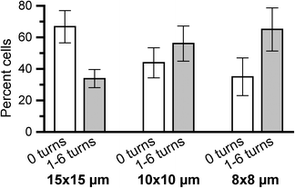 | ||
| Fig. 6 Comparison of the fraction of cells moving straight through a woodpile construct to cells taking 1 or more turns as a function of the construct pore size. Significantly more cells turn as they migrate through 8 × 8 μm pore constructs than through 15 × 15 μm pore constructs (p = 0.033). Error bars show the standard error of the mean (n ≥ 7). | ||
The free-form 2PP process allows for the introduction of barriers to cell migration at arbitrary locations. We explored this design freedom to measure the ability of DCs to navigate in 3D maze structures. The basic woodpile topology permits direct cell migration from the front to the back of the construct, as was most commonly observed for the 15 × 15 μm pores (Fig. 6). If the cell wants to turn, it will need to change its vertical level beforehand to reach a channel in the perpendicular orientation. By blocking the straight front-to-back channels by one additional photopolymerized barrier per channel at alternating positions in neighboring channels, we force all migrating cells to perform at least two half spiral turns in 3D. Fig. 7A shows a computer rendition of the targeted structure in perspective and in side view. The basic woodpile structure is shown in gray while the additional barriers present in all three layers with front-to-back pathways are shown in dark green. The side view shows the barrier-free passageways for cells in the three layers with sideway channels. The outer dimensions of the construct are increased to W × L × H = 200 μm × 400 μm × 70 μm to provide a longer and more detailed analysis of the migration path of the individual cells. The detailed DC migration analysis through the basic woodpile structure indicated a higher fraction of cells making multiple turns through the 10 × 10 μm porous construct than either 15 × 15 μm or 8 × 8 μm pores (ESI† Fig. S3). Consequently, we selected the 10 × 10 pore size for the higher complexity construct. Fig. 7B shows a confocal fluorescence micrograph of one of the layers containing extra barriers in the final in-chip-produced construct. Cross-sectional views through one set of the additional barriers show blockage of every second front-to-back channel, while a cross-section through the other set of barriers would show blockage of the remaining front-to-back channels.
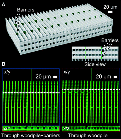 | ||
| Fig. 7 A higher complexity 3D cell migration construct. (A) Schematic of the construct highlighting in green the additional barriers introduced to obstruct cell migration straight through the construct (from front to back). Inset: construct in side view showing the free passageways in the perpendicular direction. (B) Confocal fluorescence micrograph of the construct fabricated by 2PP, focusing on the lower three layers. Left: orthogonal slice through the barriers (along the dashed line in the x/y projection) showing blockage of every second front-to-back channel in the x/z projection. Right: slice through the basic woodpile showing all channels are open at these locations. | ||
DCs were seeded next to the complex constructs using the same procedure as for basic woodpile constructs. The resulting time-lapse sequences are available in image-processed and unprocessed formats as ESI† Movies 3 and 4, respectively. In general, DCs efficiently found their way through the construct, showing their detection of the chemotactic concentration gradient even in a more complex topology calling for intermittent migration perpendicular to the concentration gradient. Fig. 8 compares the results from the manual cell tracking in 10 × 10 μm pore woodpiles with or without additional barrier structures. The comparison shows a clear trend for DCs to take many more turns in constructs with additional barriers, also beyond the minimum 2 turns required to traverse the construct from front to back. We observed multiple possible pathways being probed by both DCs in Fig. 5 with very long straight dendrites (up to 70 μm in length, see ESI† Movies 1 and 2) being extended into the construct channels prior to deciding on a channel for transmigration. The presence of additional barriers prevents straight extension of probing dendrites and may thus result in less persistent cell motion either due to differences in signal processing or due to the need for repeated cytoskeletal rearrangements. This is most likely also the case in the less organized in vivo extracellular microenvironment.
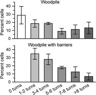 | ||
| Fig. 8 Fraction of DCs making specific numbers of turns inside an in-chip woodpile construct with 10 × 10 μm pores without (top) or with (bottom) additional barriers as shown in Fig. 7. Note that cells by design of the construct must make at least two turns to pass the barriers. Error bars show the standard error of the mean (n = 3). | ||
Recent work explored the correlation of average pore sizes in random 3D collagen gel networks to the resulting chemotaxis speeds of different cell types ranging from small neutrophils over intermediate-sized T blasts to large cancer cells.4 The fibrillar collagen gel pore size was varied via the concentration and type of collagen used to reflect the variability of fiber widths and interfibrillar spacings observed in connective tissue in vivo.17 The authors observed a strong correlation between the average pore size and migration speed for all three cell types correlating to the size and deformability of their respective nuclei. However, the measured pore sizes spanned more than a factor of 3 for the less dense networks (average pore size >15 μm2), which likely contributed to the broad range of measured cell migration speeds. In a complementary approach, the motion of the DCs was accurately confined within straight PDMS microchannels at a substrate surface, thus bordering 2D and 3D migration.14 The latter study provided a highly reproducible porous environment for cell migration at the cost of a simplified model of a connected 3D pore network of spatially varying complexity. The synthetic in-chip-fabricated 3D constructs presented here ideally capture the best of both analytical approaches by providing an accurate structural definition and allowing for arbitrary variations in 3D connectivity, with or without the added ultrastructure of fibrillar collagen. We observed DC migration speeds of 5–6 μm min−1 in the unbranched, straight microchannels filled with fibrillar collagen (data not shown) in good agreement with former work using protein-coated but unfilled channels.14 However, the effective migration speed was significantly reduced upon the introduction of branching or barriers in the channel systems due to repeated directional decision processes by the cell when encountering an obstacle parallel (woodpile wall at the construct entrance) or perpendicular (barrier) to its direction of motion. This is in agreement with in vivo migration studies showing slower migration speeds of approx. 2 μm min−1 of DCs migrating towards lymph nodes.33
Chip regeneration compensates for higher fabrication costs
Two-photon polymerization is a serial and time-consuming fabrication process which is not well suited for affordable single-use systems. Thanks to the easy liquid exchange and sink/source design of the ibidi chip system, the collagenase treatment introduced here thoroughly rinses the chip of collagen residues and prepares the construct for repeated experiments. The effect of the collagenase treatment is observed in Fig. 4 where there is no sign of collagen left on the construct after multiple experiments. The hard IP-L resin creates a tough structure where the pores are still intact and the structural integrity of the construct is not compromised by the treatment. The collagenase regeneration drastically reduces the cost of multiple experiments not only for this system but also for many others that utilize collagen in confined spaces. The only requirement is easy liquid exchange in the system.Conclusions
In-chip two-photon polymerization of 3D microporous constructs combines the best of two chip fabrication approaches: (1) fast low-definition 2D macroscopic scale production of channel structures compatible with conventional optical analysis and standardized connectors interfacing to the surroundings; (2) slower high-definition 3D fabrication of small volume application-specific components. Direct in-chip fabrication obviates the need for subsequent chip-bonding processes that often require extensive optimization to avoid leakage and may easily damage the fragile micro- or nanostructures present at the chip surfaces to be bonded. The 2PP process provides accurate control of both the pore size and the topology experienced by the migrating cells in a material that does not appear to affect their migratory behavior. The source/drain design of the ibidi chip gives complete control of the concentration and thus the steepness of the chemokine gradient. Combining these aspects with easy visualization and cell tracking through the thin bottom adds up to a very versatile and easy to use migration analysis system. The collagenase regeneration procedure strongly reduces the cost per experiment and thus compensates for the higher expense of 2PP fabrication. We foresee that our in-chip-designed constructs can be employed both for optimizing cell processing conditions to maximize in vivo chemotaxis of DCs, an essential requirement for effective DC-based immunotherapy35,38 and for validating the migratory potential of each patient's cells in immunotherapy.Acknowledgements
We acknowledge financial support from the Danish Council for Independent Research, Technology and Production Sciences, grant# 09-070021.Notes and references
- E. Cukierman, R. Pankov, D. Stevens and K. Yamada, Science, 2001, 294, 1708–1712 CrossRef CAS PubMed.
- P. Friedl and B. Weigelin, Nat. Immunol., 2008, 9, 960–969 CrossRef CAS PubMed.
- T. Laemmermann and M. Sixt, Curr. Opin. Cell Biol., 2009, 21, 636–644 CrossRef CAS PubMed.
- K. Wolf, M. Te Lindert, M. Krause, S. Alexander, J. Te Riet, A. L. Willis, R. M. Hoffman, C. G. Figdor, S. J. Weiss and P. Friedl, J. Cell Biol., 2013, 201, 1069–1084 CAS.
- T. Laemmermann, B. L. Bader, S. J. Monkley, T. Worbs, R. Wedlich-Soeldner, K. Hirsch, M. Keller, R. Foerster, D. R. Critchley, R. Faessler and M. Sixt, Nature, 2008, 453, 51–55 CrossRef CAS PubMed.
- H. Kim and S. R. Peyton, Integr. Biol., 2012, 4, 37–52 RSC.
- V. V. Abhyankar, M. W. Toepke, C. L. Cortesio, M. A. Lokuta, A. Huttenlocher and D. J. Beebe, Lab Chip, 2008, 8, 1507–1515 RSC.
- A. N. Stachowiak and D. J. Irvine, J. Biomed. Mater. Res., Part A, 2008, 85A, 815–828 CrossRef CAS PubMed.
- S. R. Peyton, Z. I. Kalcioglu, J. C. Cohen, A. P. Runkle, K. J. Van Vliet, D. A. Lauffenburger and L. G. Griffith, Biotechnol. Bioeng., 2011, 108, 1181–1193 CrossRef CAS PubMed.
- C. Decaestecker, O. Debeir, P. Van Ham and R. Kiss, Med. Res. Rev., 2007, 27, 149–176 CrossRef CAS PubMed.
- D. Irimia, G. Charras, N. Agrawal, T. Mitchison and M. Toner, Lab Chip, 2007, 7, 1783–1790 RSC.
- D. Irimia and M. Toner, Integr. Biol., 2009, 1, 506–512 RSC.
- J. Jacobelli, R. S. Friedman, M. A. Conti, A. Lennon-Dumenil, M. Piel, C. M. Sorensen, R. S. Adelstein and M. F. Krummel, Nat. Immunol., 2010, 11, 953–961 CrossRef CAS PubMed.
- G. Faure-Andre, P. Vargas, M. Yuseff, M. Heuze, J. Diaz, D. Lankar, V. Steri, J. Manry, S. Hugues, F. Vascotto, J. Boulanger, G. Raposo, M. Bono, M. Rosemblatt, M. Piel and A. Lennon-Dumenil, Science, 2008, 322, 1705–1710 CrossRef CAS PubMed.
- Z. Tong, E. M. Balzer, M. R. Dallas, W. Hung, K. J. Stebe and K. Konstantopoulos, PLoS One, 2012, 7, e29211 CAS.
- M. van der Rest and R. Garrone, FASEB J., 1991, 5, 2814–2823 CAS.
- K. Wolf, S. Alexander, V. Schacht, L. M. Coussens, U. H. von Andrian, J. van Rheenen, E. Deryugina and P. Friedl, Semin. Cell Dev. Biol., 2009, 20, 931–941 CrossRef CAS PubMed.
- O. Sarig-Nadir, N. Livnat, R. Zajdman, S. Shoham and D. Seliktar, Biophys. J., 2009, 96, 4743–4752 CrossRef CAS PubMed.
- M. W. Tibbitt, A. M. Kloxin, K. U. Dyamenahalli and K. S. Anseth, Soft Matter, 2010, 6, 5100–5108 RSC.
- S. Maruo, O. Nakamura and S. Kawata, Opt. Lett., 1997, 22, 132–134 CrossRef CAS.
- J. Serbin, A. Egbert, A. Ostendorf, B. Chichkov, R. Houbertz, G. Domann, J. Schulz, C. Cronauer, L. Frohlich and M. Popall, Opt. Lett., 2003, 28, 301–303 CrossRef CAS.
- C. N. LaFratta, J. T. Fourkas, T. Baldacchini and R. A. Farrer, Angew. Chem., Int. Ed., 2007, 46, 6238–6258 CrossRef CAS PubMed.
- A. M. Greiner, B. Richter and M. Bastmeyer, Macromol. Biosci., 2012, 12, 1301–1314 CrossRef CAS PubMed.
- P. Tayalia, C. R. Mendonca, T. Baldacchini, D. J. Mooney and E. Mazur, Adv. Mater., 2008, 20, 4494–4498 CrossRef CAS.
- P. Tayalia, E. Mazur and D. J. Mooney, Biomaterials, 2011, 32, 2634–2641 CrossRef CAS PubMed.
- L. Amato, Y. Gu, N. Bellini, S. M. Eaton, G. Cerullo and R. Osellame, Lab Chip, 2012, 12, 1135–1142 RSC.
- M. Iosin, T. Scheul, C. Nizak, O. Stephan, S. Astilean and P. Baldeck, Microfluid. Nanofluid., 2011, 10, 685–690 CrossRef CAS.
- ibidi GmbH, http://ibidi.com/applications/chemotaxis/gradient-stability/, 2013.
- W. S. Rasband, ImageJ, U.S. National Institutes of Health, Bethesda, Maryland, USA, http://imagej.nih.gov/ij/, 1997–2012 Search PubMed.
- H. Jonuleit, U. Kühn, G. Müller, K. Steinbrink, L. Paragnik, E. Schmitt, J. Knop and A. H. Enk, Eur. J. Immunol., 1997, 27, 3135–3142 CrossRef CAS PubMed.
- P. Thevenaz, U. E. Ruttimann and M. Unser, IEEE Trans. Image Process., 1998, 7, 27–41 CrossRef CAS PubMed.
- W. Zipfel, R. Williams and W. Webb, Nat. Biotechnol., 2003, 21, 1368–1376 CrossRef PubMed.
- M. Weber, R. Hauschild, J. Schwarz, C. Moussion, I. de Vries, D. F. Legler, S. A. Luther, T. Bollenbach and M. Sixt, Science, 2013, 339, 328–332 CrossRef CAS PubMed.
- C. Williams, A. Malik, T. Kim, P. Manson and J. Elisseeff, Biomaterials, 2005, 26, 1211–1218 CrossRef CAS PubMed.
- M. Hansen, G. M. Hjorto, M. Donia, O. Met, N. B. Larsen, M. H. Andersen, P. thor Straten and I. M. Svane, Vaccine, 2013, 31, 639–646 CrossRef CAS PubMed.
- J. van Brakel and P. M. Heertjes, Int. J. Heat Mass Transfer, 1974, 17, 1093–1103 CrossRef.
- V. Ambravaneswaran, I. Y. Wong, A. J. Aranyosi, M. Toner and D. Irimia, Integr. Biol., 2010, 2, 639–647 RSC.
- P. Verdijk, E. H. J. G. Aarntzen, C. J. A. Punt, I. J. M. de Vries and C. G. Figdor, Expert Opin. Biol. Ther., 2008, 8(7), 865–874 CrossRef CAS PubMed.
Footnote |
| † Electronic supplementary information (ESI) available: Fabrication of solid barriers; cytotoxicity analysis of photopolymers; detailed cell migration analysis; calculated diffusion through microporous constructs; time-lapse movies of migrating dendritic cells. See DOI: 10.1039/c3lc50930c |
| This journal is © The Royal Society of Chemistry 2013 |
