 Open Access Article
Creative Commons Attribution 3.0 Unported Licence
A perspective: carbon nanotube macro-films for energy storage
Zeyuan
Cao
b and
Bingqing (B. Q.)
Wei
*ab
aState Key Laboratory of Solidification Processing and School of Materials Science and Engineering, Northwestern Polytechnical University, Xi'an 710072, China
bDepartment of Mechanical Engineering, University of Delaware, 126 Spencer Lab, Newark, DE 19716, USA. E-mail: weib@udel.edu; Fax: +1-(302)831-3619; Tel: +1-(302)831-6438
First published on 17th September 2013
Abstract
The ever-increasing demand of electricity storage is a growing challenge among a broad range of renewable energy sources. The development of high-energy storage devices has been one of the most important research areas in modern days. In particular, rechargeable batteries and electrochemical capacitors are recognized as the primary power sources for applications from portable electronic devices to electric vehicles. In order to power the emerging flexible/stretchable electronics, power sources themselves must be able to accommodate high levels of deformation and stretchability in addition to high energy and power density, light weight, miniaturization in size, safety qualification, and other significant characteristics. Utilizing carbon nanotubes (CNTs) for various energy storage applications such as electrodes in lithium ion batteries and supercapacitors, are under close scrutiny because of the promising electrochemical performance in addition to their extraordinary tensile strength and flexibility, ultrahigh surface area, and excellent thermal and electrical conductivity. Recently, there has been growing interest in investigating CNT macro-films with large-scale organized nanostructures of desired shape and form and unique and enhanced properties: integrity and stability to realize the scaled-up energy storage devices. In this perspective, research efforts in assembling 2-D CNT macro-films using a chemical vapor deposition method and their applications for different energy storage devices including stretchable supercapacitors, supercapacitors working under extreme conditions such as high temperature and high pressure, and lithium–ion batteries are discussed. In details, this paper provides an original overview involving the effect of compressive stress on the electrochemical behavior of flexible supercapacitors assembled with CNT macro-film electrodes and electrolytes with different anions and cations; the demonstration of the dynamic and galvanic stability of stretchable supercapacitor using buckled CNT macro-films by an in situ dynamic electrochemical testing method; the understandings on the self-discharge mechanisms of CNT macrofilm-based supercapacitors from both electrode and electrolyte aspects; and the investigation of the electrochemical properties of the tandem structure of active materials (e.g. thin porous silicon film and CuO) with CNT macro-films acting as a flexible and adhesive layer between the active layers and current collectors for lithium–ion batteries. Future research on CNT macro-films-based lithium–sulfur batteries and lithium–air batteries is also discussed.
Broader contextEnergy storage devices (supercapacitors and Li–ion batteries) with high power and energy density, reliable robustness working in complex conditions such as high temperature and compression as well as flexibility/stretchability attracted more attention for the growing demanding of portable electronics, electric vehicles and stationary electrical grids. Self-assembled carbon nanotube macro-films with tailored electrical and mechanical properties can be configured into 2D or 3D (stacking multiple layers) structures, therefore have the potential to develop large-area planar or bulk porous electrodes with superior performance than traditional materials for energy storage applications. Single-walled carbon nanotube (SWNT) macro-film-based energy storage devices have been intensively studied recently, and such research efforts are still growing. An in-depth review of these technologies is very significant to related fields at present time. This perspective article focuses on unique applications enabled by pure or hybrid SWNT films including stretchable supercapacitors, pseudocapacitors, and Li–ion batteries based on particularly designed SWNT with buckled structures or SWNT composites. In addition, key characteristics of SWNT macro-films with respect to practical applications in high temperature and stress conditions are discussed, and self-discharge mechanism is explored and analyzed. Finally, future directions in Li–sulfur and Li–air batteries are outlined. |
1. Introduction
As concern grows over fossil fuel usage and its ever-aggravating impact on global warming, environments, and the crisis of natural resource depletion, research and development on energy in the 21st century is focused on a broad range of renewable energy sources (e.g. solar and wind). In addition to the challenge of harnessing the renewable clean energy sources to generate electricity, electricity storage, i.e. the administrable ability to capture, store, and deliver the generated power based on practical need, becomes a dominant science and technology issue with the increasing productivity of electricity generation and the demand of portable electronics, electric vehicles, and stationary electrical grids.Currently, the development of high-energy and high-power energy storage devices focuses on two major types of power sources: rechargeable lithium–ion batteries (LIBs) and electrochemical capacitors (also known as supercapacitors or ultracapacitors) because of their complementary advantageous performance in energy density and power density aspects. From the Ragone plot (Fig. 1)1 with specific energy versus specific power of various energy storage devices, LIBs overmatch supercapacitors in terms of the energy density (120–200 W h kg−1),2,3 but have a lower power density in the range from 0.4 to 3 kW kg−1 and a shorter cycle life (<1000 cycles).4
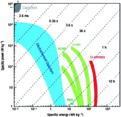 | ||
| Fig. 1 Ragone plot for various electrochemical energy storage devices. Reproduced with permission from ref. 1 ©2008, Macmillan Publishers Limited. | ||
In comparison with LIBs, typical supercapacitors, including electric double layer capacitors (EDLCs) and pseudocapacitors, have a lower energy density of about 5–8 W h kg−1 but a higher power density (5 to 30 kW kg−1), owing to the ultrafast charge–discharge capability for a single cycle. The supercapacitors also have the advantage of a longer life, exhibiting an extremely high cyclic stability of more than 100![[thin space (1/6-em)]](https://www.rsc.org/images/entities/char_2009.gif) 000 cycles.1,5,6 Nevertheless, supercapacitors suffer from rapid self-discharge (SDC) which remains a significant challenge to limit their energy retention.7,8 Thus, it is necessary to understand the SDC mechanisms associated with specific electrodes and electrolytes in order to realize the tunable energy retention of supercapacitors.
000 cycles.1,5,6 Nevertheless, supercapacitors suffer from rapid self-discharge (SDC) which remains a significant challenge to limit their energy retention.7,8 Thus, it is necessary to understand the SDC mechanisms associated with specific electrodes and electrolytes in order to realize the tunable energy retention of supercapacitors.
However, LIBs and supercapacitors are still insufficient for the long term demand of transport and electricity storage (electric vehicles and smart grids). It promotes new technologies for electrochemical cells with different working mechanisms from LIBs. Lithium–sulfur (Li–S) and lithium–air (Li–air) batteries are two promising battery systems with extremely high theoretical specific energy of 2567 W h kg−1 and 3505 W h kg−1, respectively9,10 for the future.
In addition to having a higher power density and higher energy density, as well as long cyclic performance, the future aim for electrochemical energy storage devices need to also possess reliable robustness when working in various specific and even extreme environments, e.g. with temperatures ranging from −40 to 160 °C,11 under ultra-low and high pressure, and for special use in flexible/stretchable electronic devices when stretching to high levels of deformation (>100%),12 to ensure the low maintenance level for future consumer, industrial, military, and space applications.
Carbon-based nanomaterials have structural diversity in different forms such as activated carbons,13 templated carbons,14 carbide-derived carbons,15 activated carbon fabrics,16 carbon fibers,17 carbon aerogels,18 carbon nanotubes (CNTs),19,20 carbon nanohorns,21 carbon onions,22 and the emerging graphene23–25 or graphene composite26–28 in recent research. They have been widely used and extensively studied as electrode materials, due to their high conductivity, high surface area (up to 2000 m2 g−1),29 excellent anti-corrosion property, high temperature stability, controllable porous structure, compatibility in composite materials, and relatively low cost.30 They are currently incorporated into such energy storage devices as electro-conductive additives,31 ideal substrate for active materials,32 electrocatalysts,33 and intercalation hosts.34 Compared with other carbon nanostructured materials and regular CNTs in a powder form, CNT macro-films with controllable web-like networks that are self-assembled by CNTs as building units show unique and superior mechanical robustness, thermal stability, and electrical conductivity (10![[thin space (1/6-em)]](https://www.rsc.org/images/entities/char_2009.gif) 000–100
000–100![[thin space (1/6-em)]](https://www.rsc.org/images/entities/char_2009.gif) 000 S cm−1) in a more stable and flexible integrity which is ideal for energy storage device applications.35 In this article, we are primarily concerned with CNT macro-film-based energy storage devices and summarize a series of works on supercapacitors and LIBs based on single-walled carbon nanotube (SWNT) macro-films with the corresponding investigation of the unique characteristics of the films as electrodes in the following sections:
000 S cm−1) in a more stable and flexible integrity which is ideal for energy storage device applications.35 In this article, we are primarily concerned with CNT macro-film-based energy storage devices and summarize a series of works on supercapacitors and LIBs based on single-walled carbon nanotube (SWNT) macro-films with the corresponding investigation of the unique characteristics of the films as electrodes in the following sections:
1 stretchable supercapacitors using the buckled SWNT macro-films
2 electrochemical behavior of SWNT macro-film-based supercapacitors under compressive stress
3 pseudocapacitors using SWNT/MnO2 hybrid macro-films
4 effect of temperature on SWNT macro-film-based supercapacitors
5 self-discharge process of SWNT macro-film-based supercapacitors
6 lithium–ion batteries with the sandwiched structure of SWNT/CuxOy/Cu composites as anode
7 lithium–ion batteries with the tandem structure of porous Si–SWNT composites as anode
We also envision and provide perspectives towards the SWNT macro-films to be employed in future work on Li–S and Li–air batteries.
2. SWNT macro-films
2.1. Fabrication of SWNT macro-films
Large-scale fabrication of SWNT films with homogeneous and controllable size and porous structure could be achieved by various approaches including post-processing methods: LB technique,36 vacuum filtration,37 drying drop,38 and direct synthesis: arc-discharge39 and chemical vapor deposition (CVD).40 Although the multi-step post-treatment methods are usually capable of precisely controlling the desired orientation, morphology, and pore sizes of the SWNT films, the complicated processing techniques and time-consuming shortcomings extremely limit the large yield of the products in practical applications. Therefore, a more direct, simple and cost-effective way is needed and was successfully developed.41 The typical synthesis process is to use the solid volatile mixture of ferrocene–sulfur powders (atomic ratio Fe![[thin space (1/6-em)]](https://www.rsc.org/images/entities/char_2009.gif) :
:![[thin space (1/6-em)]](https://www.rsc.org/images/entities/char_2009.gif) S = 10
S = 10![[thin space (1/6-em)]](https://www.rsc.org/images/entities/char_2009.gif) :
:![[thin space (1/6-em)]](https://www.rsc.org/images/entities/char_2009.gif) 1) as precursors by a modified floating CVD method. It has two separate phases: deposition and growth. During the deposition, the ferrocene with a relatively low sublimation point (∼100 °C) is introduced with the carrier gas flow of argon (200 mL min−1) into the central reaction zone of the furnace from the inlet of a ceramic tube. The ferrocene then starts pyrolysis at a high temperature to generate a carbon source and iron catalyst. The growth was carried out at 1150 °C with a mixed gas flow of argon (1500 mL min−1) and hydrogen (150 mL min−1). Sulfur acts as an additive to promote SWNT growth as well as to enhance the growth rate of SWNTs. It was widely recognized that sulfur is predominant in controlling the wall number of CNTs. It is found that large-area SWNT macro-films with uniformity (randomly homogeneous entanglement of SWNT bundles) and conformability (distribution of the nanotube diameter ranges from 0.8 to 1.3 nm as shown in Fig. 2) could be collected from the entire tube with a large diameter. This is the result of a reverse gas flow generated from the central hot zone to the cold ends due to the pressure difference between them. The thickness of the films can be adjusted by controlling the amount of the precursor mixtures, substrate position in the tube, and reaction time.
1) as precursors by a modified floating CVD method. It has two separate phases: deposition and growth. During the deposition, the ferrocene with a relatively low sublimation point (∼100 °C) is introduced with the carrier gas flow of argon (200 mL min−1) into the central reaction zone of the furnace from the inlet of a ceramic tube. The ferrocene then starts pyrolysis at a high temperature to generate a carbon source and iron catalyst. The growth was carried out at 1150 °C with a mixed gas flow of argon (1500 mL min−1) and hydrogen (150 mL min−1). Sulfur acts as an additive to promote SWNT growth as well as to enhance the growth rate of SWNTs. It was widely recognized that sulfur is predominant in controlling the wall number of CNTs. It is found that large-area SWNT macro-films with uniformity (randomly homogeneous entanglement of SWNT bundles) and conformability (distribution of the nanotube diameter ranges from 0.8 to 1.3 nm as shown in Fig. 2) could be collected from the entire tube with a large diameter. This is the result of a reverse gas flow generated from the central hot zone to the cold ends due to the pressure difference between them. The thickness of the films can be adjusted by controlling the amount of the precursor mixtures, substrate position in the tube, and reaction time.
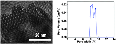 | ||
| Fig. 2 Distribution of the nanotube diameter from SEM image (left) and BET measurement (right). | ||
This method to deposit SWNT macro-films directly has three advantages compared with other direct synthesis. First, the precursor system only contains two solid state components and no liquid or additional carbon source (e.g. methane,42 hexane,43 and xylene44) and catalysts are required. Second, it demonstrates that the films can be deposited on various flexible substrates from metallic foils (copper, stainless steel, aluminum, nickel etc.) to polymer films which could be placed at both cold ends of the inner tube. Last but not the least, the as-deposited SWNT macro-film with up to 200 cm2 area is easily peeled off from substrates without any damage and could also be transferred to current collectors and further cut into any desired shapes and sizes or maintained in a free-standing form when used as electrodes for electrochemical cells (Fig. 3).
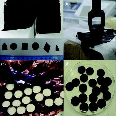 | ||
| Fig. 3 (a) SWNT macro-film on the metal substrates is cut to various shapes. (b) Free-standing SWNT macro-films. (c and d) Disk electrodes punched by SWNT macro-films on Cu foils. | ||
2.2. Unique properties of SWNT macro-films
The as-synthesized SWNT macro-films have a porous structure with large surface area and contain impurities of iron catalysts derived from the pyrolysis of ferrocene and amorphous carbon. These characteristics make them a potential cathode catalyst for Li–air batteries. Meanwhile, the films also exhibit a hydrophobic property on the surface which enables the protection of organic electrolyte and lithium metal as anodes from deterioration by the water vapor in air and consequently will improve the life of cells. Post purification such as heat treatment in air at 450 °C for 0.5–1 h or slight oxidation by immersion in 30% H2O2 solution for 72 h and rinsing with acid (37% HCl) can remove the impurities and transform the initial hydrophobic surface to hydrophilic by increasing hydroxyl, carboxyl, and other functional groups without damaging the integrity of the films. The purified macro-films still hold the porous structures. The presence of oxygen-containing functional groups could enhance the adhesion of the SWNT macro-films with current collectors and be coupled with other active electrode nanomaterials such as MnO2,45 V2O5,46 Fe2O3,47 LiNi0.4Mn0.4Co0.2O2,48 LiFePO4,49 and sulfur50 to form nanocomposites for pseudocapacitors, LIBs, and Li–S batteries. After functionalization (oxidation), the high electrical conductivity of the films is little impacted. The thinnest film (<50 nm) obtained in our lab by using the similar method with tunable growth rate of SWNT still has a sheet resistance of ∼45 Ω □−1 with an optical transparency of as high as 80%. When the films are disassembled into tiny pieces under ultrasound, their intrinsic properties of sticky surface and web-like morphology would maintain, making them a potential binder additive with high conductivity. In addition, SWNT macro-films can be buckled in a periodic wavy form that exhibits excellent stretchability up to 50% pre-strain, and it is also notable that the electrical resistance experienced no remarkable change even under 50% tensile strain. Combination of these unique properties from high flexibility and deformability to superior electrical conductivity, adhesive surface, and the hydrophobic–hydrophilic transformation, awards the SWNT macro-films to open a promising field worth the investigation and research of their potential applications in electrochemistry, especially in energy storage.3. SWNT macro-film-based electrodes for supercapacitors
A typical supercapacitor consists of two electrodes (positive and negative) immersed in electrolyte and a separator that electrically isolates them. According to different operation mechanisms, supercapacitors are classified into two major types: electrical double layer capacitors (EDLCs) and pseudo- or redox-capacitors. The EDLC is charged and discharged by the creation and release of the electrical double layers through the accumulation of electrolyte ions at the electrode/electrolyte interface. In EDLCs, the capacitance is contributed by electrostatic interactions of electron and dielectric materials on interfaces of electrodes and electrolytes and the energy is stored in the double layers (Fig. 4). The double layer capacitance, Cdl, at each electrode interface is given by eqn (1) (ref. 51) | (1) |
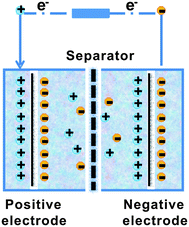 | ||
| Fig. 4 The scheme of electrical double layer capacitors (EDLCs). | ||
Based on the types of electrolyte, the supercapacitors can be mainly divided to aqueous, including acidic solutions such as H2SO4,58 neutral solutions (e.g. Na2SO4 (ref. 59)), and alkali solutions (KOH60), and nonaqueous, including organic solutions such as tetraethylammonium tetrafluoroborate (TEABF4) in polycarbonate (PC),16 and ionic liquids.52 The voltage window of the supercapacitor is determined by the electrolyte. The aqueous supercapacitors usually have a very narrow voltage window as low as about 1.2 V while it can be extended beyond 3 V by switching to an organic electrolyte.
Specific capacitance Cs (Fg−1) is usually considered in order to evaluate and compare the electrode materials for supercapacitors, which is calculated from eqn (2):
 | (2) |
![[C with combining macron]](https://www.rsc.org/images/entities/i_char_0043_0304.gif) s) is calculated according to eqn (3) using CV:8
s) is calculated according to eqn (3) using CV:8 | (3) |
![[C with combining macron]](https://www.rsc.org/images/entities/i_char_0043_0304.gif) s is worked out by GCD measurement from eqn (4):61
s is worked out by GCD measurement from eqn (4):61 | (4) |
From eqn (2), the specific capacitance of the cell is dominated by the smaller one between the specific capacitance of two electrodes. In addition, the electrochemical performance of the supercapacitors is also evaluated in terms of energy density (E) and power density (P) expressed in eqn (5) and (6):8,61
 | (5) |
 | (6) |
3.1. Stretchable supercapacitors based on buckled SWNT macro-films
Stretchable electronics that could offer excellent stretchability responding to large deformation (≫1%)62,63 have attracted considerable attention in very recent years with the emergence of many realistic applications that traditional rigid electronics cannot achieve, such as the wearable photovoltaics,64 sensors,65–67 organic light emitting diode (OLED),68 the electronic imaging ‘eyeball’,69 and etc. To accommodate the need for bending, stretching, compressing, and twisting of these flexible and stretchable electronics, energy storage devices, as critical as the engine to the vehicle and the heart to the human, should also be integrated with similar physical properties, i.e. flexibility and stretchability, to power these electronics. However, there is a competitive relation between the high mechanical stretchability and areal capacity because the stretch-induced large distances between the active regions in these stretchable power sources would reduce the large area of these regions that the high capacity requires. One strategy is to rely on elastomeric substrates on which the rigid active material (e.g., Si, GaAs) thin films are fabricated and buckled as described in previous reports by J. A. Rogers et al.70,71 The wavy films after buckling will enhance the interaction with electrolyte and inhibit the decrease of coverage of their active regions effectively. On this basis, the intrinsically deformable SWNT macro-films are buckled to a periodically sinusoidal pattern shown in scanning electron microscopy (SEM) images (Fig. 5a and b) for the stretchable supercapacitor.72 The design of this supercapacitor is exploiting two sheets of low modulus (2 MPa) polydimethylsiloxane (PDMS) with the buckled SWNT macro-films as electrodes, 1 M TEABF4 in PC as electrolyte, and the non-elastomeric filter paper as separator. In details, the PDMS substrates were stretched to a desired strain level and then were treated by 185 nm UV light to chemically activate surface. The purified SWNT macrofilm with extensive –OH groups was then laminated and aligned against the prestrained, UV-treated PDMS substrates along the direction of the prestrain to form covalent –C–O–Si– bonds through condensation reactions.72 The periodically buckled structure is formed spontaneously after releasing the prestrain in the PDMS due to the mechanical competition between the compliant PDMS and relatively stiff SWNT film. The sinusoidal pattern's parameters with a wavelength of 2 μm and an amplitude of 0.4 μm predicted by nonlinear mechanic analysis agree remarkably well with the SEM images. It exhibits an excellent reversible stretchability in the range of prestrain (up to 40%) showing no apparent dissociation or debonding between the buckled SWNT macrofilm and PDMS for a large prestrain (>30%). The good interface between them is attributed to the strong interfacial bonding between the hydrophilic surface (terminated with –OnSi(OH)4−n functionality) of UV-treated PDMS and the purified SWNT macrofilm with hydroxyl (–OH) groups through condensation reactions, and also plays a significant role in dominating the mechanical stability of the supercapacitor under stretching states.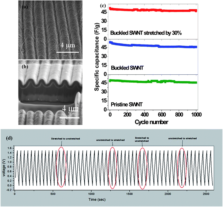 | ||
| Fig. 5 (a and b) SEM images of buckled SWNT macro-films. (c) The comparison of specific capacitance for the supercapacitors based on buckled SWNT macro-films under 30% strain, buckled SWNT macro-films without pre-strain and pristine SWNT macro-films. | ||
The electrochemical properties of the supercapacitors with and without 30% uniaxial tensile strain remain unchanged as shown in Fig. 5c and d. The specific capacitance maintains at 50 Fg−1 and presents a high stability up to 1000 cycles at the high constant current density of 1 Ag−1. The electrical resistance is also remained while being stretched because the buckled SWNT macro-films are able to accommodate the applied tensile strains by self-adjusting the wavy pattern's parameters (increasing the wavelength and decreasing the amplitude). It demonstrates the feasibility of the buckled SWNT macro-films with attractive features in stretchable supercapacitors for the first time.72
Afterwards, a variety of stretchable supercapacitors have been developed. L. Hu et al.73 reported that the supercapacitors with SWNT-soaked conductive fibrous textile electrodes and stretchable fabric as separator have an areal capacitance up to 0.48 F cm−2, the highest result comparable to the commercial values for SWNT. The specific capacitance retains at 62 Fg−1 with and without the strain up to 120% for 100 times, showing a good cycling stability up to 8000 cycles with the retention of capacitance as high as 94% at the constant current density of 1 mA cm−2. Additionally, stretchable graphene,74 SWNT/conductive polymer composites,75 and other innovative wearable supercapacitors with high stretchability (>100% strain) came into the scope of people. However, few of them involves in situ monitoring and investigating the electrochemical behavior of supercapacitors under dynamic cycling stretch, but the ex situ electrochemical measurement under a static strain (SS) state. Following the pioneer work on the buckled SWNT macrofilm-based supercapacitors,69 a fully stretchable supercapacitor constructed with the same components as the previous work except the elastomeric polyurethane (PU) instead of the non-elastomeric filter paper as stretchable separator has been successfully developed.76 The in situ electrochemical performance under dynamic stretching/releasing (DSR) cycles with different stretching strain rates has been examined and evaluated.
It has revealed that the specific capacitances calculated by the CV method at scanning rates from 50 mV s−1 to 2 V s−1 for both the DSR mode and the SS mode are higher when at the maximum strain (31.5%) than at 0% strain. The CV curves (Fig. 6a) at the DSR mode shift between that at 0% SS mode and at 31.5% SS mode. The trend of the shift frequency increase is consistent as the dynamic strain is raised. Under the GCD test (Fig. 6b) at 10 Ag−1, the supercapacitor at the DSR mode also exhibits a higher areal capacitance of 3.47 mF cm−2 at 31.5% strain than 2.64 mF cm−2 when 0% strain is applied. The improved capacitance when stretched is attributed to the increased area of the electrolyte/electrode interface and the facilitated ion diffusion kinetics induced by the applied strain. This is reflected on the results of the electrochemical impedance spectroscopy (EIS) measurement shown in Fig. 6c, where both the charge transfer resistance and Warburg diffusion resistance (WoR) are observed to be significantly decreased.
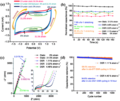 | ||
| Fig. 6 (a) The CV curves for the fully stretchable supercapacitors in three modes: static 31.5% strain; DSR; and static 0% strain at a scan rate of 100 mV s−1. (b) Comparison of the normalized capacitance (normalized by the initial capacitance under static 31.5% strain) with different strain rates. (c) Nyquist plots of the supercapacitors under different strain rates. (d) Capacitance retention at DSR 1.11% and 4.46% rates after long cycling. Reproduced with permission from ref. 73 ©2012, American Chemical Society. | ||
The capacitive behavior is highly reversible and stable within only 2% fluctuation at the DSR mode and the different stretching/releasing rates (1.11%, 2.22% and 4.46% strain per s) could result in slight deviation of electrochemical performance. It is noted that the average normalized specific capacitance of the supercapacitor at 1.11% strain per s is slightly lower (∼1%) than that at 2.22 strain per s and 4.46% strain per s. It is found that increasing the dynamic strain rate would lead to the decreasing of WoR from EIS analysis. This is in agreement with the self-discharge process which becomes slower as the strain rate is lowered. The cyclic stability has also been evaluated by studying the capacitance retention for 1000 cycles at 10 Ag−1 following a long-time of DSR cycles at different dynamic strain rates in advance. It shows both the high capacitance retention of 98.5% after DSR cycling at 1.11% strain per s and of 94.6% after deep DSR cycling at 4.46% in Fig. 6d. The microscale schematic illustrated in Fig. 7 explains how the ion diffusion process varies dynamically at the electrode/electrolyte interface when a strain is applied. Under the DSR mode, the moving of electrolyte inside the cell during stretching/releasing will favor the increase of diffusion ions. It is believed that such in situ electrochemical measurements under the DSR mode are more realistic and practical to evaluate and reveal the true performance of not only the stretchable supercapacitors but also all the stretchable devices.
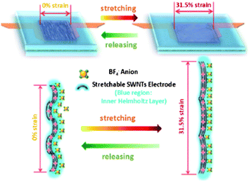 | ||
| Fig. 7 The microscale schematics of the electrode/electrolyte interface in the fully stretchable supercapacitor without and with strains. Reproduced with permission from ref. 73 ©2012, American Chemical Society. | ||
In summary, it has been demonstrated success in assembling and operating the reversibly stretchable supercapacitors using the buckled SWNT macro-films as electrodes, which have controllable wavy geometries and extremely high mechanical stretchability with the utility of PDMS as elastomeric substrates. The stretchable supercapacitors exhibit an excellent electrochemical performance and high cycling stability under both in situ dynamic and ex situ static stretching.
3.2. Electrochemical behavior of SWNT macrofilm-based supercapacitors under compression
The flexible supercapacitors in thin geometrical forms (e.g. thin film) are rapidly developed and embedded in the emerging flexible electronic products in the market, such as the OLED panel display, electronic paper/books, etc. to provide power. In all cases, products with the key characteristic of deformability have to accommodate the deformation in terms of various types of mechanics including compression, bending, and stretching in operation. As the most common force, when a pressure is applied to the flexible devices, the embedded supercapacitor will also experience a significant compressive stress/strain. It is necessary to understand the fundamental characteristics of pressure effects on the supercapacitors to ensure their safety and reliable functionality. Hence, the effect of compression on the electrochemical performance of flexible supercapacitors consisting of SWNT macro-film electrodes and 1 M aqueous electrolytes with different anions and cations were thoroughly investigated. The dependence of pressure on the ion size and the interfacial wettability of different electrolytes with the SWNT macro-film electrode are preliminarily discussed.77 The supercapacitor is assembled in a pouch cell (Fig. 8a) on which the initial pressure is considered as zero. The uniaxial stress is applied vertical to the surface of the SWNT macro-film electrodes by a hydraulic press. As manifested in the SEM image in Fig. 8b, the SWNT film presents a combination of mesoporous and macroporous structure, which allows ions in electrolyte to fully access almost the whole effective surface area of the film to establish the double layer capacitance as schematically illustrated in Fig. 8c. As a result, the counterions are expected to quickly reside at the electrolyte/electrode interfaces and accumulate in the double layer by electrostatic force at the distance of the outer Helmholtz plane. Such a supercapacitor is considered to be an exohedral supercapacitor with a higher power density. Meanwhile, complete ionization to generate free-moving ions in the aqueous electrolyte is another prerequisite condition that is crucial for the following pressure experiments and analysis.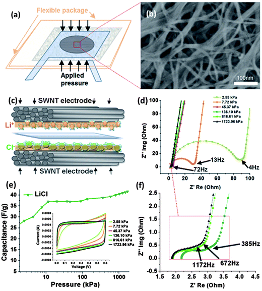 | ||
| Fig. 8 (a) Schematic of supercapacitor assembly with SWNT electrodes. (b) SEM image of the SWNT film electrode (c) Schematic representation of the cations/anions (Li+/Cl−) in aqueous electrolyte/SWNT electrode interface under pressure (d) EIS results with “knee” frequency of the SWNT supercapacitors under increasingly applied pressures. (e) Specific capacitance increase trend under pressure for LiCl electrolytes. (Inset: CV curves with increasing pressure level at 50 mV s−1 scan rate.) (f) EIS results under large pressure applied, where the pressure effect reaches relatively stable phase, in terms of charge transfer resistance. The knee frequency reaches 1172 Hz at 1723.96 kPa. Reproduced with permission from ref. 74 ©2010, American Chemical Society. | ||
Two groups of aqueous electrolytes have been employed: one group is alkaline solutions containing LiOH, NaOH, and KOH, denoted as group A; the other is solutions of neutral salts including LiCl, NaCl, KCl, and KNO3 as group B. The specific capacitances of the electrolytes in group A exhibit an increasing trend before reaching a stable saturated stage as the pressure rises over 70 kPa up to a maximum value of 1724 kPa, while for group B the capacitances of the electrolytes basically stay stable with increasing pressure. It is also noted that with the same cation (K+), the capacitance sequence NO3− > Cl− > OH− in terms of different anions has a positive correlation with the wettability sequence of corresponding anions NO3− > Cl− > OH− under the same pressure. The trend of the capacitance for group A is attributed to the increasing surface wettability induced by the increasing applied pressure until reaching an utmost state. This is also reflected on the trend of CV curves in that the shape becomes more rectangular under the pressure over 70 kPa as shown in Fig. 8e, indicating an ideal capacitive behavior. At the maximum pressure, the specific capacitances for both groups A and B containing different cations show Li+ > Na+ > K+ because the capacitive behavior of the exohedral supercapacitor is still dependent on the hydrated cation sizes. The capacitance increases with the decrease of the ion size (K+ > Na+ > Li+) since smaller cations can access more electrode/electrolyte interfaces and contribute to more charge storage.
The under-pressed resistive features of the supercapacitors were also studied by means of EIS. It is found that the series resistance, the charge transfer resistance, and the Warburg diffusion resistance decrease under an increased pressure from 0 to 1724 kPa. Typically, the Nyquist plot of EIS is divided into two regions by the “knee” frequency, where the high frequency semi-circle is attributed to the charge transfer process occurring at the electrode/electrolyte interface while the low-frequency tails represent the Warburg finite-length diffusion stage.36 The increasing “knee” frequency induced by the applied pressure presents a highest frequency of 1172 Hz for all electrolytes under the maximum pressure of 1724 kPa. It suggests that the “threshold” frequency for charging the supercapacitor is improved up to 1172 Hz, significantly higher than reported values (a few Hz to 300 Hz),13,78,79 indicating an excellent high-power capability.
This work not only provides fundamental insight of pressure effects on the electrochemical behavior of supercapacitors, but also gives an important guideline for the packaging process and predicting the durability of flexible supercapacitors.
3.3. Pseudocapacitors based on SWNT/MnO2 hybrid macro-films
Pseudocapacitors can deliver a capacitance 10–100 times that of EDLCs because they not only store charges in the double layer but also take advantage of the charge transfer through the fast and reversible Faradaic reactions.80 It requires that electrode materials have electrochemically redox activity with the electrolytes. In general, conductive polymers and the electroactive metal oxides constitute this type of supercapacitors. Despite the high conductivity and highly reversible storage capacity the conductive polymers possess, it would unfortunately suffer swelling and shrinking during the redox process (ionic intercalation/deintercalation), resulting in the mechanical degradation of the polymer electrode and fading of electrochemical performance during cycling of less than 1000 cycles.81,82 In contrast, metal oxides have a better stability while undergoing more than 10![[thin space (1/6-em)]](https://www.rsc.org/images/entities/char_2009.gif) 000 cycles but worse conductivity, which compromises the fast electrochemical Faradaic reactions.83 RuO2,84–87 MnO2,88–90 Co3O4,91 NiO,92 and V2O5,93 which have redox couples of transition metal ions and allow the facile ion interconversion of O2− + R+ ↔ OR−, have been extensively investigated. To overcome the drawbacks of low conductivity and low power density, the concept of nanocomposite combining metal oxides with carbon nanomaterials, in particular CNTs, has been proposed and intensively studied. The CNTs have many significant effects in nanocomposites as follows:52
000 cycles but worse conductivity, which compromises the fast electrochemical Faradaic reactions.83 RuO2,84–87 MnO2,88–90 Co3O4,91 NiO,92 and V2O5,93 which have redox couples of transition metal ions and allow the facile ion interconversion of O2− + R+ ↔ OR−, have been extensively investigated. To overcome the drawbacks of low conductivity and low power density, the concept of nanocomposite combining metal oxides with carbon nanomaterials, in particular CNTs, has been proposed and intensively studied. The CNTs have many significant effects in nanocomposites as follows:52
• The inherent superior conductivity of CNTs could improve the electrical conductivity of nanocomposites greatly.
• The large specific surface area of CNTs could favor the dispersion of metal oxide nanoparticles.
• That CNTs induce more porosity to the nanocomposite electrode facilitates the charge transfer by providing more channels for electrolyte access and reducing the ion diffusion distance.
• The functional groups on the surface of CNTs could enable the transport of solvated ions to the electrolyte/electrode interfaces and increase the Faradaic reaction sites of metal oxides.
The electrochemical performance of various carbon–metal oxide nanocomposites reported in the literature is summarized in Table 1 as follows:
| Metal oxides–carbon nanocomposites | Amount of metal oxides loading (%) | Specific capacitance based on composite electrodes (F g−1) | Specific capacitance based on metal oxides alone (F g−1) | Electrolyte | References |
|---|---|---|---|---|---|
| RuO2/carbon black | 27 | 221 | 854 | 1 M H2SO4 | 85 |
| RuO2/carbon black | 40 | 407 | 863 | 1 M H2SO4 | 85 |
| RuO2/CNT | 17 | — | 1192 | 0.5 M H2SO4 | 86 |
| RuO2/graphene | 38.3 | — | 570 | 1 M H2SO4 | 87 |
| MnO2/CNT/PEDOT-PSS | 60 | — | 129 | 1 M Na2SO4 | 88 |
| MnO2/carbon | 70 | 218 | — | 1 M Na2SO4 | 89 |
| MnO2/carbon | 83 | 166 | — | 1 M Na2SO4 | 89 |
| MnO2/graphene oxide | 90.7 | 197.2 | 211.2 | 1 M Na2SO4 | 90 |
| Co3O4/graphene | 24.4 | — | 243.2 | 6 M KOH | 91 |
| NiO/CNT | 50 | 523.37 | 1037.74 | 6 M KOH | 92 |
| NiO/CNT | 80 | 326.2 | 405.5 | 6 M KOH | 92 |
| V2O5/CNT | 80 | 288 | — | 1 M LiClO4 | 93 |
Although RuO2 has an ultrahigh specific capacitance over 1300 Fg−1 when reduced to nanoscale in various structures to increase the surface area and paths of diffusion,81 MnO2 with similar high theoretical capacities over 1100 Fg−1, in addition to low cost, eco-friendliness, and natural abundance attracts more attention and research efforts to reduce the use of or replace precious metal eventually.82 Compared with a diversity of other strategic routes to fabricate the MnO2/CNT nanocomposite such as electrodeposition,94 hydrothermal method,95 mechanical mixing,96etc., in situ deposition of MnO2 nanoparticles on SWNT macro-films at room temperature (RM) to form SWNT/MnO2 hybrid film is more facile and effective. A modified method is developed based on the simple precipitation to synthesize the nanostructured MnO2 through direct reduction of KMnO4 by ethanol.97 The electrode with the purified SWNT macro-film is simply immersed in ethanol and in situ deposition occurs between the absorbed ethanol molecules on the surface of SWNT macro-films and the dropwise added KMnO4, as illustrated in Fig. 9. Within 0–30 min of reaction, the SWNT bundles are deposited by a layer of MnO2 nanoparticles with controllable mass as shown in the SEM images (Fig. 9b and c). The resulting SWNT/MnO2 electrodes after being rinsed in deionized water and dried naturally at RM without any other post-treatment are then assembled into a symmetric two-electrode cell in 1 M TEABF4/PC electrolyte. The SWNT/MnO2 hybrid macro-films have a maximum capacitance of 151 Fg−1 based on the total mass of the SWNT/MnO2 hybrid macro-film and 595 Fg−1 based on the mass of MnO2 only at 2 mV s−1 in the CV measurements. The CV curves at an extremely high scan rate of 2 V s−1 also present a typical rectangular shape, analogous to non-faradaic processes such as EDLCs. This indicates a highly reversible Faradaic reaction of MnO2 due to the improved conductivity by SWNT. For the GCD test at a small current density of 0.1 Ag−1, the energy density could reach 70 W h kg−1 while keeping a high power density of 79 kW kg−1. At 2 Ag−1, the specific capacitance remains stable for 1000 cycles in the range from 118 Fg−1 to 121 Fg−1, which is three times that for the pristine SWNT macro-film electrodes (∼40 Fg−1). The hybrid macro-films also exhibit an excellent cycling stability up to 15![[thin space (1/6-em)]](https://www.rsc.org/images/entities/char_2009.gif) 000 cycles with a high capacitance retention of 98.5% at a current density as high as 50 Ag−1. Four major advantages of the SWNT/MnO2 hybrid macro-films are inherited from the SWNT films: binder free, robustness, high conductivity, and excellent ion paths owing to the porous structure of the SWNT macro-films. This facile synthesis demonstrates a cost-efficient and large-scale production of psedocapacitors in industry.
000 cycles with a high capacitance retention of 98.5% at a current density as high as 50 Ag−1. Four major advantages of the SWNT/MnO2 hybrid macro-films are inherited from the SWNT films: binder free, robustness, high conductivity, and excellent ion paths owing to the porous structure of the SWNT macro-films. This facile synthesis demonstrates a cost-efficient and large-scale production of psedocapacitors in industry.
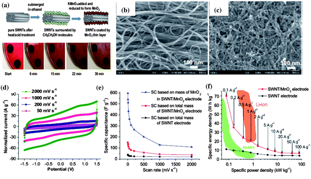 | ||
| Fig. 9 (a) Schematic illustration of the synthesis of MnO2/SWNT hybrid macro-films and the corresponding snapshots of the reaction process. (b) SEM image of pure SWNT macro-films. (c) SEM image of MnO2/SWNT hybrid macro-films after MnO2 deposition. (d) CV curves of MnO2/SWNT electrodes measured at different scan rates. (e) Comparison of specific capacitances between MnO2/SWNT electrodes based on total mass of hybrid macro-films and mass of MnO2 and pure SWNT electrodes at different scan rates. (f) Ragone plots of MnO2/SWNT electrodes and SWNT electrodes compared with Ni–MH and Li–ion batteries. Reproduced with permission ©2012, Elsevier Ltd. | ||
3.4. Effect of temperature on the capacitance of SWNT macrofilm-based supercapacitors
Supercapacitors that could offer high energy and power densities and at the same time withstand a variety of rigorous temperature conditions such as repeated heating and cooling, continuous heating, etc. have become extremely desirable for military and space applications. Particularly in hybrid electric vehicles, supercapacitors can be coupled with fuel cells or batteries to deliver the high power and withstand the long heating–cooling cycles during vehicle start-up/acceleration and braking to recover the energy. Based on the free-standing SWNT macro-films and 1 M TEABF4 in PC with a higher decomposition temperature than aqueous electrolytes, we have successfully developed an organic supercapacitor that can be operated stably in a wide temperature range from 25 to 100 °C within a large voltage window (−1.5 V to 1.5 V).98 The electrochemical performance of supercapacitors as a function of temperature at 25, 50, 75 and 100 °C was studied. Within such a wide temperature window of 25–100 °C, the supercapacitors behave as ideal rectangular shapes in CV curves with a specific capacitance range between 30 and 40 Fg−1 (at 50 mV s−1). The pseudocapacitive peaks in CV became increasingly distinct with the temperature increases, corresponding to the occurrence of the reversible Faradaic reactions which resulted from the physisorbtion of electrolyte ions on the modified surface of SWNTs by electrolyte vapor evaporated at a high temperature.99,100 EIS analysis by fitting the Nyquist results using a modified Randles equivalent circuit indicates that higher temperature operation could improve the diffusivity of ionic charges and hence the electrochemical performance of the supercapacitors. The long cycle GCD measurements also confirm the enhancement of the supercapacitor performance when returning to room temperature after repeated heating and cooling cycles and the stability under such rigorous condition. The supercapacitor is capable of withstanding high current densities at 20, 50 and 100 Ag−1, yielding a specific power density value of 55 kW kg−1. An ultra-long GCD cycling over 200![[thin space (1/6-em)]](https://www.rsc.org/images/entities/char_2009.gif) 000 cycles at 25 °C and 100 °C under the constant current density of 20 Ag−1 reveals the excellent stability with high capacitance retention of 82% and 84%, respectively (Fig. 10). The thorough evaluation of the temperature effect on electrochemical behavior as well as the kinetics and the diffusion mechanism in the SWNT macrofilm-based supercapacitors in 1 M organic electrolyte prove their potential usage as power sources that can operate at high temperatures.
000 cycles at 25 °C and 100 °C under the constant current density of 20 Ag−1 reveals the excellent stability with high capacitance retention of 82% and 84%, respectively (Fig. 10). The thorough evaluation of the temperature effect on electrochemical behavior as well as the kinetics and the diffusion mechanism in the SWNT macrofilm-based supercapacitors in 1 M organic electrolyte prove their potential usage as power sources that can operate at high temperatures.
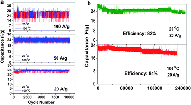 | ||
| Fig. 10 (a) The capacitance of SWNT macro-film supercapacitors under 25 and 100 °C at different current densities of 20 Ag−1, 50 Ag−1 and 100 Ag−1 with cycles. (b) Capacitance retention under 25 and 100 °C at the current density of 20 Ag−1. Reproduced with permission from ref. 98 ©2009, American Chemical Society. | ||
3.5. Self-discharge process of SWNT macrofilm-based supercapacitors
The self-discharge (SDC) is an intrinsic and undesirable phenomenon to all the electrochemical energy storage devices, which leads to fast fading of capacity stability and is detrimental to the long life usage of the power sources. However, SDC, generally thermodynamically driven by the higher state of potential energy, for a supercapacitor is substantially higher than those for LIBs.8 Thus, understanding the SDC mechanisms of supercapacitors and associated dominant factors is crucial to obtaining the supercapacitors with tunable energy retention. In our previous work on the SDC of EDLCs in the assembly of active carbon fibers (ACF) in organic electrolytes,101 the corresponding SDC processes were proposed under three major conditions of different driving forces: potential field V, ion concentration gradient ∇c, and their synergetic effect, assuming no chemical reaction occurs during the charge and discharge. The variation of the SDC processes is a result of the competition between the strength of driving forces. We have systematically examined the SDC processes of the supercapacitors with the free-standing SWNT macro-films as electrodes and 1 M TEABF4 in PC as electrolyte102 under different temperatures from the charged state. Compared with the ACF–TEABF4 system, the SDC curves after charging with different current densities Ic from 10 mA g−1 to 1 Ag−1 at 25 °C exhibit a much higher discharging rate and a smaller initial voltage drop as Ic increases, indicating both the excellent electrical and ionic conductivity of the SWNT macro-film electrodes. As the ACF–TEABF4 case implied, the potential field V would take control of the SDC for a supercapacitor with a high initial voltage and a low specific capacitance.Nevertheless, it is unusual that for the SWNT–TEABF4 supercapacitors, the SDC behavior could neither be explained by the single potential driving (SPD) model
| V = V1e−t/τ1 + V2e−t/τ2 + V0, τ1 > τ2 | (7) |
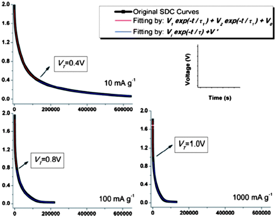 | ||
| Fig. 11 Experimental SDC curves (black) and the fitting curves in DPD model (red) and SPD model (blue) marked with transition voltage VT. Reproduced with permission from ref. 90 ©2011, The Royal Society of Chemistry. | ||
The ratio V2/V1 represents the relative amounts of ions that contribute to the faster (smaller τ) and slower (larger τ) SDC processes corresponding to the two SPD components. In further analysis, the division of V1e−t/τ1 and V2e−t/τ2 corresponds to the co-existed strong bonding and weak bonding between electrolyte ions and electrodes respectively, which acts as the barrier impeding charges that are self-discharged out of the Helmholtz double layer. The V2e−t/τ2 part of the equation vanishes quickly as the faster SDC process is finished at the VT since where the DPD model merges to become a SPD model. The variation of the strong bonding and weak bonding derives from interference of the functional groups on the surface of SWNTs: the small amounts of functional groups may weaken the initial strong bonding between SWNT and ions by electrostatic interaction. This new “DPD → SPD” SDC model is verified by expanding to a large temperature range (−25 °C to 75 °C). Overall, the proposed “DPD → SPD” SDC model will shed light on selecting an optimum condition combination (e.g. charge current density and SDC temperature) to tune the supercapacitors' energy retention.
4. SWNT macro-film-based electrodes for LIBs
Compared with supercapacitor, lithium–ion battery with a high voltage window beyond 3 V and much higher energy density ranging from 100 W h kg−1 to 150 W h kg−1 is already widely used in portable electronics (e.g. laptops and cell phones), especially with the popularization of the smart phones.103 A typical structure of a commercial LIB consists of a graphite anode, a cathode formed by lithium metal oxide such as LiCoO2, and a separator embedded in an organic electrolyte containing a lithium salt (e.g. 1 M LiPF6 in 1![[thin space (1/6-em)]](https://www.rsc.org/images/entities/char_2009.gif) :
:![[thin space (1/6-em)]](https://www.rsc.org/images/entities/char_2009.gif) 1 of diethyl carbonate (DEC) and ethylene carbonate (EC) by volume). The schematic in Fig. 12 illustrates the working principle of LIBs involving the electrochemical reactions at both electrodes in eqn (8) and (9):
1 of diethyl carbonate (DEC) and ethylene carbonate (EC) by volume). The schematic in Fig. 12 illustrates the working principle of LIBs involving the electrochemical reactions at both electrodes in eqn (8) and (9): | (8) |
 | (9) |
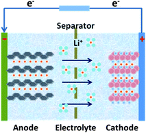 | ||
| Fig. 12 The schematic illustration of the working principle of Li–ion batteries. | ||
The anode is the source of lithium ions and the cathode serves as the sink for the lithium ions. The electrolyte promotes the ionic transport which is separated from the electronic transport that happens in the external circuit via electron flow to supply power. Throughout the charging process, lithium migrates from the cathode (LiCoO2 in this case) through the electrolyte and is intercalated into the graphite anode (LixC6). During discharge, the movement of lithium is in a reverse process: Li ions are extracted from the anode and intercalated into the cathode.
The reversible capacity of LIBs during charge and discharge is determined by the reversible Li+ transport between electrolyte and electrode. The theoretical specific capacity of the active electrode materials is the maximum Li+ which can be stored in the matrix of the materials per unit mass calculated by the maximum stoichiometry of the reversibly-lithiated products (e.g. the LixC6, x ≤ 1). GCD is the most common method to evaluate the specific capacity, high-rate capability, and cyclic stability of LIBs at various constant current densities. However, there is a tremendous amount of electrode materials with a considerable difference in theoretical specific capacity. Thus, in order to better implement the measurements, it is convenient to define the current density applied to an arbitrary material with the theoretical specific capacity to make it finish a one-time charge or discharge within 1 h to be 1 C. For example, the theoretical specific capacity for SnO2 is 781 mA h g−1,104 so 1 C for the GCD test is 781 mA g−1. This method is widely adopted for both academic and industrial use. In addition, CV and EIS are also relied on to evaluate the electrochemical performance.
Currently, the electrochemical performance of LIBs is mainly limited by the deterioration in the poor conductivity (partly due to the deposition of insulating products), morphology and microstructure change, volumetric expansion and contraction, as well as the irreversible phase transformation associated with the active electrode materials during the cycling of lithium ion insertion and extraction.105 In order to ameliorate the challenge to develop next-generation LIBs with a high power density and long lifetime, nanomaterials with a diversity of structures or architectures are intensively explored due to the unique advantages as follows:105
• Large surface area increases the contact area between electrolyte and electrode and the number of active sites for electrode reactions.
• Shortened diffusion length for Li ions and electrons transport into the solid state electrode materials with nano-sized dimensions and meso- or macro-porous structure.
• Enhanced ionic and electronic conductivity by introducing conductive additives or assembly of nanocomposite.
• Improved mechanical strength and structural integrity which undergo long-term cycling.
The SWNT macro-films perfectly possess all the four characteristics above and hence hold the promise to combine with other active materials to form novel nanostructured composites as binder-free electrodes for high performance LIBs. The followings are just two examples to illustrate different functionality of the SWNT macro-films for LIB anodes.
4.1. In situ formation of sandwiched structures of SWNT macro-film/CuxOy nanocomposites
The unique property of the SWNT macro-films, that they can be deposited on flexible substrates, should be reiterated for the LIB applications because it extremely simplifies the processing of electrode preparation by shortcutting the material-to-electrode steps in production. The electrodes can be fabricated by direct deposition of the SWNT macro-films on current collectors (for instance, copper foils as anodes) for LIBs. Both the structure and the electrochemical property of the anodes assembled in two-electrode test cells with Li metal as a reference and counter electrode in a electrolyte of 1 M LiPF6 in EC:DEC have been investigated.As discussed in previous sections, the SWNT macro-films are composed of entangled SWNT bundles in perfect structural uniformity, which has formed good adhesion with the Cu-foil substrate.106 It is worthy to note that a thin layer of copper oxide, which has been confirmed by XPS measurements, was formed at the interface between the SWNT macro-film on the top and the Cu substrate at the bottom during the direct deposition process. A typical schematic of such a sandwiched structure with SWNT macro-film/CuxOy/Cu in a half cell configuration is shown as the inset of Fig. 13a. The differential capacity plot and cyclic voltammetry show the reversible peaks at around 1.8 V corresponding to CuxOy, confirming the formation of the copper oxide layer. The sandwiched system exhibits an excellent capacity of 220 mA h g−1, even at an ultrahigh current density of 50 C. The high rate capability of the SWNT/CuxOy/Cu sandwiched system is attributed to the following reasons:
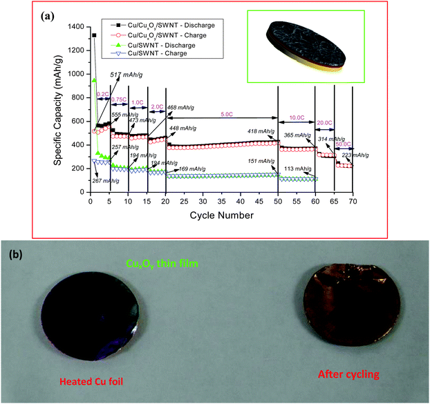 | ||
| Fig. 13 (a) Comparison of the charge–discharge performance of the batteries with the Cu/CuxOy/SWNT sandwiched structure as electrode and the Cu/SWNT film electrode. Inset: schematic illustration of the sandwiched structured SWNT/CuxOy/Cu anode. (b) Photographs of heated Cu foil and the copper foil after the first discharge cycle. From the color on the surface of the coils, it is clear that the copper oxide is converting into copper during the Li insertion (discharge) process. Reproduced with permission from ref. 95 ©2009, American Chemical Society. | ||
(1) Li insertion reaction into the copper oxide would lead to the formation of Cu nanoparticles (CuO + 2Li+ + 2e− → Li2O + Cu), as shown in Fig. 13b. The presence of the resulting Cu nanoparticles at the electrolyte/electrode interface from migrating into the SWNT bundles with the flooding of electrolyte could improve the electronic conductivity remarkably and play a catalytic role in facilitating the Li ion transfer rate across the interface. The decrease in the resistivity and the activation energy favors the Li ion diffusion even at a high charge–discharge rate. Also, the highly conductive SWNT macro-film over the copper oxide layer will further enhance the electron exchange reactions.
(2) In the reverse reactions by removal of Li ions, there is a formation of Cu2O nanoparticles by the decomposition of Li2O.107 During this disproportion reaction, there is always an oxygen evolution reaction and the evolved oxygen is expected to be physiadsorbed by the SWNT macro-film. The adsorption of oxygen by SWNT would increase the electrical conductivity by at least two orders of magnitude.108 The improved electronic properties during the electrochemical insertion of Li ions contributed to the high rate performance (50 C) of the sandwiched composite electrodes.
The above mentioned inferences and analysis have been further confirmed by EIS measurements. It is found that electrical impedance of the cell with the sandwiched structure (SWNT/CuxOy/Cu) is much lower than that of the cell without the intermediate copper oxide layer (SWNT/Cu). Therefore, the improvement in electrochemical performance involving a sandwiched composite architecture could be extended to provide guidance to SWNT macro-film/other metal oxides systems for LIB electrodes.
4.2. Tandem structures of porous silicon/SWNT macro-film
Silicon (Si) is one of the attractive anode materials for LIBs because of a low discharge potential (∼0.3 V versus Li+/Li) and the highest known theoretical charge capacity of 4200 mA h g−1 (one mole of Si is able to accommodate 4.4 moles of Li leading to formation of an Li22Si5 alloy).109 However, the severe drawbacks of pulverization and early capacity fading due to the large volumetric change (400%) upon insertion and extraction of lithium limit the development of an Si-anode.110 One common strategy is to explore the Si in nano-sized structures to improve the electrochemical properties. Among various successfully-synthesized Si nanostructures such as nanoparticles,111 nanowires,112 and nanotubes,113 Si film in nano-dimension is preferred in compatibility with semiconductor techniques for scale-up production without any binder; however, the good adherence and contact between the Si film and a current collector with modified surfaces by complicated chemical etching, electroplating, and other treatments is hard to maintain during cycling, which is detrimental to the cyclic stability and lifetime for LIBs.114,115The SWNT macro-films are intrinsically flexible and can be deformed when a load applies. It is expected that they can act as a buffer layer between the Si films and the current collectors to better accommodate stress induced by Li ion insertion. Thus, we have successfully demonstrated a tandem structure formation of a thin porous Si film (∼300 nm) on a SWNT macro-film via physical deposition as anodes for LIBs.116 The reversible specific capacity of the Si–SWNT composite retains 2221 mA h g−1 with 82% retention after 40 cycles of charge and discharge at 0.1 C, compared with a faster degradation of capacity and poor retention (42%) for the Si–Cu control sample without the SWNT layer, indicating that the tandem structure has a better stability than that of the pure Si film (Fig. 14 bottom). Structural evolution of such a tandem structure during cycling have shown (Fig. 14 top-right) that the initial convex morphology with caps of cone-shape “lattices” of the Si film is evolved to be a porous structure after releasing the internal stress by removing some small pieces of Si cones, as illustrated in the schematic (Fig. 14 top-left). However, the Si film after cycling still holds tightly onto the SWNT macro-film, exhibiting an excellent robustness towards volumetric expansion due to Li-insertion and also the good adhesion of the SWNT film between Si and the copper substrate. EIS measurements show that the charge transfer resistance of the pure Si films increases significantly during cycling in comparison with that of the tandem Si–SWNT samples. The larger electrochemical reaction resistance for the pure Si sample is caused by the electronic contact loss during the lithiation/delithiation process. These results are in agreement with SEM observations and cyclic performance.
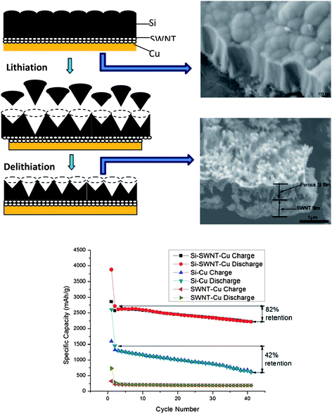 | ||
| Fig. 14 Up-left: schematic representative (cross-section view) of structural evolution of silicon film upon charge–discharge cycling with the SWNT macrofilm as a buffer layer between the deposited Si film and the copper current collector. Up-right: SEM images of as-prepared Si–SWNT–Cu sample with columnar grain feature and the porous structure after 40 cycles as an electrode. Bottom: comparison of cycling performance of the batteries with Si–Cu, Si–SWNT–Cu and SWNT–Cu samples as electrodes at constant current 0.02 C in the first cycle, and 0.1 C in the remaining 40 cycles. Reproduced with permission from ref. 105 ©2010, American Chemical Society. | ||
In summary, the deformable SWNT macro-films with a large specific surface show success as a buffer layer to mitigate the volumetric expansion and shrinkage of Si films for LIBs. The tandem structure offers an effective solution for a high-performance LIB based on the Si thin film as an anode.
5. Future directions for Li–S and Li–air batteries based on SWNT macro-films
The rapid progress of electric vehicle technologies demands innovation of new battery chemistry beyond Li–ion systems and this significant step change in energy storage is migrating to Li–S and Li–air batteries with capacity over at least a factor of 5-fold higher than that of LIBs.Li–S battery
The battery configuration of Li–S is different from that of conventional LIBs, so therefore is the working principle as illustrated in Fig. 15. A typical Li–S battery is similar to the half cell assembly for electrochemical characterization. It is composed of lithium metal as anode, and sulfur, which is usually embedded in the conductive supporting materials (e.g. conductive polymer117 and carbon118) instead of the lithium transition–metal oxide or phosphate in the LIBs, as cathode. The rechargeability of Li–S is mainly relying on the redox reactions: | (10) |
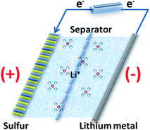 | ||
| Fig. 15 The scheme of the working mechanism of Li–S batteries. | ||
Sulfur is reduced by lithium to a series of intermediate polysulfides Li2Sn (1 < n < 8). Although it has only 2/3 of the potential of that for cathodes in LIBs such as LiCoO2, this is offset by the super high theoretical capacity of 1675 mA h g−1 due to the light weight of sulfur and the large amounts of Li ion transfer (up to 8 moles of Li ions for 1 mole of sulfur).119 However, sulfur is a highly electrically and ionically insulating material and as a cathode it would suffer from active mass loss, low Coulombic efficiency, and rapid capacity fading caused by the “shuttle effect” that the soluble polysulfides Li2Sn (3 < n < 8) transport between cathode and anode cyclically.120 During cycling, the soluble polysulfides would react with lithium anode directly to precipitate the insulating Li2S2 and Li2S on the anode, decreasing the conductivity of lithium while the Li2S2 and Li2S can reduce the Li2Sn (n = 8–10) to Li2Sn (3 < n < 8), which will diffuse back to the cathode to be re-oxidized.120
To improve the electrochemical activity and cyclic stability of Li–S batteries, the most common strategy is to incorporate sulfur into a host matrix with mesoporous structures to hinder the “shuttle effect”. Carbon nanomaterials with a high pore volume show the promise to be employed as the host to form carbon/sulfur composites as illustrated in Fig. 16. L. F. Nazar et al.119 have reported that sulfur can be confined in the interconnected channels of the mesoporous carbon CMK-3, exhibiting a high reversible capacity up to 1320 mA hg−1 with an improved cyclic stability. CNTs with the unique hollow tube structures are also considered as an ideal framework to design new architectures such as a homogenous highly-dispersed sulfur/CNT nanocomposite121 and CNT–S in a core–shell structure122 to immobilize the sulfur molecules from dissolving into electrolytes.
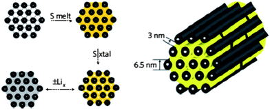 | ||
| Fig. 16 Carbon nanomaterials with high pore volume as the host to form carbon/sulfur composite to immobilize sulfur. Reproduced with permission from ref. 108 ©2009, Macmillan Publishers Limited. | ||
However, there still exist limitations to extend the life of battery beyond 100 cycles with high a Coulombic efficiency as well as stable capacity retention by using simply physical constraining of sulfur in CNT and other carbon nanomaterials. Therefore, it is expected that a more effective method for further improvement is to create stronger interaction (e.g. chemical bonding) between the sulfur molecules and carbon materials and also to reduce the size of the octatomic S8 molecules to smaller S6 or S2. Following this idea, Chen122et al. reported a hierarchical S/MWNT (multi-walled CNT) architecture that is synthesized by coating sulfur uniformly on the surface of functionalized MWNT. C. Wang et al.123 also demonstrated the improved cycling stability and Coulombic efficiency for the sulfur impregnated in the disordered CNTs by the infusion of smaller sulfur molecules at a high temperature. Recently, K. Amine et al.124 and A. Manthiram et al.125 reported the nanocomposite of sulfur and mesoporous carbon and graphene, respectively, which are formed via hydroxyl groups of carbon nanostructured materials by a one-step deposition reaction.
It is envisioned that SWNT macro-film/S nanocomposite could be developed by the similar one-step deposition of sulfur. The oxygen-containing functional groups of the SWNT macro-films after purification could provide more sites to fasten highly-dispersed sulfur at a higher percentage. The nanocomposite can be used directly as the cathode without binder for Li–S batteries to enhance the electrochemical performance.
Li–air battery
Based on different electrolytes, Li–air batteries could be classified into two groups: aqueous and nonaqueous. The nonaqueous Li–air batteries have became the focus of research due to their most promising quality of rechargeability. The nonaqueous Li–air battery is typically composed of a metallic lithium anode, an electrolyte comprising a lithium salt dissolved in a nonaqueous organic solvent, and a porous O2-breathing cathode. The working mechanism is schematically shown in Fig. 17a. During the discharge of the cell, Li metal offers Li ions by oxidation at the anode: Li → Li+ + e−. The electrons flow through an external circuit to perform work in the load and reduce the oxygen at the cathode with the lithium ions generated from the anode in a reversible route: 2Li+ + O2 + 2e− ↔ Li2O2. The process is reversed upon charging.126 In the nonaqueous Li–air batteries, porous carbon materials with a high conductivity and large surface area (e.g. super P active carbon black) are recognized and often chosen as the ideal architectures for the O2 breathing cathode to facilitate the electrochemical reactions. Pore size is a key parameter to the electrochemical performance of Li–air batteries. The optimum pore size distribution is anticipated to be in the range of 10–200 nm.120 If the pores are too large, the resulting low surface area may compromise rate and rechargeability while if the pores are too small, the solid insulating product Li2O2 may fill in the pores and block the O2 access, slowing the rate as well as decreasing the electrochemical activity of the electrode. It also requires that the cathode has a good wettability with the electrolyte and could prevent H2O and CO2 while only allowing O2 to penetrate.127 Thus, it is expected that the SWNT macro-films with a tunable micro-to-meso-porous structure and hydrophobic surface as shown in Fig. 17b and c hold the potential to be a qualified cathode material.41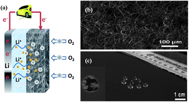 | ||
| Fig. 17 (a) The scheme of Li–O2 batteries. (b) The SEM image showing micro-to-meso-porous structure of SWNT macro-films. (c) The photograph of the hydrophobic surface of the SWNT macro-films. (b) and (c) are reproduced with permission from ref. 37 ©2007, The Royal Society of Chemistry. | ||
The existence of a large overpotential gap between charge and discharge voltages for Li–air batteries results in inefficiency in energy storage. Various catalysts ranging from bifunctional metal such as Pt–Au128 to transition metal oxide such as α-MnO2 (ref. 129) have been incorporated with porous carbon materials in order to reduce the overpotential. In Section 3.2, the SWNT/MnO2 hybrid macro-film that has been demonstrated to possess promising electrochemical properties in pseudocapacitors is likely to be extended to Li–air batteries with good functionality.
6. Summary and perspectives
In this perspective, we have described the fabrication method and unique properties of the SWNT macro-films. We have also investigated the applications of the SWNT macro-films in various energy storage devices. It is well-known that every potential application benefits from a combination of two or more dominant properties of the SWNT macro-films including structures, electronics, electrochemistry, and so on. Thus, instead of evaluating the functionality of the SWNT macro-films encapsulated in discrete devices one by one, it is meaningful to extract the common or related characteristics out of these various energy storage devices based on the SWNT macro-films and to overlook them in a systematical view.Pre-known properties of CNTs
The inherent superior conductivity, large specific surface area, and porous structure will facilitate the charge transfer by providing more channels for electrolyte access and reducing the ion diffusion distance.Stretchability
By buckling SWNT macro-film in a wavy form, the stretchable supercapacitor can be realized to withstand the large strain (>30%) generated from large stretching (≫1%). The assembly of a fully-stretchable supercapacitor with elastomeric separator and the buckled SWNT macro-film is achieved and tested by in situ electrochemical measurements under dynamic stretching/releasing cycles.Thermo- and mechanical-stability
The supercapacitor is capable of working with a good cyclic stability regardless of being under repeated heating and cooling cycles between 25 °C and 100 °C or a high compressive stress up to 1724 kPa.Enhancement of electrochemical performance by external factors applied
Both the static stretching and dynamic stretching/releasing condition will favor the ionic diffusion to enhance the specific capacitance compared with the pristine SWNT macro-films. The increasing surface wettability induced by the increasing applied pressure will contribute to the excellent high-power capability of the SWNT macrofilm-based aqueous supercapacitors. The higher temperature can facilitate the diffusion of ionic charges to improve the capacitance of the supercapacitors. The cyclic stability of the LIB in Si–SWNT tandem-structure is enhanced due to the fact that internal stress of Si films induced by Li ion insertion/extraction is alleviated extensively by the deformable SWNT macro-films with large specific surface as a buffer layer.Significant effects of functional groups
The presence of oxygen-containing functional groups on the surface of the SWNT macro-films after purification can enhance the adhesion of the SWNT films with PDMS elastomer through a strong interfacial bonding (covalent bonds –C–O–Si–) in the stretchable supercapacitors; enable the transport of solvated ions to the electrolyte/electrode interfaces and increase the Faradaic reaction sites of MnO2 nanoparticles in the pseudocapacitor based on the SWNT/MnO2 hybrid macro-films; lead to the variation of the strong bonding and weak bonding by interference of the initially strong electrostatic interaction and is responsible for the “DPD → SPD” SDC model; and enhance the adherence to the current collector (e.g. Cu foil) and Si thin film.Property changes associated with the physisorption of gases
The pseudocapacitive behavior of the supercapacitor based on the SWNT–TEABF4 system is becoming increasingly distinct with the temperature increases because of the physisorption of electrolyte ions on the modified surface of SWNTs by electrolyte vapor evaporated at a high temperature. On charging the LIBs with the sandwich-structured SWNT/CuxOy/Cu anodes, the resistance is decreased owing to the physisorbed oxygen by an oxygen evolution reaction from the disproportion reaction of Li2O on the surface of the SWNT macro-film.In the end, taking the significant effect of functional groups and the common preliminary properties of CNTs into account, we expect that the SWNT macro-films hold the promise in future applications in Li–S and Li–air batteries.
Acknowledgements
The authors thank all co-workers who have performed the experiments cited in this paper: Dr Hanqing Jiang, Dr Hongwei Zhu, Dr Charan Masarapu, Dr V. Subramanian, Mr Jiepeng Rong, Mr Xin Li and Ms. Qing Zhang et al. The authors are grateful for the financial supports from US NSF-0753462, NSF-0926093, NSF-1138182, and NSF-1067960. BQW would also acknowledge the support from the State Key Laboratory of Solidification Processing (NWPU), China (Grant no. 83-TZ-2013).References
- P. Simon and Y. Gogotsi, Nat. Mater., 2008, 7, 845–854 CrossRef CAS PubMed.
- M. Armand and J. M. Tarascon, Nature, 2008, 451, 652–657 CrossRef CAS PubMed.
- J. M. Tarascon and M. Armand, Nature, 2001, 414, 359–367 CrossRef CAS PubMed.
- T. Horiba, T. Maeshima, T. Matsumura, M. Koseki, J. Arai and Y. Muranaka, J. Power Sources, 2005, 146, 107–110 CrossRef CAS PubMed.
- J. R. Miller and P. Simon, Science, 2008, 321, 651–652 CrossRef CAS PubMed.
- K. H. An, W. S. Kim, Y. S. Park, J. M. Moon, D. J. Bae, S. C. Lim, Y. S. Lee and Y. H. Lee, Adv. Funct. Mater., 2001, 11, 387–392 CrossRef CAS.
- B. W. Ricketts and C. Ton-That, J. Power Sources, 2000, 89, 64–69 CrossRef CAS.
- B. Conway, Electrochemical supercapacitors: scientific fundamentals and technological applications (POD), Kluwer Academic/plenum, New York, 1999 Search PubMed.
- P. G. Bruce, S. A. Freunberger, L. J. Hardwick and J.-M. Tarascon, Nat. Mater., 2011, 11, 19–29 CrossRef PubMed.
- C. Xu, B. Xu, Y. Gu, Z. Xiong, J. Sun and G. Zhao, Energy Environ. Sci., 2013, 6, 1388–1414 CAS.
- M. Ue, K. Ida and S. Mori, J. Electrochem. Soc., 1994, 141, 2989–2996 CrossRef CAS PubMed.
- S. Xu, Y. Zhang, J. Cho, J. Lee, X. Huang, L. Jia, J. A. Fan, Y. Su, J. Su and H. Zhang, Nat. Commun., 2013, 4, 1543 CrossRef PubMed.
- E. Frackowiak and F. Beguin, Carbon, 2001, 39, 937–950 CrossRef CAS.
- A. Fuertes, G. Lota, T. Centeno and E. Frackowiak, Electrochim. Acta, 2005, 50, 2799–2805 CrossRef CAS PubMed.
- Y. Gogotsi, A. Nikitin, H. Ye, W. Zhou, J. E. Fischer, B. Yi, H. C. Foley and M. W. Barsoum, Nat. Mater., 2003, 2, 591–594 CrossRef CAS PubMed.
- K. Hung, C. Masarapu, T. Ko and B. Wei, J. Power Sources, 2009, 193, 944–949 CrossRef CAS PubMed.
- C. Vix-Guterl, E. Frackowiak, K. Jurewicz, M. Friebe, J. Parmentier and F. Béguin, Carbon, 2005, 43, 1293–1302 CrossRef CAS PubMed.
- R. Pekala, J. Farmer, C. Alviso, T. Tran, S. Mayer, J. Miller and B. Dunn, J. Non-Cryst. Solids, 1998, 225, 74–80 CrossRef CAS.
- C. Du, J. Yeh and N. Pan, Nanotechnology, 2005, 16, 350 CrossRef CAS.
- S. H. Lee, J. S. Park, B. K. Lim, C. B. Mo, W. J. Lee, J. M. Lee, S. H. Hong and S. O. Kim, Soft Matter, 2009, 5, 2343–2346 RSC.
- C.-M. Yang, Y.-J. Kim, M. Endo, H. Kanoh, M. Yudasaka, S. Iijima and K. Kaneko, J. Am. Chem. Soc., 2007, 129, 20–21 CrossRef CAS PubMed.
- D. Pech, M. Brunet, H. Durou, P. Huang, V. Mochalin, Y. Gogotsi, P.-L. Taberna and P. Simon, Nat. Nanotechnol., 2010, 5, 651–654 CrossRef CAS PubMed.
- K. Novoselov, A. K. Geim, S. Morozov, D. Jiang, M. K. I. Grigorieva, S. Dubonos and A. Firsov, Nature, 2005, 438, 197–200 CrossRef CAS PubMed.
- E. Yoo, J. Kim, E. Hosono, H.-s. Zhou, T. Kudo and I. Honma, Nano Lett., 2008, 8, 2277–2282 CrossRef CAS PubMed.
- S. H. Lee, H. W. Kim, J. O. Hwang, W. J. Lee, J. Kwon, C. W. Bielawski, R. S. Ruoff and S. O. Kim, Angew. Chem., Int. Ed., 2010, 49, 10084–10088 CrossRef CAS PubMed.
- D. Choi, D. Wang, V. V. Viswanathan, I.-T. Bae, W. Wang, Z. Nie, J.-G. Zhang, G. L. Graff, J. Liu and Z. Yang, Electrochem. Commun., 2010, 12, 378–381 CrossRef CAS PubMed.
- S. H. Lee, D. H. Lee, W. J. Lee and S. O. Kim, Adv. Funct. Mater., 2011, 21, 1338–1354 CrossRef CAS.
- D. H. Lee, J. E. Kim, T. H. Han, J. W. Hwang, S. Jeon, S.-Y. Choi, S. H. Hong, W. J. Lee, R. S. Ruoff and S. O. Kim, Adv. Mater., 2010, 22, 1247–1252 CrossRef CAS PubMed.
- J. Zheng and T. Jow, J. Electrochem. Soc., 1995, 142, L6–L8 CrossRef CAS PubMed.
- A. Pandolfo and A. Hollenkamp, J. Power Sources, 2006, 157, 11–27 CrossRef CAS PubMed.
- K. Zaghib, J. Shim, A. Guerfi, P. Charest and K. Striebel, Electrochem. Solid-State Lett., 2005, 8, A207–A210 CrossRef CAS PubMed.
- H. Zhang, G. Cao, Z. Wang, Y. Yang, Z. Shi and Z. Gu, Nano Lett., 2008, 8, 2664–2668 CrossRef CAS PubMed.
- Y. Li, W. Zhou, H. Wang, L. Xie, Y. Liang, F. Wei, J.-C. Idrobo, S. J. Pennycook and H. Dai, Nat. Nanotechnol., 2012, 7, 394–400 CrossRef CAS PubMed.
- E. Pollak, B. Geng, K.-J. Jeon, I. T. Lucas, T. J. Richardson, F. Wang and R. Kostecki, Nano Lett., 2010, 10, 3386–3388 CrossRef CAS PubMed.
- H. Zhu and B. Wei, Mater. Sci. Technol., 2008, 24, 447 CrossRef CAS PubMed.
- V. Krstic, G. S. Duesberg, J. Muster, M. Burghard and S. Roth, Chem. Mater., 1998, 10, 2338–2340 CrossRef CAS.
- D. Zhang, K. Ryu, X. Liu, E. Polikarpov, J. Ly, M. E. Tompson and C. Zhou, Nano Lett., 2006, 6, 1880–1886 CrossRef CAS PubMed.
- R. Duggal, F. Hussain and M. Pasquali, Adv. Mater., 2006, 18, 29–34 CrossRef CAS.
- J.-M. Bonard, J.-P. Salvetat, T. Stockli, W. A. de Heer, L. Forró and A. Châtelain, Appl. Phys. Lett., 1998, 73, 918–920 CrossRef CAS.
- S. Maruyama, E. Einarsson, Y. Murakami and T. Edamura, Chem. Phys. Lett., 2005, 403, 320–323 CrossRef CAS PubMed.
- H. Zhu and B. Wei, Chem. Commun., 2007, 3042–3044 RSC.
- J. Kong, A. M. Cassell and H. Dai, Chem. Phys. Lett., 1998, 292, 567–574 CrossRef CAS.
- S. Huang, B. Maynor, X. Cai and J. Liu, Adv. Mater., 2003, 15, 1651–1655 CrossRef CAS.
- H. Zhu, C. Xu, D. Wu, B. Wei, R. Vajtai and P. Ajayan, Science, 2002, 296, 884–886 CrossRef CAS PubMed.
- Y. Hou, Y. Cheng, T. Hobson and J. Liu, Nano Lett., 2010, 10, 2727–2733 CrossRef CAS PubMed.
- M. Sathiya, A. S. Prakash, K. Ramesha, J. M. Tarascon and A. K. Shukla, J. Am. Chem. Soc., 2011, 133, 16291–16299 CrossRef CAS PubMed.
- X. Zhu, Y. Zhu, S. Murali, M. D. Stoller and R. S. Ruoff, ACS Nano, 2011, 5, 3333–3338 CrossRef CAS PubMed.
- C. Ban, Z. li, Z. Wu, M. J. Kirkham, L. Chen, Y. S. Jung, E. A. Payzant, Y. Yan, M. S. Whittingham and A. C. Dillon, Adv. Energy Mater., 2011, 1, 58–62 CrossRef CAS.
- T. Muraliganth, A. V. Murugan and A. Manthiram, J. Mater. Chem., 2008, 18, 5661–5668 RSC.
- G. Zheng, Y. Yang, J. J. Cha, S. S. Hong and Y. Cui, Nano Lett., 2011, 11, 4462–4467 CrossRef CAS PubMed.
- L. L. Zhang, R. Zhou and X. Zhao, J. Mater. Chem., 2010, 20, 5983–5992 RSC.
- G. Wang, L. Zhang and J. Zhang, Chem. Soc. Rev., 2012, 41, 797–828 RSC.
- B. E. Conway, J. Electrochem. Soc., 1991, 138, 1539–1548 CrossRef CAS PubMed.
- H. Kim and B. N. Popov, J. Electrochem. Soc., 2003, 150, D56–D62 CrossRef CAS PubMed.
- K. Liang, X. Tang and W. Hu, J. Mater. Chem., 2012, 22, 11062–11067 RSC.
- K. S. Ryu, K. M. Kim, N.-G. Park, Y. J. Park and S. H. Chang, J. Power Sources, 2002, 103, 305–309 CrossRef CAS.
- K. Jurewicz, S. Delpeux, V. Bertagna, F. Beguin and E. Frackowiak, Chem. Phys. Lett., 2001, 347, 36–40 CrossRef CAS.
- S. Vivekchand, C. S. Rout, K. Subrahmanyam, A. Govindaraj and C. Rao, J. Chem. Sci., 2008, 120, 9–13 CrossRef CAS PubMed.
- V. Subramanian, H. Zhu and B. Wei, J. Power Sources, 2006, 159, 361–364 CrossRef CAS PubMed.
- X. Du, C. Wang, M. Chen, Y. Jiao and J. Wang, J. Phys. Chem. C, 2009, 113, 2643–2646 CAS.
- M. D. Stoller and R. S. Ruoff, Energy Environ. Sci., 2010, 3, 1294 CAS.
- R. Pelrine, R. Kornbluh, Q. Pei and J. Joseph, Science, 2000, 287, 836–839 CrossRef CAS.
- Z. Suo, MRS Bull., 2012, 37, 218–225 CrossRef CAS.
- J. Yoon, A. J. Baca, S.-I. Park, P. Elvikis, J. B. Geddes, L. Li, R. H. Kim, J. Xiao, S. Wang and T.-H. Kim, Nat. Mater., 2008, 7, 907–915 CrossRef CAS PubMed.
- D. H. Kim, J. H. Ahn, W. M. Choi, H. S. Kim, T. H. Kim, J. Z. Song, Y. G. Y. Huang, Z. J. Liu, C. Lu and J. A. Rogers, Science, 2008, 320, 507–511 CrossRef CAS PubMed.
- D. H. Kim, J. Z. Song, W. M. Choi, H. S. Kim, R. H. Kim, Z. J. Liu, Y. Y. Huang, K. C. Hwang, Y. W. Zhang and J. A. Rogers, Proc. Natl. Acad. Sci. U. S. A., 2008, 105, 18675–18680 CrossRef CAS PubMed.
- T. Sekitani, T. Yokota, U. Zschieschang, H. Klauk, S. Bauer, K. Takeuchi, M. Takamiya, T. Sakurai and T. Someya, Science, 2009, 326, 1516–1519 CrossRef CAS PubMed.
- A. Sugimoto, H. Ochi, S. Fujimura, A. Yoshida, T. Miyadera and M. Tsuchida, IEEE J. Sel. Top. Quantum Electron., 2004, 10, 107–114 CrossRef CAS.
- H. C. Ko, M. P. Stoykovich, J. Song, V. Malyarchuk, W. M. Choi, C.-J. Yu, J. B. Geddes III, J. Xiao, S. Wang and Y. Huang, Nature, 2008, 454, 748–753 CrossRef CAS PubMed.
- H. Jiang, D.-Y. Khang, J. Song, Y. Sun, Y. Huang and J. A. Rogers, Proc. Natl. Acad. Sci. U. S. A., 2007, 104, 15607–15612 CrossRef CAS PubMed.
- Y. Sun, V. Kumar, I. Adesida and J. A. Rogers, Adv. Mater., 2006, 18, 2857–2862 CrossRef CAS.
- C. Yu, C. Masarapu, J. Rong, B. Wei and H. Jiang, Adv. Mater., 2009, 21, 4793–4797 CrossRef CAS PubMed.
- L. Hu, M. Pasta, F. L. Mantia, L. Cui, S. Jeong, H. D. Deshazer, J. W. Choi, S. M. Han and Y. Cui, Nano Lett., 2010, 10, 708–714 CrossRef CAS PubMed.
- K. S. Kim, Y. Zhao, H. Jang, S. Y. Lee, J. M. Kim, K. S. Kim, J.-H. Ahn, P. Kim, J.-Y. Choi and B. H. Hong, Nature, 2009, 457, 706–710 CrossRef CAS PubMed.
- C. Wang, W. Zheng, Z. Yue, C. O. Too and G. G. Wallace, Adv. Mater., 2011, 23, 3580–3584 CrossRef CAS PubMed.
- X. Li, T. Gu and B. Wei, Nano Lett., 2012, 12, 6366–6371 CrossRef CAS PubMed.
- X. Li, J. Rong and B. Wei, ACS Nano, 2010, 4, 6039–6049 CrossRef CAS PubMed.
- D. A. Brevnov and T. S. Olson, Electrochim. Acta, 2006, 51, 1172–1177 CrossRef CAS PubMed.
- C.-C. Hu and C.-C. Wang, J. Electrochem. Soc., 2003, 150, A1079–A1084 CrossRef CAS PubMed.
- B. Conway, V. Birss and J. Wojtowicz, J. Power Sources, 1997, 66, 1–14 CrossRef CAS.
- C. Meng, C. Liu, L. Chen, C. Hu and S. Fan, Nano Lett., 2010, 10, 4025–4031 CrossRef CAS PubMed.
- E. Frackowiak, V. Khomenko, K. Jurewicz, K. Lota and F. Beguin, J. Power Sources, 2006, 153, 413–418 CrossRef CAS PubMed.
- T. Brousse, P.-L. Taberna, O. Crosnier, R. Dugas, P. Guillemet, Y. Scudeller, Y. Zhou, F. Favier, D. Bélanger and P. Simon, J. Power Sources, 2007, 173, 633–641 CrossRef CAS PubMed.
- C.-C. Hu, K.-H. Chang, M.-C. Lin and Y.-T. Wu, Nano Lett., 2006, 6, 2690–2695 CrossRef CAS PubMed.
- H. Kim and B. N. Popov, J. Power Sources, 2002, 104, 52–61 CrossRef CAS.
- I.-H. Kim, J.-H. Kim, Y.-H. Lee and K.-B. Kim, J. Electrochem. Soc., 2005, 152, A2170–A2178 CrossRef PubMed.
- J.-H. Kim, K. H. Lee, L. J. Overzet and G. S. Lee, Nano Lett., 2011, 11, 2611–2617 CrossRef CAS PubMed.
- Y. Hou, Y. Cheng, T. Hobson and J. Liu, Nano Lett., 2010, 10, 2727–2733 CrossRef CAS PubMed.
- Y. Peng, Z. Chen, J. Wen, Q. Xiao, D. Weng, S. He, H. Geng and Y. Lu, Nano Res., 2011, 4, 216–225 CrossRef CAS.
- S. Chen, J. Zhu, X. Wu, Q. Han and X. Wang, ACS Nano, 2010, 4, 2822–2830 CrossRef CAS PubMed.
- J. Yan, T. Wei, W. Qiao, B. Shao, Q. Zhao, L. Zhang and Z. Fan, Electrochim. Acta, 2010, 55, 6973–6978 CrossRef CAS PubMed.
- B. Gao, C.-z. Yuan, L.-h. Su, L. Chen and X.-g. Zhang, J. Solid State Electrochem., 2009, 13, 1251–1257 CrossRef CAS.
- Z. Chen, V. Augustyn, J. Wen, Y. Zhang, M. Shen, B. Dunn and Y. Lu, Adv. Mater., 2011, 23, 791–795 CrossRef CAS PubMed.
- G. Yu, L. Hu, M. Vosgueritchian, H. Wang, X. Xie, J. R. McDonough, X. Cui, Y. Cui and Z. Bao, Nano Lett., 2011, 11, 2905–2911 CrossRef CAS PubMed.
- F. Teng, S. Santhanagopalan and D. D. Meng, Solid State Sci., 2010, 12, 1677–1682 CrossRef CAS PubMed.
- Y. Zhou, B. He, F. Zhang and H. Li, J. Solid State Electrochem., 2004, 8, 482–487 CrossRef CAS PubMed.
- V. Subramanian, H. W. Zhu and B. Q. Wei, Chem. Phys. Lett., 2008, 453, 242–249 CrossRef CAS PubMed.
- C. Masarapu, H. F. Zeng, K. H. Hung and B. Wei, ACS Nano, 2009, 3, 2199–2206 CrossRef CAS PubMed.
- M. Hahn, A. Würsig, R. Gallay, P. Novák and R. Kötz, Electrochem. Commun., 2005, 7, 925–930 CrossRef CAS PubMed.
- M. Hahn, R. Kötz, R. Gallay and A. Siggel, Electrochim. Acta, 2006, 52, 1709–1712 CrossRef CAS PubMed.
- Q. Zhang, J. Rong, D. Ma and B. Wei, Energy Environ. Sci., 2011, 4, 2152–2159 CAS.
- Q. Zhang, J. Rong and B. Wei, RSC Adv., 2011, 1, 989–994 RSC.
- B. Scrosati, J. Hassoun and Y.-K. Sun, Energy Environ. Sci., 2011, 4, 3287–3295 CAS.
- S.-M. Paek, E. Yoo and I. Honma, Nano Lett., 2008, 9, 72–75 CrossRef PubMed.
- M.-K. Song, S. Park, F. M. Alamgir, J. Cho and M. Liu, Mater. Sci. Eng., R, 2011, 72, 203–252 CrossRef PubMed.
- S. Venkatachalam, H. Zhu, C. Masarapu, K. Hung, Z. Liu, K. Suenaga and B. Wei, ACS Nano, 2009, 3, 2177–2184 CrossRef CAS PubMed.
- A. Debart, L. Dupont, P. Poizot, J. Leriche and J. Tarascon, J. Electrochem. Soc., 2001, 148, A1266–A1274 CrossRef CAS PubMed.
- P. G. Collins, K. Bradley, M. Ishigami and A. Zettl, Science, 2000, 287, 1801–1804 CrossRef CAS.
- Y. S. Hu, R. Demir-Cakan, M. M. Titirici, J. O. Müller, R. Schlögl, M. Antonietti and J. Maier, Angew. Chem., Int. Ed., 2008, 47, 1645–1649 CrossRef CAS PubMed.
- J. Graetz, C. Ahn, R. Yazami and B. Fultz, Electrochem. Solid-State Lett., 2003, 6, A194–A197 CrossRef CAS PubMed.
- A. Magasinski, P. Dixon, B. Hertzberg, A. Kvit, J. Ayala and G. Yushin, Nat. Mater., 2010, 9, 353–358 CrossRef CAS PubMed.
- C. K. Chan, H. Peng, G. Liu, K. McIlwrath, X. F. Zhang, R. A. Huggins and Y. Cui, Nat. Nanotechnol., 2007, 3, 31–35 CrossRef PubMed.
- M.-H. Park, M. G. Kim, J. Joo, K. Kim, J. Kim, S. Ahn, Y. Cui and J. Cho, Nano Lett., 2009, 9, 3844–3847 CrossRef CAS PubMed.
- T. Moon, C. Kim and B. Park, J. Power Sources, 2006, 155, 391–394 CrossRef CAS PubMed.
- J. Yin, M. Wada, K. Yamamoto, Y. Kitano, S. Tanase and T. Sakai, J. Electrochem. Soc., 2006, 153, A472–A477 CrossRef CAS PubMed.
- J. Rong, C. Masarapu, J. Ni, Z. Zhang and B. Wei, ACS Nano, 2010, 4, 4683–4690 CrossRef CAS PubMed.
- J. Wang, J. Yang, J. Xie and N. Xu, Adv. Mater., 2002, 14, 963–965 CAS.
- J. Wang, J. Yang, J. Xie, N. Xu and Y. Li, Electrochem. Commun., 2002, 4, 499–502 CrossRef CAS.
- X. Ji, K. T. Lee and L. F. Nazar, Nat. Mater., 2009, 8, 500–506 CrossRef CAS PubMed.
- P. G. Bruce, L. J. Hardwick and K. M. Abraham, MRS Bull., 2011, 36, 506–512 CrossRef CAS.
- S. Dörfler, M. Hagen, H. Althues, J. Tübke, S. Kaskel and M. J. Hoffmann, Chem. Commun., 2012, 48, 4097–4099 RSC.
- J.-j. Chen, Q. Zhang, Y.-n. Shi, L.-l. Qin, Y. Cao, M.-s. Zheng and Q.-f. Dong, Phys. Chem. Chem. Phys., 2012, 14, 5376–5382 RSC.
- J. Guo, Y. Xu and C. Wang, Nano Lett., 2011, 11, 4288–4294 CrossRef CAS PubMed.
- W. Weng, V. G. Pol and K. Amine, Adv. Mater., 2013, 25, 1608–1615 CrossRef CAS PubMed.
- C. Zu and A. Manthiram, Adv. Energy Mater., 2013, 3, 1008–1012 CrossRef CAS.
- G. Girishkumar, B. McCloskey, A. C. Luntz, S. Swanson and W. Wilcke, J. Phys. Chem. Lett., 2010, 1, 2193–2203 CrossRef CAS.
- J. Read, J. Electrochem. Soc., 2002, 149, A1190–A1195 CrossRef CAS PubMed.
- Y.-C. Lu, Z. Xu, H. A. Gasteiger, S. Chen, K. Hamad-Schifferli and Y. Shao-Horn, J. Am. Chem. Soc., 2010, 132, 12170–12171 CrossRef CAS PubMed.
- A. Débart, A. J. Paterson, J. Bao and P. G. Bruce, Angew. Chem., Int. Ed., 2008, 47, 4521–4524 CrossRef PubMed.
| This journal is © The Royal Society of Chemistry 2013 |

