Step-change in high temperature steam electrolysis performance of perovskite oxide cathodes with exsolution of B-site dopants
George
Tsekouras
,
Dragos
Neagu
and
John T. S.
Irvine
*
School of Chemistry, University of St Andrews, St Andrews, Fife, KY16 9ST, UK. E-mail: jtsi@st-andrews.ac.uk; Fax: +44 (0)1334 46 3808; Tel: +44 (0)1334 46 3680
First published on 22nd November 2012
Abstract
B-site doped, A-site deficient perovskite oxide titanates with formula La0.4Sr0.4Mn+xTi1−xO3−γ−δ (M = Fe3+ or Ni2+; x = 0.06; γ = (4 − n)x/2) were employed as solid oxide electrolysis cell (SOEC) cathodes for hydrogen production via high temperature steam electrolysis at 900 °C. A-site deficiency provided additional driving force for the exsolution of a proportion of B-site dopants at the surface in the form of metallic nanoparticles under reducing SOEC cathode operating conditions. In the case of La0.4Sr0.4Fe0.06Ti0.94O2.97, this represents the first time that Fe0 has been exsolved from a perovskite in such a way. Exsolution was due in part to the inability of the host lattice to accommodate vacancies (introduced (δ) oxygen vacancies ( ) and fixed A-site (
 ) and inherent (γ) oxygen vacancies) beyond a certain limit. The presence of electrocatalytically active Fe0 or Ni0 nanoparticles and higher
  concentrations dramatically lowered the activation barrier to steam electrolysis compared to the parent material (x = 0). The use of defect chemistry to drive the exsolution of less reducible dopant cations could conceivably be extended to produce new catalytically active perovskites with unique properties.
Broader contextThe intermittency of renewable power sources significantly restricts clean energy production viability, which is improved by a system capable of storing excess energy in a carrier and converting this carrier back to electricity as required. However, existing grid energy storage systems utilising pumped hydro, battery, compressed air, or flywheel technologies can suffer from certain limitations. Reversible solid oxide electrolysis cells (SOECs) utilising hydrogen as the energy carrier may offer an efficient and distributable alternative for grid energy storage, although the state-of-the-art Ni/yttria-stabilised zirconia (YSZ) SOEC hydrogen electrode (cathode) material exhibits inherent redox instability. In contrast, ABO3 perovskite oxides are inherently redox stable and may be optimised for reducing SOEC cathode operating conditions via prudent selection of dopant and defect chemistries. Here a step-change in the high temperature steam electrolysis performance of A-site deficient, B-site doped titanate cathodes was achieved with exsolution of B-site dopants in the form of electrocatalytically active metallic nanoparticles from the host lattice during SOEC operation. The design of perovskite oxides that exsolve dopants under operating conditions is a promising strategy for raising SOEC cathode performance, while scope for improvement is expected with further optimisation of dopant and defect chemistries. |
Introduction
High temperature steam electrolysis (HTSE) is a highly efficient process for hydrogen production using a combination of electrical and thermal energy, and is carbon-neutral provided that the electricity comes from a renewable source. Electricity and heat are combined within a solid oxide electrolysis cell (SOEC) for the electrochemical reduction of steam to hydrogen plus oxide ions at the hydrogen electrode (cathode), followed by oxide ion migration across a solid electrolyte to the oxygen electrode (anode) where oxygen is evolved. The process may be simply reversed in solid oxide fuel cell (SOFC) mode to convert hydrogen to steam with the release of electricity and heat. In a future electricity supply characterised by significant installed renewables capacity and therefore intermittency, reversible SOEC/SOFC units could find utility in a grid energy storage system, whereby any electricity generated in excess of grid demand would be converted to hydrogen in SOEC mode, while hydrogen would be converted to electricity in SOFC mode when electricity generation was short of grid demand. Round-trip efficiency could be maximised by using a phase change heat store, which would provide heat during endothermic SOEC operation and accept heat during exothermic SOFC operation.Recent significant interest in steam electrolysis has come from a number of research groups and has been largely concerned with performance, stability and degradation issues relating to highly developed SOFC materials. These have formed a starting point for SOEC development and primarily include Ni/yttria-stabilised zirconia (YSZ) cermet for the cathode and (La,Sr)MnO3 perovskite for the anode. However, few alternative SOEC cathode materials have been considered to date,1–5 even though Ni/YSZ exhibits inherent redox instability, a major disadvantage considering that an SOEC cathode experiences a large range of oxygen partial pressure (pO2), from relatively low pO2 under operation to relatively high pO2 under standby conditions. The inherent redox instability of Ni/YSZ in practice necessitates feeding a small quantity of protecting hydrogen at the cathode to avoid formation of NiO, increasing SOEC stack complexity.
In contrast to Ni/YSZ, oxide ceramics, such as ABO3 perovskites, are inherently redox stable and could be used in SOEC cathodes without the need for protecting hydrogen, leading to simplified SOEC stack design. Substitution of A-site and/or B-site cations by similarly sized isovalent or aliovalent cations has in general led to an enormous number of compositions, and provides scope for the development of new materials with properties tuned specifically to the operating (reducing) conditions encountered at the SOEC cathode. However, to date the outright steam electrolysis performance of perovskite SOEC cathodes has not reached the levels observed for Ni/YSZ.
Improved performance of alternative perovskite SOFC anodes has been achieved by impregnating precursors that are converted to catalytically active nanoparticles on the surface.6–8 However, it is difficult to control the morphology of such catalysts on the perovskite substrate, while operation over a long period of time would risk catalyst agglomeration and therefore performance degradation. An alternative method is to incorporate the catalyst as a dopant within a host perovskite lattice during synthesis in air, which is then exsolved at the surface in the form of catalytically active metallic nanoparticles under reducing conditions (a similar but less common method9 is to incorporate the catalyst during synthesis in a reducing atmosphere, followed by exsolution under oxidising conditions). Upon re-oxidation, the dopant may be re-incorporated into the host perovskite lattice, yielding a regenerative catalyst. In this case, any possible agglomeration of exsolved metallic nanoparticles on the perovskite surface could be avoided by periodically exposing the material to oxidising conditions. However, even in the case of a non-regenerative catalyst where the exsolution of dopants is not totally reversible or completely irreversible, agglomeration might still be avoided if exsolved metallic nanoparticles are pinned to the perovskite substrate. In addition to the enhanced efficacy of metallic catalysts on perovskite surfaces generated via exsolution during operation, this approach would likely offer time and cost savings compared to traditional impregnation methods.
The exsolution of B-site dopants including Pd, Rh, Pt, Ru, and Ni from host perovskites to form catalytically active metallic nanoparticles has been commercially utilised in automotive emission control,10,11 while other diverse areas of application have included SOFC anodes,12–18 autothermal reforming of hydrocarbon fuels19 and organic synthesis.20 However, the authors of these reports have seemingly depended solely on the inherent reducibility of B-site dopant cations for their exsolution under reducing conditions. In addition to the inherent reducibility of B-site dopant cations, the selective manipulation of perovskite defect chemistry might provide additional driving force for the exsolution of catalytically active metallic nanoparticles. This would be a distinctive and extended approach to the development of new catalytically active perovskites.
Here we describe new perovskite SOEC cathode materials designed to exsolve B-site dopants in the form of electrocatalytically active metallic nanoparticles under steam electrolysis operating conditions. These materials have the general formula La0.4Sr0.4Mn+xTi1−xO3−γ−δ, where M = Fe3+ or Ni2+, x = 0.06, γ = (4 − n)x/2 = inherent oxygen deficiency, and δ = oxygen deficiency introduced upon reduction. These materials are examples of lanthanum-doped strontium titanates, which exhibit favourable chemical, dimensional, redox, thermal and mechanical stability.21 A-site deficiency was chosen primarily to promote, more aggressively than the A-site stoichiometric analogue, the exsolution of B-site dopants at the surface under reducing conditions. Beyond a certain limit in introduced oxygen deficiency (δlim), the exsolution of the B-site dopant as an oxide or metal (depending on the reducibility of the oxide) would stabilise the lattice due to a decrease in the number of A-site vacancies ( ) and oxygen vacancies (
 ) and therefore the advent of more balanced occupancy across the perovskite primitive sites. Detailed equations describing exsolution are provided in the Results and discussion section.
A-site deficiency was also chosen since this can lead to more electronically conductive phases compared to stoichiometric phases at the same pO2,7 due in part to a favourable shift in the Schottky equilibrium between A-site and oxygen vacancies that makes it easier to generate electron carriers by reduction.22 In addition, oxide ion diffusion through the bottleneck defined by the triangle A–B–A23,24 would be easier in an A-site deficient lattice compared to a lattice exhibiting full A-site occupancy. The particular A-site stoichiometry of the materials investigated here was selected since the parent material, La0.4Sr0.4TiO3, was previously shown to display the highest δ value in the LaxSr1−3x/2TiO3−δ series (x = 0.4).25 The magnitude of δ is critical for mixed ionic and electronic conduction (MIEC) since it is proportional to the number of oxygen vacancies ( ) and electronic charge carriers (Ti3+ (3d1)) (eqn (1)). Fe and Ni were chosen as B-site dopants due to their known catalytic activity and in order to make the B-site coordination more flexible compared to Ti4+, which strongly prefers octahedral coordination in perovskites.26 Finally, the doping level was fixed at the relatively low value of x = 0.06 in order to preserve a dense network of Ti on the B-site for good electronic conduction.
 | (1) |
Experimental
All materials were prepared by a modified solid state synthesis described in detail previously.25 Room temperature powder X-ray diffraction (XRD) was performed on a PANalytical Empyrean diffractometer operated in reflection mode using Cu-Kα1 radiation, with selected data analysed and refined using FullProf software. Diffraction peaks were fitted using a pseudo-Voigt profile. Refined parameters included scale factor, background polynomial parameters or linear interpolation between a set of background points of refinable heights, unit cell parameters, peak profile parameters u, v, w and η (Lorentzian–Gaussian distribution), zero shift atomic positions and site occupancies. A general thermal factor was initially set for the whole pattern and in later stages refined and eventually converted to atomic isotropic displacement factors for individual atomic sites.As-prepared coarse (∼5 to 10 μm particle size) powders were intensively milled in a planetary ball-mill at 1000 rpm for 30 min duty using 1 mm diameter zirconia balls and isopropanol as a medium. Fine (∼1 μm particle size) powders with increased specific surface area (SSA) were thus obtained. These were characterised by particle size analysis using a Malvern Instruments Mastersizer 2000 with a Hydro S sample dispersion unit, while BET (Brunauer, Emmett and Teller) measurements to determine the SSA were carried out on a Micromeritics TriStar II 3020 instrument.
Further experimental details relevant to this study are provided elsewhere,4 however the following briefly outlines the steps followed. SOECs were button-type and supported on 0.2 cm thick pellets of dense (∼96%) YSZ electrolyte. For the cathode, titanate inks were screen-printed on one side of dense YSZ electrolytes (∼8 μm thickness after firing), while for the anode, inks based on commercial YSZ and (La0.8Sr0.2)0.95MnO3 (LSM) powders were screen-printed on the other side (∼10 μm total thickness after firing). Electrolysis cells were then fired at 1000 °C for 2 h.
The SSA of sintered titanate cathodes was estimated by screen-printing titanate inks onto 5 × 5 cm alumina plates with resultant films sintered at 1000 °C for 2 h. This was followed by BET analysis of the powder obtained after gently scraping the sintered film from the alumina substrate.
The SOEC testing procedure commenced with sealing of the titanate cathode side of electrolysis cells to the alumina tube of the testing jig, which was then placed in a vertical furnace. The vapour delivery system for the supply of H2O/N2 or H2O/H2/N2 reactant streams to the cathode included gas mass flow controllers, a pressurised liquid water supply, a liquid flow meter, a controlled evaporator mixer, trace heated tubing and dew point probes. In addition, compressed air was continuously passed over the LSM-based anode during steam electrolysis experiments.
Current–voltage (I–V) characteristics of electrolysis cells were measured in a 2-electrode, full-device arrangement and carried out by initially conditioning the cathode at −1.7 V applied potential prior to performing linear sweep voltammetry from −1.7 V to −0.4 V at a scan rate of 10 mV s−1. The amount of hydrogen produced was proportional to the steam electrolysis current, assuming 100% Faradaic efficiency. Electrochemical impedance spectroscopy (EIS) was carried out in a 3-electrode, half-device arrangement that allowed the characteristics of titanate cathodes to be separated from those of the LSM-based anode. Measurements were immediately preceded by a conditioning step involving the application of −1.5 V potential before EIS was carried out under the same bias and 50 mV AC perturbation amplitude, while results obtained for AC perturbation frequencies between 100 kHz and 10 Hz are reported. All potentials in this study are quoted vs. air.
Following I–V and EIS measurements, electrolysis cells were cooled to room temperature under dry 5% H2/N2 in order to maintain titanate cathodes in their reduced, conductive state, followed by destructive removal from the testing jig. Titanate cathode fragments were then analysed on a JEOL JSM-6700F field emission scanning electron microscope (SEM) with a backscattered electron detector for maximum contrast between metallic exsolutions and oxide substrate.
Results and discussion
Crystal structure of as-prepared and reduced titanates
Room temperature XRD of as-prepared La0.4Sr0.4TiO3, La0.4Sr0.4Fe0.06Ti0.94O2.97 and La0.4Sr0.4Ni0.06Ti0.94O2.94 powders over a wide 2θ range confirmed reflections characteristic of the perovskite crystal structure for all compositions (Fig. 1a–c). A closer inspection of the (444) reflections (Fig. 1d) showed peak shifts to lower 2θ angles and peak shoulder formation with B-site doping, indicative of increased pseudocubic unit cell parameter (ap) and lattice distortion, respectively. Based on the ionic radii27 of B-site cations (Table 1), increased ap and lattice distortion confirmed that Ti4+ (0.605 Å) had been successfully substituted by larger Ni2+ (0.69 Å) and (high spin) Fe3+ (0.645 Å) cations, while the more pronounced peak shift to lower 2θ for La0.4Sr0.4Ni0.06Ti0.94O2.94 compared to La0.4Sr0.4Fe0.06Ti0.94O2.97 was consistent with the larger ionic radius of Ni2+ compared to Fe3+.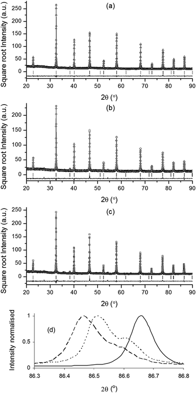 | ||
Fig. 1 Room temperature powder X-ray diffraction patterns, including results of Rietveld refinements, for as-prepared (a) La0.4Sr0.4TiO3, (b) La0.4Sr0.4Fe0.06Ti0.94O2.97 and (c) La0.4Sr0.4Ni0.06Ti0.94O2.94. (d) Overlaid 444 reflections of as-prepared (—) La0.4Sr0.4TiO3, (…) La0.4Sr0.4Fe0.06Ti0.94O2.97, and (![[dash dash, graph caption]](https://www.rsc.org/images/entities/char_e091.gif) ) La0.4Sr0.4Ni0.06Ti0.94O2.94. ) La0.4Sr0.4Ni0.06Ti0.94O2.94. | ||
| Nominal titanate composition | B-site ionic radiusa (Å) | γ | δ | E HTSE (V) | ν*e (Hz) |
|---|---|---|---|---|---|
| a Shannon radii.27 Host cation ionic radius in the case of the parent material, dopant ionic radii in the case of Ni- and Fe-doped compositions. b Inherent oxygen deficiency = (4 − n)x/2. c Indicative equilibrium oxygen deficiency introduced upon reduction in wet 5% H2/Ar at 900 °C. d Onset potential (vs. air) for high temperature steam electrolysis in 47% H2O/53% N2 at 900 °C. e Characteristic relaxation frequency for high temperature steam electrolysis in 47% H2O/53% N2 at 900 °C. | |||||
| La0.4Sr0.4TiO3 | 0.605 | 0 | 0.001 | −1.19 | 460 |
| La0.4Sr0.4Fe0.06Ti0.94O2.97 | 0.645 | 0.03 | 0.033 | −0.98 | 600 |
| La0.4Sr0.4Ni0.06Ti0.94O2.94 | 0.69 | 0.06 | 0.040 | −0.63 | 2000 |
None of the compositions showed ideal (cubic) symmetry, due to the slight tilting of TiO6 octahedra that resulted in slightly distorted perovskite crystal structures. The procedure employed for the identification of adequate crystal structures for each composition was based on indexing XRD patterns on a double cubic cell and analysing the splitting or broadening of the relevant cubic primitive reflections (e.g. the (hhh)-type (444) reflection) and the presence and type of super reflections.28–30 Using this approach, the tetragonal I4/mcm space group was assigned to the parent material, while both Fe- and Ni-doped compositions were well described by the lower symmetry monoclinic I2/a space group. The validity of space group assignments was confirmed by the good fits obtained in Rietveld refinements (see Fig. 1 and Table 2). Visualisation of La0.4Sr0.4TiO3 and La0.4Sr0.4Ni0.06Ti0.94O2.94 crystal structures was achieved using atomic positions obtained from Rietveld refinement and CrystalMaker® v.2.2.2 software (Fig. 2). The lattice distortion introduced by substituting Ni2+ for Ti4+ on the B-site was characterised by out-of-phase tilted TiO6 octahedra with respect to all axes (Fig. 2c and d), while the parent material only displayed such tilting about the z axis (Fig. 2a and b).
| Nominal titanate composition | Space group | Cell parameters (Å) | a p (Å) | Rietveld refinement parameters |
|---|---|---|---|---|
| a Pseudocubic unit cell parameter. | ||||
| La0.4Sr0.4TiO3 | I4/mcm | a = b = 5.4983, c = 7.7819 | 3.8889 | R p = 4.7, Rwp = 6.4, Re = 5.1, χ2 = 1.60 |
| La0.4Sr0.4Fe0.06Ti0.94O2.97 | I2/a | a = 7.7889, b = 5.5050, c = 5.5032, β = 90.068° | 3.8928 | R p = 5.8, Rwp = 7.6, Re = 5.0, χ2 = 2.26 |
| La0.4Sr0.4Ni0.06Ti0.94O2.94 | I2/a | a = 7.7926, b = 5.5085, c = 5.5058, β = 90.067° | 3.8949 | R p = 6.3, Rwp = 8.6, Re = 5.2, χ2 = 2.68 |
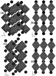 | ||
| Fig. 2 Structural representations of as-prepared (a and b) La0.4Sr0.4TiO3 (tetragonal, I4/mcm) and (c and d) La0.4Sr0.4Ni0.06Ti0.94O2.94 (monoclinic, I2/a). | ||
Higher ap values correspond to more free space within the perovskite lattice and elongated (and therefore weakened) Ti–O bonds, both of which would facilitate oxide ion mobility and therefore possibly enhance SOEC cathode performance. Even though XRD was obtained at room temperature, the order ap (Ni-doped) > ap (Fe-doped) > ap (parent) would be expected to hold at higher temperatures, since it is known that the thermal expansion of ABO3 perovskites is dominated by A–O bond expansion,31,32 and since the A-site was fixed for all compositions.
The greater thermal expansion of A–O bonds compared to B–O bonds in ABO3 perovskites means that the tolerance factor (t) (eqn (2), where rA = radius of A-site cation, rO = radius of oxide ion, and rB = radius of B-site cation) approaches unity and that the ideal cubic symmetry is attained at elevated temperatures. It is therefore likely that all of the compositions investigated here would have exhibited cubic symmetry at the principle SOEC operating temperature of 900 °C used in this study. However, while the global lattice distortion observed in titanates at room temperature would be likely absent with transition to cubic symmetry at SOEC operating temperature, it is important to recognise that the local defect chemistry and distortion in the perovskite lattice on the atomic or nano-scale would be preserved.
 | (2) |
Following reduction, room temperature XRD of all compositions over a wide 2θ range (not shown) confirmed that the perovskite structure was retained. Fig. 3 shows room temperature XRD data over different 2θ ranges for thin (∼8 μm thickness) La0.4Sr0.4Fe0.06Ti0.94O2.97 and La0.4Sr0.4Ni0.06Ti0.94O2.94 screen-printed SOEC cathodes on YSZ pellet substrates after reduction in dry 5% H2/Ar, overlaid with XRD data for as-prepared powders from Fig. 1. Over the 2θ range of 44.1–44.8°, peaks corresponding to Fe0 (Fig. 3a) and Ni0 (Fig. 3b) Fm![[3 with combining macron]](https://www.rsc.org/images/entities/char_0033_0304.gif) m (111) reflections were observed for reduced cathodes, confirming that reduction had led to the exsolution of B-site dopants in the metallic form. For both La0.4Sr0.4Fe0.06Ti0.94O2.97 and La0.4Sr0.4Ni0.06Ti0.94O2.94 cathodes, the perovskite (400) reflections over the 2θ range of 46.4–46.8° (Fig. 3c and d) shifted to lower 2θ angles with reduction, indicative of increased ap, and explained by the reduction of Ti4+ (0.605 Å) to larger Ti3+ (0.67 Å) on the B-site.
m (111) reflections were observed for reduced cathodes, confirming that reduction had led to the exsolution of B-site dopants in the metallic form. For both La0.4Sr0.4Fe0.06Ti0.94O2.97 and La0.4Sr0.4Ni0.06Ti0.94O2.94 cathodes, the perovskite (400) reflections over the 2θ range of 46.4–46.8° (Fig. 3c and d) shifted to lower 2θ angles with reduction, indicative of increased ap, and explained by the reduction of Ti4+ (0.605 Å) to larger Ti3+ (0.67 Å) on the B-site.
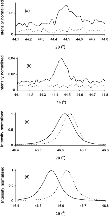 | ||
| Fig. 3 Room temperature X-ray diffraction patterns of (a and c) La0.4Sr0.4Fe0.06Ti0.94O2.97 and (b and d) La0.4Sr0.4Ni0.06Ti0.94O2.94 after reduction (—) and as-prepared (…). | ||
The case of La0.4Sr0.4Fe0.06Ti0.94O2.97 is particularly significant since this is, to our knowledge, the first report of Fe0 being exsolved from a perovskite in such a way, and represents a new approach for the generation of this industrially important catalyst. The broader significance of Fe0 exsolution may be appreciated by comparing ΔG values for the reduction of selected oxides to corresponding metals in hydrogen at 900 °C (Fig. 4). Despite the fact that the formation of Fe0 is the least thermodynamically favourable reduction indicated in Fig. 4, we consider that our targeted manipulation of defect chemistry here provided the additional driving force for the exsolution of Fe0 from the host perovskite lattice. The approach described here may be likewise applied to other dopant cations (e.g. Co2+) that are similarly less reducible compared to the cations of common transition metal catalysts (e.g. Ru4+, Rh3+, Pd2+, Pt4+), thus potentially opening a route to an array of new catalytically active perovskites with applicability well beyond the SOEC/SOFC field.
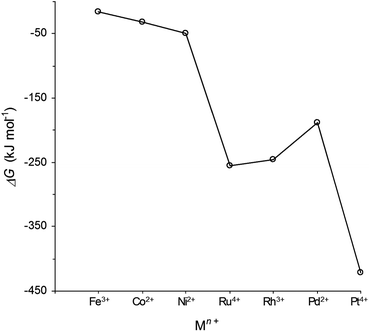 | ||
| Fig. 4 ΔG values for the reduction of selected oxides to corresponding metals in hydrogen at 900 °C (determined using HSC Chemistry 5.11 software). | ||
Particle size and BET analyses
The particle size distribution of fine titanate powders (not shown) indicated that all powders were composed primarily of ∼1 μm size particles and exhibited similar particle size distribution. This was expected since all compositions had the same A-site deficiency and therefore similar sintering behaviour, which would have resulted in similar mechanical properties. BET analysis of the same powders yielded similar SSA values of between 8.7 and 11.0 m2 g−1.In order to rule out any possible surface area effects on measured steam electrolysis properties, BET analysis was also carried out on sintered films. Similar SSA values between 4.4 and 5.6 m2 g−1 were obtained, while the average decrease in SSA in transitioning from fine powders through to sintered films was −50%, indicative of sufficient interparticle connectivity within SOEC cathodes. BET analysis confirmed that the surface area of sintered SOEC cathodes would not significantly influence SOEC testing results, so that steam electrolysis properties could be interpreted solely in terms of the dopant and defect chemistries involved.
Introduced oxygen deficiency (δ) upon reduction
Introduced oxygen deficiency (δ) is an equilibrium measure of the extent of reduction and is determined by material properties and experimental pO2 and temperature conditions. Reduction of porous titanate pellets of similar porosity to screen-printed electrolysis cell cathodes at 900 °C in wet 5% H2/Ar and measurement of sample masses before and after reduction revealed indicative δ values of 0.001, 0.033 and 0.040 (values ±0.001) for La0.4Sr0.4TiO3, La0.4Sr0.4Fe0.06Ti0.94O2.97 and La0.4Sr0.4Ni0.06Ti0.94O2.94, respectively (note that actual δ values would be higher due to lower pO2 under SOEC operating conditions (e.g. pO2 = 3.3 × 10⁻²⁷ at −1.5 V applied potential) compared to wet 5% H2/Ar (pO2 = 1.9 × 10⁻¹⁷). The magnitude of δ is important since it correlates with the concentration of Ti3+ (3d1) electron carriers (eqn (1)) and determines, together with inherent oxygen deficiency (γ), total oxygen deficiency (γ + δ). As a result the magnitude of δ governs the electronic conductivity of titanates33 and determines the number of vacant sites available for oxide ion migration and also likely determines the availability of sites for the adsorption of reactant steam molecules during steam electrolysis. Indicative (γ + δ) values for La0.4Sr0.4TiO3, La0.4Sr0.4Fe0.06Ti0.94O2.97 and La0.4Sr0.4Ni0.06Ti0.94O2.94 were 0.001, 0.063 and 0.100, respectively, suggesting that B-site doping of the parent material in general, and especially in the case of Ni2+, would likely yield increased oxide ion mobility, electronic conductivity and availability of adsorption sites.Visualisation of exsolved metallic nanoparticles on titanate substrates
Fig. 5 presents SEM images of tested B-site doped perovskite SOEC cathodes collected using a backscattered electron detector to reveal compositional contrast. The unevenly distributed bright spots on the surface represent metallic exsolutions, which is consistent with the XRD evidence of metallic exsolutions in reduced B-site doped titanates (Fig. 3). The uneven distribution of exsolutions was likely due to the predominant A-site termination of grains, since surface analysis of perovskites has generally indicated A/B ratios exceeding unity.34–36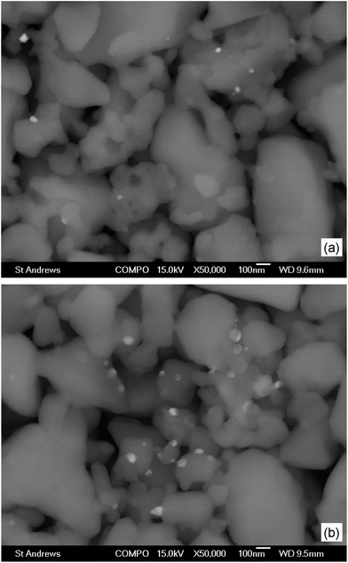 | ||
| Fig. 5 Scanning electron micrographic (SEM) images of (a) La0.4Sr0.4Fe0.06Ti0.94O2.97 and (b) La0.4Sr0.4Ni0.06Ti0.94O2.94 tested electrolysis cell cathodes. Images were collected using a backscattered electron detector for compositional contrast. | ||
The Ni0 exsolutions observed on the surface of La0.4Sr0.4Ni0.06Ti0.94O2.94 (Fig. 5b) were generally larger (∼60 to 90 nm) and more numerous compared to the Fe0 exsolutions (∼30 to 60 nm) observed on the surface of La0.4Sr0.4Fe0.06Ti0.94O2.97 (Fig. 5a). These observations may be explained by considering a combination of exsolution driving forces relating to the charge, ionic radius and reducibility of the dopant (since the driving force due to A-site deficiency is the same in both cases). Consideration of dopant relative charges reveals a higher inherent oxygen deficiency for the Ni2+-doped composition (γ = 0.06) compared to the Fe3+-doped composition (γ = 0.03), suggesting a higher exsolution driving force for the former. A similar suggestion is arrived at by considering the larger ion size mismatch between Ni2+ (0.69 Å) and Ti4+ (0.605 Å) compared to that between Fe3+ (0.645 Å) and Ti4+, which would have likely resulted in greater local lattice distortion and strain in the case of the former. Finally, the relative number of exsolutions might also be explained by the greater ease of reduction of Ni2+ compared to Fe3+ (Fig. 4).
Proposed exsolution mechanism
A proposed mechanism for B-site dopant exsolution from A-site deficient titanates during SOEC operation is described in Fig. 6. Initially the as-prepared, oxidised titanate is reduced, introducing oxygen vacancies (δ)(step 1). Reduction continues until a limit in the number of introduced oxygen vacancies (δlim) is reached (step 2). At this point the titanate lattice is unable to accommodate any more vacancies, and continued reduction results in exsolution of a proportion (ξ) of the B-site dopant and its simultaneous reduction to metal (step 3). Our previous investigations on the series with M = Ga3+ and 0 ≤ x ≤ 0.15 suggested that such an exsolution step is likely to be restricted to the titanate surface, while the bulk stoichiometry remains unchanged, and roughly half of the initial dopant exsolves under similar conditions to those used in this study.25 Finally, the product perovskite at the surface after step 3 is equivalent to a locally stabilised perovskite lattice with full B-site occupancy and raised A-site and oxygen occupancy.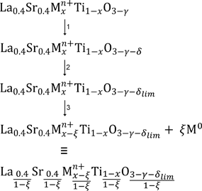 | ||
| Fig. 6 Proposed mechanism of B-site dopant exsolution from A-site deficient titanates under electrolysis cell operating (reducing) conditions. | ||
From Fig. 6 an example of surface perovskite stoichiometry obtained after SOEC operation and subsequent exsolution of B-site dopant may be considered, where M = Ni2+, x = 0.06 and γ = 0.06. We have observed experimentally that exsolutions generally occur in a reasonable number above a certain threshold in δ of ∼0.05, which may be taken as the value for δlim in this example. An accurate experimental value for ξ is difficult to obtain, so for the purpose of this example we may assume that half of the B-site dopant is exsolved from the surface, giving ξ = 0.03. Substitution of x, γ, δlim and ξ values yields La0.412Sr0.412Ni0.031Ti0.969O2.979, which is characterised by increased A-site and oxygen occupancy and a decrease in the proportion of Ni2+ on the B-site compared to the starting composition, La0.4Sr0.4Ni0.06Ti0.94O2.94. The increased stability and ease in local lattice distortion and strain at the surface compared to the starting composition help to explain firstly why the B-site dopant was exsolved from the lattice during SOEC operation, and secondly why the exsolution of B-site dopants from the La0.4Sr0.4Mn+xTi1−xO3−γ−δ system was not totally reversible, as indicated by the continued presence of surface exsolutions after 12 h re-oxidation in air at 1000 °C.
Steam electrolysis using B-site doped titanate cathodes
The I–V characteristics of SOECs based on La0.4Sr0.4TiO3, La0.4Sr0.4Fe0.06Ti0.94O2.97 and La0.4Sr0.4Ni0.06Ti0.94O2.94 cathodes were evaluated in 47% H2O/53% N2 at 900 °C (Fig. 7). B-site doping resulted in enormous drops in the (absolute) HTSE onset potential (EHTSE), from −1.19 V for the parent material to −0.98 V and −0.63 V for Fe- and Ni-doped compositions, respectively. EHTSE reflects the activation barrier to steam electrolysis, and was determined by extrapolating the ohmic (linear) segment of I–V curves to zero current. The differences in the activation barrier may be better appreciated by considering the same I–V data at low current densities (Fig. 7b). Reading the I–V data from zero to higher (absolute) current densities (i.e. from right to left), activation of La0.4Sr0.4TiO3 was observed to take place over a relatively wide range of applied potential, before the I–V curve entered into the ohmic regime (indicated by the fitted straight lines). In contrast, a significantly narrowed applied potential range was required before the response of La0.4Sr0.4Fe0.06Ti0.94O2.97 became ohmic, while La0.4Sr0.4Ni0.06Ti0.94O2.94 was activated into the ohmic regime over a greatly narrowed applied potential range. Encouragingly, EHTSE for the La0.4Sr0.4Ni0.06Ti0.94O2.94-based SOEC was the same as that for an in-house SOEC based on state-of-the-art Ni/YSZ, adding to above evidence for the presence of exsolved metallic Ni on the perovskite surface.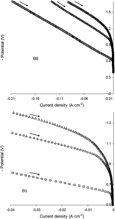 | ||
| Fig. 7 Current–voltage (I–V) curves obtained for (△) La0.4Sr0.4TiO3, (◇) La0.4Sr0.4Fe0.06Ti0.94O2.97 and (□) La0.4Sr0.4Ni0.06Ti0.94O2.94 electrolysis cell cathodes operated in 47% H2O/53% N2 at 900 °C (a) complete data (b) focus on low current density. Fitted straight lines in (b) indicate ohmic regime of electrolysis cell operation. | ||
According to the crystallographic, gravimetric and microstructural evidence presented in earlier sections, the lowered steam electrolysis activation barrier observed in Fig. 7 for B-site doped compositions compared to the parent material can be ascribed to the exsolution of electrocatalytically active metallic nanoparticles and higher oxygen vacancy concentrations. Furthermore the significantly superior steam electrolysis performance of Ni0-bearing La0.4Sr0.4Ni0.06Ti0.94O2.94 compared to Fe0-bearing La0.4Sr0.4Fe0.06Ti0.94O2.97 was not surprising given that Ni0 (combined with YSZ) is the best known electrocatalyst for steam electrolysis.37 Indicative total (γ + δ) oxygen deficiency (Table 1) was also a contributing factor. La0.4Sr0.4Ni0.06Ti0.94O2.94 showed higher γ + δ value (0.100) compared to La0.4Sr0.4Fe0.06Ti0.94O2.97 (0.063), most likely yielding increased oxide ion mobility and availability of adsorption sites in the former. Just as importantly, La0.4Sr0.4Ni0.06Ti0.94O2.94 demonstrated higher indicative δ (0.040) compared to La0.4Sr0.4Fe0.06Ti0.94O2.97 (0.033), which would likely have resulted in enhanced electronic conductivity in the former due to the higher concentration of Ti3+ (3d1) electron carriers (eqn (1)). Overall, calculated γ values and measured δ values suggested enhanced MIEC properties for La0.4Sr0.4Ni0.06Ti0.94O2.94 compared to La0.4Sr0.4Fe0.06Ti0.94O2.97, which would have contributed to the superior steam electrolysis performance of the former.
The outright steam electrolysis performance of the La0.4Sr0.4Ni0.06Ti0.94O2.94 cathode was a significant step-change compared to other perovskites considered to date, although the results of EIS analysis presented below indicate that the performance of this material is still lacking compared to state-of-the-art Ni/YSZ. However, the approach pursued here has at least two distinct advantages. Firstly, it is likely that Ni0 exsolutions from La0.4Sr0.4Ni0.06Ti0.94O2.94 would be stable and resistant to agglomeration under SOEC operating conditions since we have observed that such exsolutions did not cluster after prolonged (100 h) exposure in wet 5% H2/Ar at 900 °C, as if pinned to the surface, although stability in a high steam environment is yet to be confirmed and is beyond the scope of this study. A general note of caution should also be made here since ripening of metallic exsolutions on perovskite SOFC anodes has been observed on occasion, depending on the particular chemistries involved.12,15,17 Secondly, perovskites offer an enormous number of compositional possibilities due to their ability to accept similarly sized isovalent or aliovalent cations in place of host A-site and/or B-site cations. This provides significant scope for the improvement of perovskite SOEC cathode properties via the targeted tuning of dopant and defect chemistries beyond what is considered in this study.
SOECs were also evaluated by measuring I–V curves in 47% H2O/3% H2/50% N2 at 900 °C in order to observe properties in a reactant stream containing hydrogen (Fig. 8). In SOEC mode (I < 0), the relative cathode properties were similar to those observed when hydrogen was absent from the reactant stream (Fig. 7). The I–V data for La0.4Sr0.4TiO3 and La0.4Sr0.4Fe0.06Ti0.94O2.97 were characterised by curvature, indicative of deactivation, that commenced in SOEC mode and continued through into SOFC mode (I > 0), resulting in dismal SOFC performance for these compositions. In contrast, the I–V data for La0.4Sr0.4Ni0.06Ti0.94O2.94 were essentially ohmic across SOEC and SOFC modes, suggesting that this material may also be promising for reversible SOEC/SOFC units as part of a grid energy storage system. The promising performance of La0.4Sr0.4Ni0.06Ti0.94O2.94 in SOFC mode is not surprising since the composite of Ni0 and YSZ constitutes the state-of-the-art in SOFC anode materials.
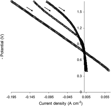 | ||
| Fig. 8 Current–voltage (I–V) curves obtained for (△) La0.4Sr0.4TiO3, (◇) La0.4Sr0.4Fe0.06Ti0.94O2.97 and (□) La0.4Sr0.4Ni0.06Ti0.94O2.94 electrolysis cell cathodes operated in 47% H2O/3% H2/50% N2 at 900 °C. | ||
The frequency-dependent steam electrolysis properties of SOECs based on La0.4Sr0.4TiO3, La0.4Sr0.4Fe0.06Ti0.94O2.97 and La0.4Sr0.4Ni0.06Ti0.94O2.94 cathodes were evaluated in 47% H2O/53% N2 at 900 °C at −1.5 V applied potential (Fig. 9). EIS data were fitted using equivalent circuits, with the results of fitting indicated by lines. For the parent material, the EIS data were best fitted using a L-Rs-(Rp1||CPE1)-(Rp2||CPE2) equivalent circuit, while a simpler L-Rs-(Rp||CPE) equivalent circuit resulted in good fits to the EIS data for La0.4Sr0.4Ni0.06Ti0.94O2.94 and La0.4Sr0.4Fe0.06Ti0.94O2.97 (L = inductance, Rs = series resistance, Rp = polarisation resistance, CPE = constant phase element). Equivalent circuits were fitted to the predominant impedance arc and high frequency responses only due to insufficient data at low frequencies and in order to maintain the quality of fits.
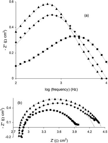 | ||
| Fig. 9 Electrochemical impedance spectroscopy (EIS) analysis of (▲) La0.4Sr0.4TiO3, (◆) La0.4Sr0.4Fe0.06Ti0.94O2.97 and (■) La0.4Sr0.4Ni0.06Ti0.94O2.94 electrolysis cell cathodes operated in 47% H2O/53% N2 at 900 °C at −1.5 V applied potential. (a) Bode and (b) Nyquist plots. Lines indicate results of equivalent circuit fitting. | ||
B-site doping resulted in dramatic increases in characteristic relaxation frequency (ν*) as shown in the Bode plots in Fig. 9a, where ν* reflects the timescale of the steam electrolysis limiting process and was taken as the frequency at maximum (absolute) imaginary impedance (Z′′).38 We have previously observed increases in ν* for A-site deficient and oxygen excess (La,Sr)TiO3 SOEC cathodes with the addition of the known oxide ion conductor YSZ, leading to the suggestion that ν* largely reflects oxide ion mobility in such cathode materials.4 Values for ν* increased from 460 Hz for La0.4Sr0.4TiO3 to 600 Hz and 2 kHz for La0.4Sr0.4Fe0.06Ti0.94O2.97 and La0.4Sr0.4Ni0.06Ti0.94O2.94, respectively (Table 1). The trend in ν* was somewhat reflected in Rp, with a significant improvement from 1.7 Ω cm2 for the parent material to 1.5 Ω cm2 and 1.2 Ω cm2 for Fe- and Ni-doped compositions, respectively.
The results of EIS analysis presented in Fig. 9 may be interpreted similarly to the way in which the results of I–V testing were above. That is, B-site doping of the parent material led to improvements in ν* and Rp, roughly consistent with indicative total (γ + δ) and introduced (δ) oxygen deficiency, and therefore likely increased oxide ion mobility, electronic conductivity and availability of adsorption sites. The significantly improved ν* observed for La0.4Sr0.4Ni0.06Ti0.94O2.94 compared to La0.4Sr0.4Fe0.06Ti0.94O2.97 in particular might also be related to the fact that Ni0, exsolved from the former composition during SOEC operation, is the best-known electrocatalyst for steam electrolysis when combined with YSZ.
Temperature dependence of La0.4Sr0.4Ni0.06Ti0.94O2.94 electrolysis cell cathode
The steam electrolysis properties of La0.4Sr0.4TiO3, La0.4Sr0.4Fe0.06Ti0.94O2.97 and La0.4Sr0.4Ni0.06Ti0.94O2.94 SOEC cathodes on cooling between 900 and 700 °C in 47% H2O/53% N2 were all evaluated, however only the Ni-doped composition displayed different characteristics depending on the temperature. Fig. 10a shows the I–V curves measured for an SOEC based on a La0.4Sr0.4Ni0.06Ti0.94O2.94 cathode in 47% H2O/53% N2 between 900 and 700 °C at 50 °C intervals. At 900 °C the I–V response was purely ohmic, however at temperatures below 900 °C, I–V curves were Z-shaped with kinks observed between −1.0 V and −1.3 V applied potential, corresponding to a transition between non-ohmic and ohmic regimes in the direction of measurement. When the logarithm of the potential at which these non-ohmic to ohmic transitions took place (Enon-ohmic↔ohmic) was plotted as a function of reciprocal temperature (Fig. 10b), a linear dependence was observed, demonstrating that the transition was thermally activated with an activation energy (Ea) of 0.12 eV.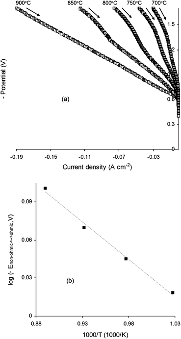 | ||
| Fig. 10 (a) Current–voltage (I–V) curves measured on cooling between 900 and 700 °C for a La0.4Sr0.4Ni0.06Ti0.94O2.94 electrolysis cell cathode operated in 47% H2O/53% N2. (b) Logarithm of transition potential between non-ohmic and ohmic regimes plotted against reciprocal temperature for electrolysis cell operating temperatures <900 °C. | ||
The temperature dependence of La0.4Sr0.4Ni0.06Ti0.94O2.94 was further investigated by performing EIS analysis on cooling over the slightly expanded temperature range of 920–700 °C in 47% H2O/53% N2. Importantly, EIS analysis was carried out at an applied potential of −1.5 V, which would have corresponded to the non-ohmic regime observed in the I–V curves in Fig. 10a for temperatures between 850 and 700 °C (inclusive). Fig. 11 shows the plots of the logarithm of ν* against reciprocal temperature for all compositions. In the case of La0.4Sr0.4Ni0.06Ti0.94O2.94, the temperature dependence of ν* was seemingly split about a critical transition temperature of 850 °C into high and low temperature regions characterised by Ea values of 2.09 eV and 0.92 eV, respectively. Such split behaviour was broadly consistent with the temperature dependence of the I–V properties observed for La0.4Sr0.4Ni0.06Ti0.94O2.94 in Fig. 10a, and suggested that different steam electrolysis limiting processes were dominant at high and low temperatures. In contrast to La0.4Sr0.4Ni0.06Ti0.94O2.94, the temperature dependence of La0.4Sr0.4TiO3 and La0.4Sr0.4Fe0.06Ti0.94O2.97 was monotonous, with Ea values of 0.99 eV and 0.87 eV, respectively. These Ea values were similar to that observed for La0.4Sr0.4Ni0.06Ti0.94O2.94 in the low temperature region (0.92 eV), suggesting the same steam electrolysis limiting process.
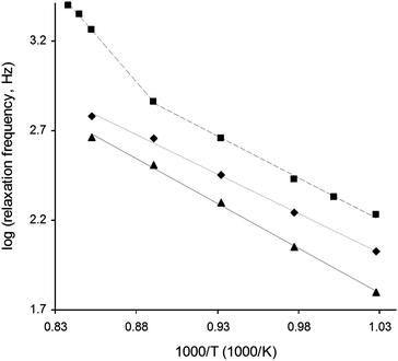 | ||
| Fig. 11 Logarithm of relaxation frequency plotted against reciprocal temperature for (▲) La0.4Sr0.4TiO3, (◆) La0.4Sr0.4Fe0.06Ti0.94O2.97 and (■) La0.4Sr0.4Ni0.06Ti0.94O2.94 electrolysis cell cathodes. Measurements were performed on cooling in 47% H2O/53% N2 at −1.5 V applied potential. | ||
Beyond the simple description of temperature dependence provided above, a satisfactory explanation of observed phenomena is not possible with our current understanding of these materials and without resorting to unsubstantiated speculation in the absence of additional evidence. In future we seek to arrive at a satisfactory explanation as we gather data on and learn more about related compositions.
Conclusions
Modest B-site doping of La0.4Sr0.4TiO3 with Fe3+ or Ni2+ led to step-changes in steam electrolysis performance brought about by the exsolution of electrocatalytically active metallic nanoparticles and likely higher oxygen vacancy concentrations. The best performing material, La0.4Sr0.4Ni0.06Ti0.94O2.94, demonstrated significant and similar performance in both SOEC and SOFC modes, making this material a candidate for reversible SOEC/SOFC units for grid energy storage systems. While the progress demonstrated in this study is significant, future improvements are anticipated due to the ability to specifically tune perovskite properties for steam electrolysis via prudent selection of dopant and defect chemistries.Acknowledgements
We thank the Research Councils UK Energy Programme for support of the Delivery of Sustainable Hydrogen Supergen project which funded this research.Notes and references
- O. A. Marina, L. R. Pederson, M. C. Williams, G. W. Coffey, K. D. Meinhardt, C. D. Nguyen and E. C. Thomsen, J. Electrochem. Soc., 2007, 154, B452–B459 CrossRef CAS
.
- X. Yang and J. T. S. Irvine, J. Mater. Chem., 2008, 18, 2349–2354 RSC
.
- Q. Liu, C. Yang, X. Dong and F. Chen, Int. J. Hydrogen Energy, 2010, 35, 10039–10044 CrossRef CAS
.
- G. Tsekouras and J. T. S. Irvine, J. Mater. Chem., 2011, 21, 9367–9376 RSC
.
- C. Jin, C. Yang, F. Zhao, D. Cui and F. Chen, Int. J. Hydrogen Energy, 2011, 36, 3340–3346 CrossRef CAS
.
- G. Corre, G. Kim, M. Cassidy, J. M. Vohs, R. J. Gorte and J. T. S. Irvine, Chem. Mater., 2009, 21, 1077–1084 CrossRef CAS
.
- C.-D. Savaniu and J. T. S. Irvine, J. Mater. Chem., 2009, 19, 8119–8128 RSC
.
- J.-S. Kim, N. L. Wieder, A. J. Abraham, M. Cargnello, P. Fornasiero, R. J. Gorte and J. M. Vohs, J. Electrochem. Soc., 2011, 158, B596–B600 CrossRef CAS
.
- C. Perillat-Merceroz, G. Gauthier, P. Roussel, M. Huve, P. Gelin and R.-N. Vannier, Chem. Mater., 2011, 23, 1539–1550 CrossRef CAS
.
- Y. Nishihata, J. Mizuki, T. Akao, H. Tanaka, M. Uenishi, M. Kimura, T. Okamoto and N. Hamada, Nature, 2002, 418, 164–167 CrossRef CAS
.
- H. Tanaka, M. Uenishi, M. Taniguchi, I. Tan, K. Narita, M. Kimura, K. Kaneko, Y. Nishihata and J. Mizuki, Catal. Today, 2006, 117, 321–328 CrossRef CAS
.
- B. D. Madsen, W. Kobsiriphat, Y. Wang, L. D. Marks and S. A. Barnett, ECS Trans., 2007, 7, 1339–1348 CrossRef CAS
.
- B. D. Madsen, W. Kobsiriphat, Y. Wang, L. D. Marks and S. A. Barnett, J. Power Sources, 2007, 166, 64–67 CrossRef CAS
.
- W. Kobsiriphat, B. D. Madsen, Y. Wang, L. D. Marks and S. A. Barnett, Solid State Ionics, 2009, 180, 257–264 CrossRef CAS
.
- W. Kobsiriphat, B. D. Madsen, Y. Wang, M. Shah, L. D. Marks and S. A. Barnett, J. Electrochem. Soc., 2010, 157, B279–B284 CrossRef CAS
.
- T. Jardiel, M. T. Caldes, F. Moser, J. Hamon, G. Gauthier and O. Joubert, Solid State Ionics, 2010, 181, 894–901 CrossRef CAS
.
- D. M. Bierschenk, E. Potter-Nelson, C. Hoel, Y. Liao, L. Marks, K. R. Poeppelmeier and S. A. Barnett, J. Power Sources, 2011, 196, 3089–3094 CrossRef CAS
.
- L. Adijanto, V. B. Padmanabhan, R. Kungas, R. J. Gorte and J. M. Vohs, J. Mater. Chem., 2012, 22, 11396–11402 RSC
.
- J. R. Mawdsley and T. R. Krause, Appl. Catal., A, 2008, 334, 311–320 CrossRef CAS
.
- M. D. Smith, A. F. Stepan, C. Ramarao, P. E. Brennan and S. V. Ley, Chem. Commun., 2003, 2652–2653 RSC
.
- O. A. Marina, N. L. Canfield and J. W. Stevenson, Solid State Ionics, 2002, 149, 21–28 CrossRef CAS
.
- A. Atkinson, S. Barnett, R. J. Gorte, J. T. S. Irvine, A. J. McEvoy, M. Mogensen, S. C. Singhal and J. Vohs, Nat. Mater., 2004, 3, 17–27 CrossRef CAS
.
- M. S. Islam, Solid State Ionics, 2002, 154–155, 75–85 CrossRef CAS
.
- A. Jones and M. S. Islam, J. Phys. Chem. C, 2008, 112, 4455–4462 CAS
.
- D. Neagu and J. T. S. Irvine, Chem. Mater., 2011, 23, 1607 CrossRef CAS
.
- J. C. Ruiz-Morales, J. Canales-Vazquez, C. Savaniu, D. Marrero-Lopez, W. Zhou and J. T. S. Irvine, Nature, 2006, 439, 568–571 CrossRef CAS
.
- R. Shannon, Acta Crystallogr., Sect. A: Found. Crystallogr., 1976, 32, 751–767 CrossRef
.
- A. M. Glazer, Acta Crystallogr., Sect. B: Struct. Crystallogr. Cryst. Chem., 1972, 28, 3384–3392 CrossRef CAS
.
- C. J. Howard and H. T. Stokes, Acta Crystallogr., Sect. B: Struct. Sci., 1998, 54, 782–789 CrossRef
.
- C. J. Howard and H. T. Stokes, Acta Crystallogr., Sect. A: Found. Crystallogr., 2005, 61, 93–111 CrossRef
.
-
J. B. Goodenough, in Structure and Bonding, ed. J. B. Goodenough, Springer, Berlin, 2001, pp. 1–16 Search PubMed
.
- B. Dabrowski, O. Chmaissem, J. Mais, S. Kolesnik, J. D. Jorgensen and S. Short, J. Solid State Chem., 2003, 170, 154–164 CrossRef CAS
.
- D. Neagu and J. T. S. Irvine, Chem. Mater., 2010, 22, 5042–5053 CrossRef CAS
.
- Z. Cai, Y. Kuru, J. W. Han, Y. Chen and B. Yildiz, J. Am. Chem. Soc., 2011, 133, 17696–17704 CrossRef CAS
.
- Y. Chen, W. C. Jung, Y. Kuru, H. Tuller and B. Yildiz, ECS Trans., 2011, 35, 2409–2416 CrossRef CAS
.
- J. W. Han, H. Jalili, Y. Kuru, Z. Cai and B. Yildiz, ECS Trans., 2011, 35, 2097–2104 CrossRef CAS
.
- S. H. Jensen, P. H. Larsen and M. Mogensen, Int. J. Hydrogen Energy, 2007, 32, 3253–3257 CrossRef CAS
.
- A. Bieberle, L. P. Meier and L. J. Gauckler, J. Electrochem. Soc., 2001, 148, A646–A656 CrossRef CAS
.
| This journal is © The Royal Society of Chemistry 2013 |
