Development of bilayer and trilayer nanofibrous/microfibrous scaffolds for regenerative medicine
Frazer J. Byea, Julio Bissolia, Leanne Blacka, Anthony J. Bullocka, Sasima Puwanuna, Keyvan Moharamzadehb, Gwendolen C. Reillya, Anthony J. Ryanc and Sheila MacNeil*a
aKroto Research Institute, University of Sheffield, Broad Lane, Sheffield, South Yorkshire S7 1LN, United Kingdom. E-mail: s.macneil@sheffield.ac.uk; Fax: +44 (0) 114 222 5943; Tel: +44 (0) 114 222 5995
bAcademic Unit of Restorative Dentistry, The School of Clinical Dentistry, The University of Sheffield, Claremont Crescent, Sheffield, S10, 2TA, United Kingdom. E-mail: k.moharamzadeh@sheffield.ac.uk; Fax: +44 (0) 114 226 5484; Tel: +44 (0) 114 271 7931
cDepartment of Chemistry, University of Sheffield, Sheffield, S3 7HF, United Kingdom. E-mail: a.ryan@sheffield.ac.uk; Fax: +44 (0) 114 222 9346; Tel: +44 (0) 114 222 9300
First published on 3rd June 2013
Abstract
Many biomaterial scaffolds have been developed for use in tissue engineering usually for populating with a single cell-type. In this study we demonstrate the production of bilayer and trilayer nanofibrous/microfibrous biodegradable scaffolds suitable for the support, proliferation and yet segregation of different tissues – here used to separate soft tissue from bone forming tissue and keratinocytes from fibroblasts. Essentially we describe a nanofibre barrier membrane which is permeable to nutrients coupled with attached microfibers (either on one side or both sides) to support the proliferation of different cell types either side but prevents migration of cells across the barrier. Such membranes would be suitable for guided tissue regeneration in areas where one wishes to support both soft and hard tissues but keep them separated. We describe a sterile bilayer membrane electrospun from polyhydroxybutyrate-co-hydroxyvalerate (PHBV) (nanofibres) and polylactic acid (PLA) or poly ε-caprolactone (PCL) (microfibres) and a trilayer membrane electrospun in layers of PLA, PHBV, then PLA. These membranes are biocompatible, biodegradable and capable of supporting two different cell populations.
Introduction
Biomaterial scaffolds are extensively used as carriers for cells and as 3D scaffolds for the regeneration of new tissue. They are commonly tailored to specific tissue types. Thus they are designed to have the necessary mechanical properties for the tissue that they are seeking to repair or replace. All scaffolds must be biocompatible to avoid provoking an adverse immune response to be successful post-implantation. The majority of scaffolds (but not all) are designed to be biodegradable with the intention that cells introduced in the scaffolds will form a new tissue and supporting tissue matrix, replacing the implanted scaffold as it degrades, for a long term successful repair. Biodegradable devices also negate the necessity for a second surgical operation to remove the implant.1 There are many polymers that can be used to create a biocompatible and degradable implant.2,3The ultimate goal of tissue engineering is to be able to regenerate or replace diseased or damaged tissues.4,5 Tissue engineering, based on autologous laboratory expanded cells and scaffolds, is most commonly used but sometimes scaffolds are designed to promote the in growth of the surrounding tissue in vivo.6,7 Here the approach is essentially to concentrate on using the patient's own tissues in conjunction with scaffolds to regenerate the areas in need of repair.8–12
Thus in tissue engineering very often the patient's own tissues are biopsied, cells expanded in the laboratory and combined with scaffolds to regenerate tissues for repair of damaged areas. However there are many conditions when one needs to look at replacing both soft tissues and adjacent hard tissues or to introduce a scaffold that could promote the intrinsic repair of soft tissues and hard tissues.13,14
While it is entirely possible to culture skin cells or even epithelia it has been difficult to make more complex tissues. The last decade has seen a growing realisation that the 3D environment of the extracellular matrix in which cells live is far from passive. Not only are the cells receiving signals from the extracellular matrix proteins but the composition of the matrix and it's stiffness give major signals which guide the differentiation and performance of cells within this matrix.15 Thus bone was originally repaired using metal splints, providing the structural and mechanical support while allowing the bone to heal.16 There are now ceramics and osteoinductive materials which can be used to aid bone repair. Tissue guidance membranes have been developed, for example for use in periodontal defects seeking to achieve guided tissue regeneration.17–19 The problem of one tissue growing much faster than another, invading and preventing the appropriate expansion of the slower growing tissue needs to be considered.
One area where tissues require segregation is in the treatment of cleft palate. This condition affects 1 in every 500–700 live births worldwide.20 The current standard treatment is protracted, involving many stages. While soft tissue defects can be readily repaired within a few months, defects of the hard tissue of the alveolar ridge (which bears teeth) and the hard palate are much more challenging. After birth a cleft lip is repaired at 3 months, and then the defect in the hard palate is covered with soft tissue at around 1 year. This results in the child having to use custom made acrylic moulded prosthesis known as an obturator.
Bone grafts to fill the hard palate defect are currently not used as an option as they have actually been found to lead to distortion of the maxilla and the results can be worse than no surgery.21,22 Bone grafts appear to be satisfactory, immediately after implantation, but then the bone cells fuse and this tissue does not grow at the rate of the child's head causing major facial disfigurement. The subsequent complications and distortions to the maxilla are unacceptable and explain why the hard tissues of the palate are currently mostly left untreated and an obturator used.
The problem of treating hard tissue defects in the cleft palate is twofold. Firstly, hard tissues grow at a rate far slower than soft tissue. An implant must account for this and prevent the invasion of the much faster growing soft tissues into regions where the hard tissues are desired. The implant must also allow for the flow of nutrients in order to allow the separated tissues to proliferate. Secondly, the implant must be compatible with the growth of the patient. The area of a cleft defect approximately doubles in volume from birth to the age of 5 and this must be taken into consideration in developing materials and procedures for treatment of hard palate defects.23,24 The implant must also be biocompatible and biodegradable as it would be undesirable to remove an implant at a later stage disturbing the new tissues and risking the formation of disfiguring scar tissue.
An ideal solution would be an approach that could treat both soft and hard palate defects early in the child's life requiring very minimal follow up. We emphasise that we are not aware of any such solution on the horizon at present. To achieve an early stage repair for soft and hard palate, the biomaterial to be introduced must be able to cope with the dramatic growth of the child's palate up to the age of five. For bone to form it is highly likely that bone forming tissue or cells will need to be introduced into the defect; one common source for similar surgery are bone chips from the femoral head. It would be quite possible to culture bone forming cells (bone marrow MSC for example) on a scaffold for use in the hard palate. However introduction of soft tissue, such as tissue engineered buccal mucosa or in growth of soft tissues from the periphery of the defect could threaten the development of hard palate tissues as soft tissues will grow throughout such a scaffold almost certainly forming a fibrotic scar. Scar tissue can contract extensively, distorting the growth of the palate, hence one requirement in developing materials for treatment of soft and hard palate defects is a biocompatible and resorbable tissue segregating membrane which should separate and yet still allow the proliferation of soft tissues on one side and hard tissues on the other without allowing in growth of soft tissues into the hard palate area.
A second area is tissue engineering of skin for burns or diabetic ulcer repair. A biopsy of healthy skin is taken, cultured and expanded in the laboratory on a scaffold ready for implantation back on the patient. Normally in the laboratory we culture keratinocytes under long-established conditions using murine fibroblast feeder cells and media with bovine foetal calf serum.25 However, for use in the clinic, it would be preferable to achieve keratinocyte culture without the need for any animal products and the chance of viral or prion infection they may bring. We have had some success previously, using autologous fibroblast feeder cells (instead of murine cells) and omitting bovine serum in the initial expansion of keratinocytes.26,27 Building on this a scaffold designed to provide a synthetic basement membrane would be advantageous as it would give the cells a framework around which to start producing the required extracellular matrix. If the scaffold was designed to be porous, fibroblasts cultured on the lower surface could act as a feeder layer, and culture may be achieved without the need for animal products.
With respect to choice of scaffolds, PHBV was selected for use as a barrier membrane due to its slow degradation time and ease of synthesis through phosphate starving the bacteria Alcaligene eutrophus.28–30 Toxicological assessment of the polymer in vitro and in vivo has shown no negative effects or abnormalities when tested with cultured cells or in animal experiments and it has been patented for use as bioresorbable sutures.31–33 Poly L-lactic acid is well known as a biodegradable biomaterial with good biocompatibility.2,34–38 It has been used for several years in the MacNeil group and a knowledge base has been established, making it a good candidate for further investigation.39,40 PCL was included in this study as it has been successfully used as a scaffold for production of bone, as extensively reviewed by Woodruff and Hutmacher.41–45 We have experience of culturing autologous buccal mucosa based on de-epidermised acellular human dermis, and of taking this to the clinic for replacing scarred tissue of the urethra.13,14,46 We also have previously developed synthetic electrospun scaffolds for soft tissue reconstruction.40,47
Against this background; our approach to designing a tissue barrier membrane is to harness electrospinning to produce bilayer and trilayer nanofibrous/microfibrous scaffolds suitable for separating and independent proliferation of two distinct tissue types such as soft tissue on one side and bone tissue on the other side. These scaffolds are designed for culturing a range of tissues under different situations. Thus we describe a bilayer structure made to segregate bone and soft tissues. We describe a trilayer structure intended to support soft tissue growth either side. For example two populations of cells such as epithelial and stromal cells as shown here, require an open network (microfibers) to grow into but still require segregation (nanofibres). These scaffolds are also designed to be capable of plastic deformation so that they can grow with the growth of the child's skull.48 These scaffolds are the first step towards developing a synthetic solution to tissue separation.
Methods and materials
Electrospinning of PHBV, PCL, and PLA monolayers
All electrospinning was conducted in an aseptic cleanroom environment.10 wt% PLA, PCL (Sigma Aldrich, Dorset, UK) solutions were made by dissolving the bulk polymer in dichloromethane (DCM, Sigma Aldrich, Dorset, UK). 10 wt% PHBV (12![[thin space (1/6-em)]](https://www.rsc.org/images/entities/char_2009.gif) :1 PHB–PHV, Goodfellow, Huntingdon, UK) solutions were made by dissolving the bulk polymer in a mixed solvent of 10 wt% methanol and 80 wt% DCM (solvent ratio 88.8:11.1 DCM–MeOH, Sigma Aldrich). These solutions were loaded into 4 × 5 ml syringes (20 ml in total), fitted with blunt-tip needles (0.6 mm ID), and placed onto a single syringe pump (40 μL min−1, Genie Plus, Kent Scientific, Connecticut, USA). A mandrel, 20 cm wide and 10 cm in diameter, coated in aluminium foil and rotated at 200 rpm, was used to collect the fibres. A working distance of 17 cm from the needle tip to the mandrel was used for PLA and PCL and 10 cm for PHBV. A potential of +17000 V was used (73030P, Genvolt, Shropshire UK).
:1 PHB–PHV, Goodfellow, Huntingdon, UK) solutions were made by dissolving the bulk polymer in a mixed solvent of 10 wt% methanol and 80 wt% DCM (solvent ratio 88.8:11.1 DCM–MeOH, Sigma Aldrich). These solutions were loaded into 4 × 5 ml syringes (20 ml in total), fitted with blunt-tip needles (0.6 mm ID), and placed onto a single syringe pump (40 μL min−1, Genie Plus, Kent Scientific, Connecticut, USA). A mandrel, 20 cm wide and 10 cm in diameter, coated in aluminium foil and rotated at 200 rpm, was used to collect the fibres. A working distance of 17 cm from the needle tip to the mandrel was used for PLA and PCL and 10 cm for PHBV. A potential of +17000 V was used (73030P, Genvolt, Shropshire UK).
Electrospinning of PHBV–PLA and PHBV–PCL bilayers
Bilayer membranes were electrospun by consecutively spinning a PHBV layer as above and then, without changing the aluminium foil, immediately spinning either PCL or PLA on-top using the conditions appropriate to PCL/PLA.Electrospinning of PLA–PHBV–PLA trilayers
Trilayer membranes were electrospun by consecutively spinning a PHBV–PLA bilayer as above. The bilayer was peeled off the backing foil, turned over to reveal the uncoated PHBV side, and reattached using autoclave tape to the aluminium foil. A final coating of PLA was spun on the exposed PHBV face using the conditions above. This method was adopted to ensure a complete and uniform PHBV layer was produced rather than sequential electrospinning each layer one on top of the other and risking the denser PHBV layer being fragmented across the more open PLA layer. Two further PLA–PHBV–PLA trilayers were produced with decreasing amounts of PHBV to test the impermeability of the scaffold with decreasing PHBV content. This was achieved by loading the syringes with only 4 ml and 1 ml of the PHBV solution (20% and 5% of original volume) respectively.Scanning electron micrographs of each scaffold were taken (Philips XL-20 SEM).
Porosity measurements
Scaffolds were cut into discs (14 mm diameter) and weighed on a balance. Scaffold thickness was determined by measuring cross section thickness of SEMs. SEM cross sectional thickness was chosen as it prevents scaffold deformation unlike other methods such as using a micrometer, thus allowing the actual volume of the scaffold to be calculated. The density of each scaffold was then calculated and the ratio of scaffold density to bulk polymer density was used calculate the bulk porosity.49Mechanical testing of scaffolds
All scaffolds were cut into rectangles (5 mm × 20 mm) and measured for thickness using a micrometer. These sections were then placed in a Bose Electroforce 3100 instrument. A load of between 0 and 22 N was then applied up to a distension of 6 mm. The Young's modulus (E) was then calculated.Cell culture and proliferation
Materials were acquired as follows: alizarin red, alkaline phosphatase system for ELISA, ammonium hydroxide, amphotericin B, dexamethasone, Dulbecco's modified Eagle's medium (DMEM), formaldehyde, gelatine type A, L-glutamine, β-glycerolphosphate, penicillin and streptomycin, perchloric acid, tris-HCl, trypsin/EDTA and zinc chloride were all from Sigma Aldrich, Dorset, UK. Fetal calf serum (FCS) was from Biosera, Sussex, UK. Trypsin was from Difco Laboratories, Detroit, USA. Mesenchymal progenitor cells (hES-MP™ 002.5) were obtained from Cellatris®, Göteborg, Sweden. αMEM was from BioWhittaker, Lonza, Switzerland. CellTracker green (CMFDA), CellTracker red (CMTPX) and fibroblast growth factor (bFGF) were from Invitrogen, USA. Magnesium chloride hexahydrate and triton X-100 were from BDH laboratory supplies, Poole, UK.All experiments unless otherwise stated, were conducted in a class II laminar flow hood (Walker Safety Cabinets, Glossop, UK).
Scaffolds were produced under aseptic conditions in a cleanroom to avoid the detrimental effect that sterilisation methods have on their mechanical properties.47
Fibroblasts were obtained from skin samples obtained from patients, undergoing elective surgery for breast reduction or abdominoplasty, who gave consent for their tissue to be used for research purposes. Tissues were collected and used on an anonymous basis under Research Tissue Bank Licence 12179. Tissues were washed with phosphate buffered saline (PBS) containing streptomycin (0.1 mg ml−1) and penicillin (100 IU ml−1) and amphotericin B (0.5 μg ml−1). Tissue samples were incubated in 0.1% w/v trypsin and 0.1% glucose in PBS (12–18 hours, 4 °C). The dermis was peeled off, minced finely and incubated with 10 ml of collagenase (0.5% w/v in DMEM and 10% FCS, 37 °C for 18 hours). Following centrifugation of the resulting cell suspension (400 g for 10 minutes), pelleted cells were cultured in DMEM supplemented with FCS (10% v/v), streptomycin (0.1 mg ml−1), penicillin (100 IU ml−1) and amphotericin B (0.5 μg ml−1) and subcultured as necessary. Only fibroblasts of passage 4–9 were used in experiments.
The hESMPs were seeded into a T75 (EasyFlask™, Nunc, New York, USA) pre coated with gelatine (5 ml, 0.1% w/w in distilled water) and cultured in αMEM supplemented with penicillin (100 IU ml−1), streptomycin (0.1 mg ml−1), bFGF (4 ng mL−1) and L-glutamine (100 mg ml−1) until confluent.
Keratinocytes were obtained from skin samples obtained from patients as above, washed with streptomycin and penicillin (100 mg mL−1 and 100 IU ml−1 respectively in PBS). Tissue samples were incubated overnight (12 hours) in trypsin and glucose (0.1% w/v and 0.1% w/v respectively) in PBS at 4 °C. The epidermal and dermal layers were separated, and keratinocytes were scraped off of the lower surface of the epidermis and the upper surface of the dermis with a scalpel blade. Keratinocytes were then seeded at a density of 2 × 10⁶ per T75 culture flask pre-seeded with 5 × 10⁵ i3T3 cells in Greens’ medium (3:1 v/v DMEM and Ham's F12 medium supplemented with 10% v/v FCS, 10 ng mL−1 EGF, 0.4 μg mL−1 hydrocortisone, 1 × 10⁻¹⁰ mol mL−1 cholera toxin, 1.8 × 10⁻⁴ mol L−1 adenine, 5 μg mL−1 insulin, 2 × 10⁻³ mol L−1 glutamine, 0.625 μg mL−1 amphotericin B, 100 IU mL−1 penicillin and 100 μg mL−1 streptomycin). Keratinocytes were maintained in culture and used prior to passage 3 in experiments.
Culture wells (10 mm diameter) were created by placing aseptic electrospun scaffold squares (1.5 × 1.5 cm) under stainless steel rings (internal diameter 10 mm) in a laminar flow hood and placed into a 12 well plate. Each scaffold was seeded with either 50000 hESMPs or fibroblasts and left for 7 days. Cells were seeded by adding trypsin/EDTA (5 ml, 5 mg ml−1 trypsin, 2 mg ml−1 EDTA in saline) and incubating for 5 minutes at 37 °C. The suspension was centrifuged for 10 minutes (150 g). The cells were resuspended in 5 ml of cell appropriate medium and counted using a haemocytometer, and the concentration adjusted for seeding.
Resazurin (5 μg ml−1 in PBS) was used to assess cell viability on the 7th day. After removal of residual media, 1 ml of solution was added to each scaffold and incubated for 1 hour, following which 150 μL was taken from each sample and the optical density read (570 nm, Bio-Tek ELx800). The media was then replaced (1 ml per sample).
Cell migration into scaffolds at 7 days
Aseptic electrospun scaffold squares (1.5 × 1.5 cm) were fitted into Scaffdex Cellcrowns™24 (Tampere, Finland) in a laminar flow hood and placed into a 24 well plate. The PHBV face of the scaffold was seeded, as above, with 50000 hESMPs, and left for 24 hours to allow attachment as per normal cell culture process.39,40,48 The cell crown was then turned over, and the opposite face (PCL or PLA) seeded with 50000 fibroblasts and left for 7 days (αMEM, 37 °C, 5% CO2, media was replaced after 3 days).CellTracker red (CMTPX) or green (CMFDA) were applied to the hESMPs and fibroblasts respectively, prior to seeding. Cells were washed 3 times with 5 ml PBS then 10 ml of serum free cell-appropriate medium containing CellTracker (10 mM) was added and the cells incubated for 45 minutes at 37 °C. After incubation, the cells were washed 3 times with 5 ml PBS following which they were seeded onto scaffolds. Scaffolds could then be imaged in an Axon ImageExpress microscope (Molecular Devices, Sunnyvale, USA) at 570 nm λex–620 nm λem (CellTracker red) and 480 nm λex–533 nm λem (CellTracker green).
Bone forming potential of hESMPs
hESMPs were cultured as above until confluent. And then seeded, as above, onto tissue culture plastic and PCL scaffolds (TCP, 6 well plate, 7500 cells per well) in 2 ml of αMEM supplemented with FCS (10% v/v), L-glutamine (10 mM), penicillin (100 IU ml−1), streptomycin (0.1 mg ml−1), dexamethasone (10 nM), ascorbic acid (50 μg ml−1) and β-glycerolphosphate (5 mM). The cells were assessed for alkaline phosphatase activity by washing 3 times in PBS and adding cell digestion buffer (tris-HCl (0.15 M), zinc chloride (0.1 mM) and magnesium chloride (0.1 mM) in distilled water). Triton X-100 (1% v/v in cell digestion buffer) was added and then the samples incubated (30 minutes, 37 °C). The cell lysate (20 μL) was added to the alkaline phosphatase substrate (180 μL) and the solution vortexed. The solution was pipetted out into a 96 well plate, left for 10 minutes (at room temperature) and then absorbance readings taken every minute for 5 minutes (405 nm, Bio-Tek ELx800). (The plate reader was previously calibrated such that 1 absorbance unit represents 22.5 nM of product.)The cells were also assayed for calcium mineral deposition by alizarin red. The samples were washed 3 times with 2 ml PBS, fixed with formaldehyde (3.7% in PBS, 10 minutes) and then washed 3 times with 2 ml PBS. 1 ml of alizarin red (40 mM in distilled water adjusted to pH 4.1 with ammonium hydroxide) was added to each sample. The samples were then agitated at room temperature for 20 minutes. Any residual dye was removed, and the samples washed with distilled water (until the water ran clear) and left to dry (4 hours). The bound alizarin red was solubilised by adding 1 ml of perchloric acid (50 mM in distilled water) to each well for 30 minutes and agitated. The absorbance of 200 μL samples were read at 405 nm on a plate reader (Bio-Tek ELx800).
Culture of keratinocytes and fibroblasts on trilayer scaffolds
PLA–PHBV–PLA trilayers and PLA monolayers (2 cm × 2 cm) were sterilised in peracetic acid (0.1% v/v in distilled water) for 3 hours and washed three times in PBS (1 ml). The scaffolds were then placed in 6-well plates. Stainless steel rings with an internal diameter of 1 cm were placed on top of the scaffolds. Human dermal fibroblasts (1 × 10⁵ cells), pre-labelled with CellTracker green as above, were then seeded inside the steel rings and medium topped up to 3 ml. The scaffolds were incubated for 2 days (37 °C, 5% v/v CO2). Following this, the scaffold was turned over. Human keratinocytes (3 × 10⁵ cells per scaffold), pre-labelled with CellTracker green, were seeded on the reverse side of the scaffold. The steel rings were then removed on the 4th day of incubation. On the 5th day the constructs were raised to an air–liquid interface on stainless steel grids and incubated for 7 days. Culture medium was replenished twice a week. Cell viability using resazurin was taken as above. Samples were then fixed by incubating at 37 °C, in formaldehyde (3.7% v/v in PBS) and then labelled with DAPI (1 ml of 1 μg ml−1 in PBS, 20 minutes, 37 °C). Fluorescence images at 365 nm λex–460 nm λem for DAPI, 570 nm λex–620 nm λem for CellTracker red, and 480 nm λex–533 nm λem for CellTracker green were taken following the culture period. This was also repeated on PLA–PHBV–PLA trilayers using 4 ml (0.4 g) and 1 ml (0.1 g) of PHBV to form the barrier layer.Statistics
Student's unpaired t-test was used to assess the statistical significance of differences between different fibre types.Results
Fig. 1 and 2 show the fibre diameters that were obtained when a 10 wt% polymer solution was used. Electrospinning 10 wt% PHBV in DCM–MeOH produced fibres of 700 nm in diameter. In contrast a 10 wt% concentration of PLA and PCL in DCM produced 2.5 μm and 4 μm diameter microfibers respectively.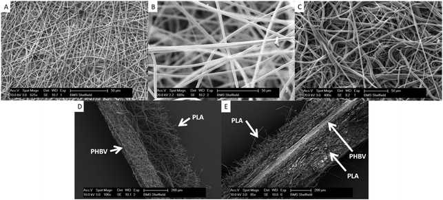 | ||
| Fig. 1 Scanning electron micrographs (SEMs) of electrospun scaffolds A. PHBV. B. PLA. C. PCL. D. Representative cross-section of PHBV–PLA. The PHBV region on the left is dense while the PLA region has a more open structure. E. Representative cross section of a trilayer of PLA–PHBV–PLA. | ||
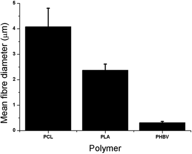 | ||
| Fig. 2 Mean fibre diameters for PCL, PLA and PHBV of 4 μm, 2.5 μm and 700 nm respectively. Values are taken from measurement of SEM images, presented as average + standard error of the mean (+SEM), n = 5. | ||
Table 1 shows porosity and mechanical data for the bulk polymer and electrospun scaffolds. Porosity measurements show a significant difference between the microfibrous scaffolds of PLA and PCL compared to the nanofibrous PHBV, with the microfibrous scaffolds being around 20% more porous. The Young's modulus (E) of the bulk polymer is higher than the measured E of the scaffolds in all cases. The highest E was recorded for the PLA–PHBV–PLA trilayer and is approximately 33% more than the next nearest, PHBV. Scaffolds containing PCL had E values of around 50% of those scaffolds not containing PCL.
| Scaffold | Bulk E/GPa | Scaffold E/GPa | Bulk density/g ml−1 | Scaffold density/g ml−1 | Porosity/% |
|---|---|---|---|---|---|
| PLA | 3.6 | 0.012 ± 0.001 | 1.25 | 0.18 | 85 ± 0.8 |
| PCL | 0.350 | 0.008 ± 0.003 | 1.145 | 0.25 | 78 ± 0.8 |
| PHBV | 0.5 | 0.015 ± 0.002 | 1.25 | 0.50 | 60 ± 1 |
| PHBV–PLA | N/A | 0.014 ± 0.008 | N/A | 0.24 | N/A |
| PHBV–PCL | N/A | 0.004 ± 6 × 10⁻⁵ | N/A | 0.30 | N/A |
| PLA–PHBV–PLA | N/A | 0.021 ± 0.001 | N/A | 0.21 | N/A |
Cell viability on scaffolds was demonstrated using a resazurin salt assay. Fig. 3 shows cell viability on the scaffolds after 7 days of culture compared to the same cells cultured on TCP. With respect to the attachment and expansion of fibroblasts all scaffolds compared reasonably well to TCP. Cells on PCL performed significantly worse than on TCP but only by approximately 30%, while cells on PHBV–PCL did significantly better (by approximately 20%). Scaffolds were less supportive of hESMP attachment and expansion with cell performance on all scaffolds being only approximately 50% as good as on TCP (Fig. 3B).
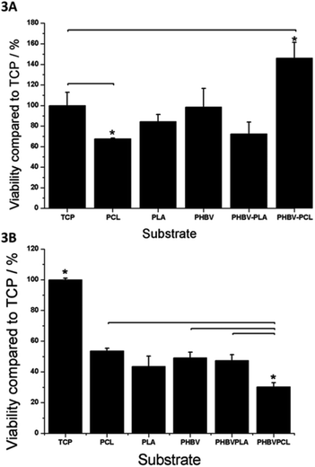 | ||
| Fig. 3 A. Cell viability (assessed by the resazurin salt assay) of fibroblasts on PCL, PLA, PHBV, PHBV–PLA and PHBV–PCL scaffolds after 7 days. All scaffolds supported cell viability to a similar extent to TCP cells except for PCL on which cell viability was significantly lower (by approximately 30%) and PHBV–PCL where cell viability was approximately 40% better than TCP. B. Cell viability (assessed by the resazurin salt assay) of hESMPs on PCL, PLA, PHBV, PHBV–PLA and PHBV–PCL scaffolds after 7 days. All scaffolds were significantly less effective (approximately 50% as effective) at supporting cell growth compared to TCP except for PHBV–PCL which was only 30% as effective as TCP (significantly lower than PCL, PHBV and PHBV–PLA). Values are mean + SEM, n = 3. | ||
Fig. 4 shows fluorescent images of the cells on TCP (Fig. 4A) and on scaffolds (Fig. 4B–F). When seeded together, there is clear mixing of the cells on TCP, PLA and PCL. On these PLA and PCL scaffolds it is evident that fibroblasts and hESMPs have migrated through the scaffolds, as each face of the scaffold shows both cell types. With PHBV, however, there is a clear segregation of cell types. Even after 7 days of culture of fibroblasts on one face of the PHBV and culture of hESMPs on the opposite face, the cells remain segregated as can be seen in Fig. 4D (for fibroblasts) and Fig. 4E (for hESMPs). Fig. 4F is a cross section of the PHBV with the cells on their respective surfaces. As there was no mixing of the red and green fluorescently labelled cells it appears that PHBV has been successful at both supporting cell attachment and keeping the two cell types segregated for at least 7 days.
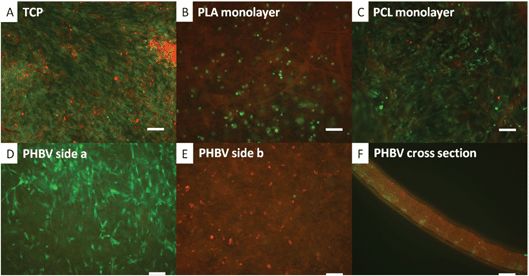 | ||
| Fig. 4 Co-culture of CellTracker™ labelled fibroblasts (green) and hESMPs (red) on a range of scaffolds. In A hESMPs were seeded on day 1 (red) followed by an equal ratio of fibroblasts on day 2 (green) and cultured for 7 days on TCP. In B–F hESMPs were seeded on one side of the scaffold on day 1, and then fibroblasts on the other side on day 2 and these were then cultured for a further 7 days. The scaffolds used were PLA in B, PCL in C and PHBV in D, E and F. In A, B and C there is a clear mixture of red and green cells. In D and E however cells remain segregated. All fibroblasts (green) are shown on the surface shown in D and all hESMPs (red) are seen on the opposite side (E). F shows a cross section of the PHBV scaffold with clear separation of the hESMPs and fibroblasts. Scale bars 0.1 mm. | ||
PHBV–PLA and PHBV–PCL bilayers were assessed for their ability to maintain cell segregation. Fig. 5A and D show the fibroblasts seeded on the PLA and PCL faces of the bilayers respectively. It is clear that hESMPs have not migrated through to this face. Likewise, Fig. 5B and E show the hESMPs seeded onto the PHBV faces of each bilayer respectively. Fig. 5C and F show cross sections through both bilayers with both the hESMPs and fibroblasts contained on their respective side.
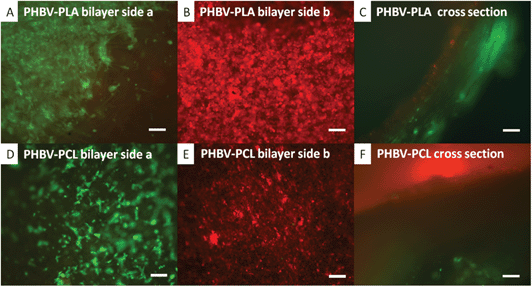 | ||
| Fig. 5 Co-culture of CellTracker™ labelled fibroblasts (green) and hESMPs (red) on bilayer membranes of either PHBV–PLA or PHBV–PCL. hESMPs were seeded on day 1 (red) onto the PHBV face of each bilayer. Fibroblasts were seeded on either the PLA or PCL face of the bilayer on day 2 (green) and then cultured for a further 7 days. In A fibroblasts (green) are confined to the PLA face after 7 days with no sign of hESMPs (red). On the opposite face (B, PHBV), hESMPs (red) are also present once again with no fibroblasts. A cross section of the PHBV–PLA membrane is shown in C showing each cell type on its respective side after 7 days of culture. In D and E, fibroblasts (green) and hESMPs (red) are shown on the PCL and PHBV faces respectively and there is no mixing across these faces. F shows a cross section of the PHBV–PCL membrane and clearly shows each cell type still confined to their respective faces after 7 days of culture. All scale bars are equal to 0.1 mm. | ||
The bone forming potential of hESMPs is demonstrated in Fig. 6. Continuous culture under appropriate conditions resulted in the cells differentiating into bone forming osteoblasts (increased alkaline phosphatase activity with time) and depositing calcium containing bone mineral (alizarin red staining).
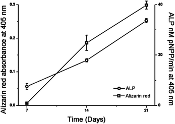 | ||
| Fig. 6 Alkaline phosphatase activity and quantification of alizarin red staining of hESMPs after 7, 14 and 21 days on TCP. Increasing alkaline phosphatase activity indicates cell differentiation towards osteoblastic (bone forming) cells and increasing alizarin red indicates increased calcium (present in bone mineral) deposition. Values are mean ± SEM, n = 3. | ||
The retained barrier properties of the PLA–PHBV–PLA trilayer scaffold are shown by the fluorescent images in Fig. 7. DAPI staining of the cell nuclei (blue) has been added to aid with visualising the cell nuclei. There are nuclei on either side of the scaffold, showing that both fibroblasts and keratinocytes adhere and proliferate. The face seeded with fibroblasts (green) shows no sign of keratinocytes (red) having penetrated through the scaffold. Likewise on the keratinocyte seeded face, there are no fibroblasts present. The final image shows a cross section, with both sides well populated by cells, but the fibroblasts and keratinocytes are confined to their respective sides. The recorded cell viability on the PLA–PHBV–PLA trilayer scaffold is good (around 50% compared to those on TCP). This is comparable to the bilayer scaffolds.
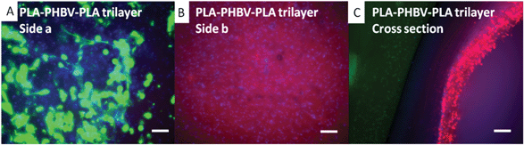 | ||
| Fig. 7 Co-culture of CellTracker™ labelled fibroblasts (green) and keratinocyte (red) on trilayer membranes of PLA–PHBV–PLA. Fibroblasts were seeded on day 1 (green) onto one face of each trilayer. Keratinocytes were seeded on the opposite face of the trilayer on day 4 (green) and then cultured for a further 7 days. In A, fibroblasts (green) are confined to the PLA face after 7 days with no sign of keratinocytes (red). On the opposite face, keratinocytes (red) are present once again without fibroblasts. A cross section of the PLA–PHBV–PLA membrane is shown in C showing each cell type on its respective side after 7 days of culture. Cell nuclei have been stained using DAPI (blue). All scale bars are equal to 0.1 mm. | ||
Decreasing the amount of the nanofibrous scaffold to 20% and 5% of the original weight does not appear to affect the barrier qualities of these trilayers with segregation of fibroblasts and keratinocytes maintained after 7 days also (Fig. 8).
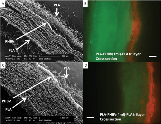 | ||
| Fig. 8 SEM and fluorescence microscopy of PLA–PHBV–PLA trilayers with reduced PHBV layer thickness. Panels A and C shows SEM cross sections of trilayers made using 1 ml and 4 ml of PHBV respectively (5% and 25% of original volume used in Fig. 4, 5 and 7. Microfibrous PLA is present on the top and bottom of each scaffold, with a dense nanofibrous PHBV slither through the middle of each. Panels B and D show fluorescence microscopy of cross sections with fibroblasts (green) cultured on one face and keratinocytes (red) cultured on the opposite face with separation maintained after a week (demonstrated by no ‘bleed though’ of the colours to opposite faces). | ||
Discussion
We demonstrate that a nanofibrous scaffold can act as a barrier to cell penetration while providing a scaffold for cell attachment and proliferation. For cleft palate treatment in the clinic, it would be our intention to culture autologous buccal mucosa on one face (as we have previously demonstrated) and autologous periosteal cells as a bone precursor on the opposite face.47 These are being investigated for their bone forming ability at present. These could be harvested at the time of a cleft lip repair, expanded in the laboratory, and then re-introduced on a bilayer membrane to encourage the growth of a native hard palate.The concept of segregating tissue for regenerative purposes is not new. It has been established in dentistry for some time where tissue guides have been developed to segregate soft tissue from bone forming tissue in periodontal repairs.18,19 Commercial materials include collagen-based membranes, biodegradable polymers and Teflon.2,51,52 Collagen has a high biodegradation rate, can be difficult to remove when there are problems, and can introduce the risk of infection as it is an animal derived tissue (usually bovine). Therefore, one must be mindful of the source of the collagen to avoid any risk of prion disease transmission.51 Teflon is a very successful and effective barrier to cells. However, it cannot be left implanted and follow up procedures are required to remove it. This is not ideal as it disturbs the newly repaired tissues risking scar formation and infection.53 Current biodegradable polymer solutions are commonly based on PLA, however, these are not entirely popular with surgeons as they are difficult to handle.54
In the current study the nanofibrous component of the bilayer and trilayer makes the material much more user-friendly, it can be readily picked up, shaped and handled without tangling, sticking or loss of shape, unlike microfibrous electrospun scaffolds.
The methodology of spinning one scaffold on top of another is reproducible and consistent. Our data show that by using cell tracker labelled cells it is possible to culture two different cell types on these scaffolds while maintaining segregation for at least 7 days.
The cell tracker fluorescent dyes are very successful at labelling cells through to 7 days, but the intensity of the dye decreases noticeably after longer periods.
In this study we simply examined fibroblast attachment as a soft tissue model. We selected hESMPs as a model bone forming cell as they are capable of forming bone (see Fig. 6), and are also an appropriate cell type against which other candidate cells can be compared.55,56 Here we present hESMP bone forming potential on TCP, and other studies have shown similar bone forming potential on other well known biodegradable polymers such as PCL, PLA and PLGA.57–60 Similarly we confirm that keratinocytes and fibroblasts are effectively segregated when cultured on a trilayer membrane separated by a nanofibrous scaffold layer.
Conclusions
In summary, we describe simple methods for electrospinning bilayer and trilayer nanofibrous/microfibrous membranes capable of supporting the culture of two very different cell types, while maintaining segregation between the two. We hope that these will prove useful in a range of applications such as the first step in developing an approach for tissue engineering of cleft palate and also guided tissue regeneration for periodontal disease and in production of tissue engineered skin for treatment of patients with extensive full thickness burns injuries.Acknowledgements
We thank the BBSRC for funding a PhD for Frazer Bye and the Narusuan University for funding a PhD for Sasima Puwanun.Notes and references
- J. Middleton and A. Tipton, Biomaterials, 2000, 21, 2335–2346 CrossRef CAS.
- M. Sabir, X. Xu and L. Li, J. Mater. Sci., 2009, 44, 5713–5724 CrossRef CAS.
- J. Jang, O. Castano and H. Kim, Adv. Drug Delivery Rev., 2009, 61, 1065–1083 CrossRef CAS.
- L. Griffith and A. Grodzinsky, Oppor. Med. Res., 2001, 285, 556–561 CAS.
- Y. Ikada, Interface, 2006, 3, 589–601 CAS.
- P. Warnke, I. Springer, Y. Acil, H. Bolte, P. Russo, E. Sherry, H. Terheyden, J. Wiltfang, H. Eufinger, E. Behrens and M. Wehmoller, Lancet, 2004, 364, 766–770 CrossRef CAS.
- P. Warnke, J. Wiltfang, I. Springer, Y. Acil, H. Bolte, M. Kosmahl, P. Russo, E. Sherry, U. Lutzen, S. Wolfart and H. Terheyden, Biomaterials, 2006, 27, 3163–3167 CrossRef CAS.
- S. Terada, M. Sato, A. Sevy and J. Vacanti, Yonsei Med. J., 2000, 41, 685–691 CAS.
- K. Rustad, M. Sorkin, B. Levi, M. Longaker and G. Gurtner, Organogenesis, 2010, 6, 151–157 CrossRef.
- J. Larrick and A. Mendelsohn, Rejuvenation Res., 2010, 13, 265–280 CrossRef.
- P. H. Warnke, Lancet, 2006, 368, 181–183 CrossRef.
- W. Rowiński, Ann. Transplant., 2007, 12, 5–10 Search PubMed.
- S. Bhargava, C. Chappel, A. Bullock, C. Layton and S. MacNeil, Br. J. Urol., 2004, 93, 807–811 CAS.
- S. Bhargava, J. Patterson, R. Inman, S. MacNeil and C. Chapple, Eur. Urol., 2008, 53, 1263–1271 CrossRef.
- G. C. Reilly and A. J. Engler, J. Biomech., 2010, 43, 55–62 CrossRef.
- L. Freed, G. Engelmayr, J. Borenstein, F. Moutos and F. Guilak, Adv. Mater., 2009, 21, 3410–3418 CrossRef CAS.
- A. Yen and P. Yelick, Gerontology, 2010, 57, 85–94 CrossRef.
- J. Moreau, J. Caccamese, D. Coletti, J. Sauk and J. Fisher, J. Oral Maxillofac. Surg., 2007, 65, 2503–2511 CrossRef.
- M. Retzepi and N. Donos, Clin. Oral Implants Res., 2010, 21, 567–576 CrossRef.
- P. Mossey, Addressing the global challenges of craniofacial anomalies. Report of a WHO meeting on international collaborative research on craniofacial anomalies, World health organisation technical report, 2004.
- B. Sommerland, J. R. Soc. Med., 1989, 82, 677–679 Search PubMed.
- J. Lilja, Scand. J. Surg., 2003, 92, 269–273 CAS.
- G. Nellhaus, Paediatrics, 1968, 41, 106–114 CAS.
- R. Langford, S. Sgouros, K. Natarajan, H. Nishikawa, M. Dover and A. Hockley, Plast. Reconstr. Surg., 2003, 111, 1591–1597 CrossRef.
- J. G. Rheinwald and H. Green, Cell, 1975, 6, 331–343 CrossRef CAS.
- A. J. Bullock, M. C. Higham and S. MacNeil, Tissue Eng., 2006, 12, 245–255 CrossRef CAS.
- T. Sun, M. Higham, C. Layton, J. Haycock, R. Short and S. MacNeil, Wound Repair Regen., 2004, 12, 626–634 CrossRef.
- WD. Luzier, Proc. Natl. Acad. Sci. U. S. A., 1992, 89, 839–842 CrossRef CAS.
- M. Yasin, S. Hollands and B. Tighe, Biomaterials, 1990, 11, 451–455 CrossRef CAS.
- S. Holland, A. Jolly, M. Yasin and B. Tighe, Biomaterials, 1987, 8, 289–295 CrossRef CAS.
- H. Li, W. Zhai and J. Chang, J. Mater. Sci. Mater. Med., 2008, 19, 67–73 CrossRef CAS.
- D'Agnostino and William, US Pat.20090112259, 2009 Search PubMed.
- E. Shishatskaya, T. Volova and I. Gitelson, Dokl. Biol. Sci., 2001, 383, 109–111 CrossRef.
- M. Wang, Biomaterials, 2003, 24, 2133–2151 CrossRef CAS.
- F. Yang, R. Maurugan, S. Wang and S. Ramakrishna, Biomaterials, 2005, 26, 2603–2610 CrossRef CAS.
- T. Telemeco, C. Ayres, G. Bowlin, G. Wnek, E. Boland, N. Cohen, C. Baumgarten, J. Mathews and D. Simpson, Acta Biomater., 2005, 1, 377–385 CrossRef CAS.
- L. Suggs and S. Moore, in Physical Properties of Polymers Handbook, ed. J.E. Mark, Springer, 2nd edn, 2007, ch. 55, pp. 939–950 Search PubMed.
- E. Engelhardt, L. Micol, S. Houis, F. Wurm, J. Hilborn, J. Hubbell and P. Frey, Biomaterials, 2011, 32, 3969–3976 CrossRef CAS.
- I. Canton, R. McKean, M. Charnley, K. Blackwood, C. Fiorica, A. Ryan and S. MacNeil, Biotechnol. Bioeng., 2010, 105, 396–408 CrossRef CAS.
- K. Blackwood, R. McKean, I. Canton, C. Freeman, K. Franklin, A. Cole, I. Brook, P. Farthing, S. Rimmer, J. Haycock, A. Ryan and S. MacNeil, Biomaterials, 2008, 29, 3091–3104 CrossRef CAS.
- J.-T. Schantz, S. H. Teoh, T. C. Lim, M. Endres, C. X. F. Lam and D. W. Hutmacher, Tissue Eng., 2003, 9(Suppl 1), S113–S126 CrossRef CAS.
- M. A. Woodruff and D. W. Hutmacher, Prog. Polym. Sci., 2010, 35, 1217–1256 CrossRef CAS.
- V. Guarino, F. Causa, P. Taddei, M. di Foggia, G. Ciapetti, D. Martini, C. Fagnano, N. Baldini and L. Ambrosio, Biomaterials, 2008, 29, 3662–3670 CrossRef CAS.
- S. A. Abbah, C. X. L. Lam, D. W. Hutmacher, J. C. H. Goh and H.-K. Wong, Biomaterials, 2009, 30, 5086–5093 CrossRef CAS.
- J.-T. Schantz, T.-C. Lim, C. Ning, S. H. Teoh, K. C. Tan, S. C. Wang and D. W. Hutmacher, Neurosurgery, 2006, 58, ONS-E176 CrossRef.
- S. MacNeil, Nature, 2007, 445, 874–880 CrossRef CAS.
- M. Selim, A. J. Bullock, K. A. Blackwood, C. R. Chapple and S. MacNeil, Br. J. Urol. Int., 2010, 107, 296–302 CrossRef.
- F. Bye, L. Wang, A. Bullock, K. Blackwood, A. Ryan and S. MacNeil, J. Vis. Exp., 2012, e4172 Search PubMed.
- F. Dullien, Porous Media Fluid Transport and Pore Structure, Academic Press, 1979 Search PubMed.
- S. Eshraghi and S. Das, Acta Biomater., 2010, 6, 2467–2476 CrossRef CAS.
- M. Bornstein, D. Bosshardt, D. Buser, S. Chen, S. Jensen, I. Rocchietta, R. Schenk, M. Simion and T. von Arx, 20 Years of Guided Bone Regeneration in Implant Dentistry, Quintessence Publishing Co, Inc, 1994, pp. 86–139 Search PubMed.
- D. Lundgren and C. Slotte, J. Clin. Periodontol., 1999, 26, 56–62 CAS.
- S. Ivanovski, Aust. Dental J., 2009, 54, S118–S128 CrossRef.
- A. Cipitria, A. Skelton, T. R. Dargaville, P. D. Dalton and D. W. Hutmacher, J. Mater. Chem., 2011, 21, 9419–9453 RSC.
- G. M. de Peppo, P. Sjovall, M. Lenneras, R. Strehl, J. Hyllner, P. Thomsen and C. Karlsson, Tissue Eng. Part A, 2010, 16, 3413–3426 CrossRef CAS.
- C. Karlsson, K. Emanuelsson, F. Wessberg, K. Kajic, M. Z. Axell, P. S. Eriksson, A. Lindahl, J. Hyllner and R. Strehl, Stem Cell Res., 2009, 39–50 CrossRef.
- X. Xin, M. Hussain and J. J. Mao, Biomaterials, 2007, 28, 316–325 CrossRef CAS.
- J. Hu, L. A. Smith, K. Feng, X. Liu, H. Sun and P. X. Ma, Tissue Eng. Part A, 2010, 16, 3507–3514 CrossRef CAS.
- J. Nam, J. Johnson, J. J. Lannutti and S. Agarwal, Acta Biomater., 2011, 7, 1516–1524 CrossRef CAS.
- R. M. Delaine-Smith, S. MacNeil and G. C. Reilly, Eur. Cell Mater., 2012, 24, 162–174 CAS.
| This journal is © The Royal Society of Chemistry 2013 |