Polyaniline/polyacrylic acid/multi-walled carbon nanotube modified electrodes for sensing ascorbic acid†
Ida
Tiwari
*a,
Karan Pratap
Singh
a,
Manorama
Singh
a and
Craig E.
Banks
*b
aDepartment of Chemistry (Centre of Advanced Study), Faculty of Science, Banaras Hindu University, Varanasi, INDIA. E-mail: idatiwari_2001@rediffmail.com; Fax: +91-542-2368174; Tel: +91-9415813020
bFaculty of Science and Engineering, School of Science and the Environment, Division of Chemistry and Environmental Science, Manchester Metropolitan University, Chester Street, Manchester, M1 5GD, Lancs, UK. E-mail: c.banks@mmu.ac.uk; Fax: +44 (0) 1612476831; Tel: + 44 (0) 1612471196
First published on 1st December 2011
Abstract
A multi-walled carbon nanotube composite electrode incorporating Polyaniline (PANI) and Polyacrylic acid (PAA) is presented by diffusing aniline and PAA into Nafion- MWCNTs membranes supported upon a platinum macrodisc electrode. Nafion is found to be an ideal medium for dispersion of MWCNTs and for the formation of a homogeneous composite. The composite has been characterized utilizing SEM, TEM, FT-IR and electrochemical techniques. Electrochemical characterization reveals that the redox activity of the composite is improved with the cumulative effect of MWCNTs and PAA as additives. The electroanalytical behavior of the composite is evaluated towards the sensing of ascorbic acid in the presence of dopamine and uric acid exhibiting a detection limit of 2.5 × 10⁻⁷ M.
Introduction
Sensor technologies have been developing rapidly over the last few decades and rapidly new classes of materials and hybrid systems have evolved for achieving improved properties. Carbon nanotubes (CNTs) have demonstrated a wealth of exceptional structural, mechanical, chemical and electronic properties due to high aspect ratios, chemical stability and high young's modulus which have made them potentially useful for applications in nanotube reinforced materials, nanoelectronic devices, field emitters and probe tips for SPMetc.1–5 In addition, CNTs act as efficient conduits for electrons and it improves the conductivity of the composite material due to its high conductivity.6 The formation of MWCNT/polymer composite is considered as a promising approach for various applications such as charge storage systems, electrochromic devices, electronics, electrochemical actuators, sensors and separation devices, antistatic coating, anticorrosive coating, secondary batteries and fuel cells.7,8 To date several methods have been developed to prepare the polymer/nanotube composites efficiently, including dissolving the polymer in an organic solvent containing multi-walled carbon nanotubes, melt mixing, in situpolymerization, grafting macromolecules to the CNTs and electrochemistry.5However, the developments of such composites have been impeded by the inability to disperse CNTs into polymer matrixes due to lack of chemical compatibility between the chosen polymers and CNTs.9 This is in part because of the difficulties in material processing arising from insolubility of pristine CNTs in most solvents. To overcome these limitations, different strategies have been adopted such as dispersion into different solvents, the use of polyelectrolytes, functionalization and incorporation in composite matrixes using distinct binders.10Nafion a copolymer of tetrafluoroethylene and perfluoro-3, 6-dioxa-4-methyl-7-octene-sulfonic acid has been recently reported as a medium for dispersion of CNTs.11
Though several studies have been conducted on PANI/CNTs composites,12 the electron conduction and stability of the composites still remains an issue which is due to another challenge since PANI remains electro-active only in acidic conditions, normally pH < 5,13 a feature that limits its broad use, especially the application as a sensing platform requiring a neutral or alkaline environment. Consequently in recent years incorporation of ionogenic groups to the PANI structure has been performed which hinder the deprotonation of the conducting form of PANI and thus extend its electro-activity towards less acidic pHs. Polyacrylic acid “(CH2CHCOOH)x” (PAA) is one of the common bulky polymeric dopant used for doping of conducting polymers.14 Polymeric acid doped PANI displays better stability and electro-activity at higher pH with improved mechanical properties.15 Moreover, the incorporated dopants are not easily released from the polymer matrixes due to its huge molecular size and electrostatic interaction with the positive charge of conducting polymer backbone.16 In terms of applications, it has also been observed that catalytic currents of hydrogen at PANI/PAA/Pt are much higher than those of the PANI/Pt electrode17 suggesting many analytical applications of these composites.
Consequently in this paper we report a facile methodology to fabricate PANI/PAA/MWCNTs composite electrodes supported upon a platinum macrodisc electrode. The composite is well characterised using SEM, TEM, FTIR and voltammetry.
Ascorbic acid is the most commonly used anti oxidant and its determination is often considered important as it is required nutrient for humans and its importance in collagen synthesis, hormone synthesis.18 Various methods are available for its estimation such as titrimetry, fluorimetry, flow-injection analysis, spectrophotometry, chromatography, and atomic absorption spectrophotometry, electrochemical.19–21 There is a need for the modification of electrode surface for electrochemical determination of ascorbic acid because it is electro-active and it is difficult to determine this compound electrochemically by direct oxidation on a conventional electrode due to fouling of the electrode surface from the oxidation product.22 Additionally conventional electrodes (unmodified Pt or gold or glassy carbon) show large over potential which is much higher than its thermodynamics redox potential, 1.0 V.23 Besides this, ascorbic acid coexists with dopamine and uric acid in body fluids and their oxidation potentials are very close. Hence, selective determination of ascorbic acid in the presence of dopamine and uric acid is a challenge. Mediating materials can mediate the oxidation of ascorbic acid in acidic solution and reduces the overpotential of ascorbic acid hence they facilitate selective determination of ascorbic acid even in presence of dopamine and uric acid.24,25 Among the approaches available26,27polymer modified electrodes are widely used because they can provide more active sites than that fabricated through covalent binding or adsorption.28 Consequently we explore our composite electrode towards the electroanalytical sensing of ascorbic acid in aqueous solution in the presence of dopamine and uric acid and benchmark this against other literature reports29–34 utilizing electrochemical methods for the sensing of these analytes.
Experimental
Materials and reagents
Aniline monomer was obtained from Qualigens, India and distilled under reduced pressure and stored below 4 °C. Polyacrylic acid (Aldrich, MW 2100), MWCNTs (Aldrich, purity 90%), before use it was purified by heating in HCl (5 M) followed by ultrasonication for 30 mins and rinsed with triple distilled water and Nafion (5% commercial solution, Aldrich US) [20 μL of Nafion solution was diluted with 80 μL of distilled water (1![[thin space (1/6-em)]](https://www.rsc.org/images/entities/char_2009.gif) :
:![[thin space (1/6-em)]](https://www.rsc.org/images/entities/char_2009.gif) 4)], Ascorbic acid, dopamine and uric acid were obtained from Aldrich, MA, USA. 1 M sulfuric acid, 0.1 M phosphate buffer (pH 5.5 and 6.6) solutions were made using analytical grade reagents and triple distilled water.
4)], Ascorbic acid, dopamine and uric acid were obtained from Aldrich, MA, USA. 1 M sulfuric acid, 0.1 M phosphate buffer (pH 5.5 and 6.6) solutions were made using analytical grade reagents and triple distilled water.
Apparatus
Electrochemical experiments were carried out with an electrochemical analyzer CH-630C series, CH instruments, USA. A platinum macrodisc electrode, 2 mm in diameter was used as working electrode. The auxiliary and the reference electrodes were a platinum wire and an Ag/AgCl electrode respectively. Scanning Electron Microscope (SEM) and Tunneling Electron Microscope (TEM) images were obtained using JEOL 840A Japan, Tecnai G2 electron microscope respectively. Polymerized films over Pt disc electrode were dried for SEM and scratched out for TEM. Scratched material was dispersed in distilled water and it was coated over copper grid for TEM analysis. Fourier Transform infrared (FTIR) spectra in KBr pellets were obtained in the range of 500–4000 cm−1 using Schimadzu Spectrophotometer, Japan at room temperature.Procedure
![[thin space (1/6-em)]](https://www.rsc.org/images/entities/char_2009.gif) :
:![[thin space (1/6-em)]](https://www.rsc.org/images/entities/char_2009.gif) 4 ratio of Nafion and triple distilled water) and dispersed by ultrasonication. A well dispersed Nafion- MWCNTs solution was obtained by ultrasonication for 6 h at room temperature. 10 μL of this solution was dropped on the platinum disc electrode and kept for one hour to dry. The thickness of the nafion film is estimated to be ∼ 0.54 μm using a density of 1.58 gcm−3.
4 ratio of Nafion and triple distilled water) and dispersed by ultrasonication. A well dispersed Nafion- MWCNTs solution was obtained by ultrasonication for 6 h at room temperature. 10 μL of this solution was dropped on the platinum disc electrode and kept for one hour to dry. The thickness of the nafion film is estimated to be ∼ 0.54 μm using a density of 1.58 gcm−3.
Results and discussion
Electropolymerisation
On comparing the electropolymerisation data of different systems (Fig. 1) it can be clearly observed that the magnitude of current increases with the effect of Nafion [Fig. 1 (b)] and Nafion/MWCNTs [Fig. 1 (c)] as compared to PANI-PAA at a bare platinum macroelectrode surface [Fig.1(a)]. Three sets of redox couples were obtained when PANI alone was polymerised on the platinum macroelectrode in acidic solution.35On polymerisation of PANI with PAA (System 1) only a single redox couple with peak potentials of + 0.494 V and + 0.312 V (vs.Ag/AgCl) [cf.Fig.1 (a)] is observed which may be due to adsorption of aniline monomers through electrostatic and/or hydrogen bonding interaction onto PAA to afford the interpolymer PANI-PAA complex.36 The polymerisation rate falls by 3 in comparision to PANI in absence of PAA (results not shown) which indicates large polyanions have been incorporated into PANI matrix and then impedes the effective doping of small molecular anions in the electrolyte as previously reported.37Nafion modified electrode (System 2) shows two redox couples with formal potentials of + 0.084 V (leucoemeraldine and emeraldine couples), + 0.58 V (emeraldine and pernigralline couples) with higher peak currents as compared to System 1; this suggests an improved electro-activity of PANI/PAA over Nafion matrixes. Furthermore when PANI/PAA was electrochemically synthesised from an acidic media (H2SO4) at a Nafion-MWCNTs modified platinum macroelectrode (System 3) by sweeping the potential from −0.2 to 0.8 V (vs.Ag/AgCl) at a scan rate of 0.1 V s−1, the composite exhibited two pairs of redox peaks with formal potentials of +0.065 V and + 0.604 V. Initially, the electrochemical oxidation of aniline occurred at approximately +0.8 V, resulting in the nucleation of PANI.38 An increase in the amplitude of the redox peaks was observed as a consequence of repeated potential scans, indicative of polymer deposition at the electrode and the formation of a conducting polymer. The addition of MWCNTs increases the current further and lowers the peak separation. It may be inferred that the MWCNTs shifted the protonation and deprotonation reaction in a more reversible manner and the movements of anions were hindered in this matrix.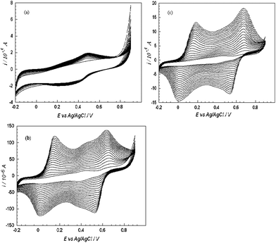 | ||
| Fig. 1 Electropolymerisation of aniline in the presence of PAA in 1 M H2SO4 on: (a) bare, (b) Nafion modified and (c) Nafion-MWCNTs modified platinum macrodisc electrode. Scan rate: 100 mV s−1. | ||
Morphological studies (SEM and TEM)
The morphology of the composite materials was investigated by SEM and TEM. SEM mages of PANI are shown in Fig. 2 displays a loose and granulated structure as previously reported.37PANI-PAA film [cf.Fig. 2 (a)] shows a sponge like structure with less void space, composed of an entangled and compact polymer chains. The SEM micrograph of PAN/PAA/MWCNTs [cf.Fig. 2 (b)] in the absence of nafion shows entangled and closely packed long polymer chains with some irregularities in the form of some aggregates which may be due to non-dispersion of MWCNTs. The SEM images of Nafion-MWCNTs membrane [cf.Fig. 2 (c)] show an uniform distribution of MWCNTs in Nafion matrix. Further, Fig. 2 (d) shows SEM images of PANI-PAA/MWCNTs modified electrode when PANI along with PAA deposited over the Nafion-MWCNTs membrane coated Pt electrode. The SEM images show a homogeneous coating which indicates uniform deposition of additives in the composite with the induction of crystallinity. It can also be observed that the composite film displays a new interwoven fibrous network. The surface appears more compact which indicates an increase in the surface area of the composite which may be responsible for increased currents observed as discussed in preceding section.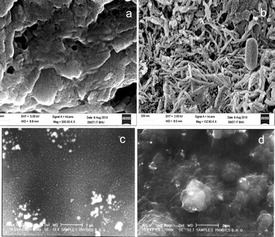 | ||
| Fig. 2 SEM images of (a) PANI-PAA, (b) PANI-PAA-MWCNTs composite without dissolving MWCNTs in Nafion, (c) Nafion/MWCNTs membrane and (d) PANI/PAA/MWCNTs modified electrode. | ||
Fig. 3 (a) shows the TEM images of Nafion and MWCNTs. Nafion has hydrophobic and hydrophilic regions and can wrap around hydrophobic MWCNTs surface and hence completely separate them.39 The inset to Fig. 3(a) shows the electron diffraction pattern of Nafion-MWCNTs membrane which does not indicate crystalline nature. The inside structure of the composite material revealed the presence of nano structures of size 30–40 nm as supported by TEM images [cf.Fig. 3 (b)]. The Nafion-MWCNTs membrane forced the self organization of PANI/PAA during electropolymerization with MWCNTs acting as fillers, which resulted in crystalline nature of the composite as is indicated by the electron diffraction pattern [inset to Fig. 3 (b)].
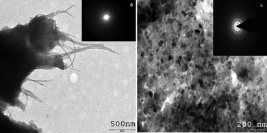 | ||
| Fig. 3 (a) TEM photograph of Nafion/MWCNTs membrane, Inset: Diffraction pattern of Nafion/MWCNTs membrane and (b) TEM images of PANI/PAA/MWCNTs modified electrode. Inset: Diffraction pattern. | ||
In this composite, crystallites may be supposed as metallic granules and electronic transport may occur by hopping between conducting grains which is responsible for increase in currents as discussed vide infra. The morphology of PANI, PAA and MWCNTs together was quite different as compared to morphology of individual and binary systems i.e.PANI-NAFION, PANI-MWCNTs, PANI-PAA,17, 40– 42 which may be due to cumulative effect of PANI/PAA with MWCNTs as fillers.
The crystals obtained are the new finding of our work as such crystalline structures are being reported for the first time at normal conditions. Quite trivial conditions are reported earlier to prepare semiconducting nanocrystalline polymeric thin film by vacuum deposition method.43
FTIR
To completely investigate the nature of the composite material FTIR study was conducted for various sets (cf. supplementary material 1) listed: (a) set 1: Pure chemically polymerized aniline in 1 M sulfuric acid; (b) Set 2: Pure electrochemically polymerized aniline in 1 M sulfuric acid; (c) Set 3: Aniline polymerized with PAA over Pt disk electrode in 1 M sulfuric acid (System 1); (d) Set 4: Aniline polymerized with PAA over Nafion modified electrode in 1 M sulfuric acid (System 2); (e) Set 5: Aniline polymerized with PAA over MWCNTs modified electrode in 1 M sulfuric acid; (f) Set 6: Aniline polymerized over Nafion- MWCNTs modified electrode in 1 M sulfuric acid and (g) Set 7: Aniline polymerized with PAA over Nafion-MWCNTs modified electrode in 1 M sulfuric acid (System 3) depicted in Fig. 4.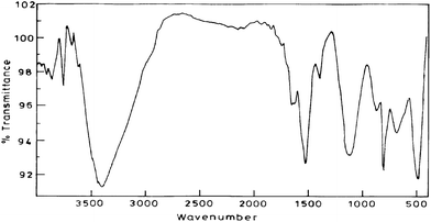 | ||
| Fig. 4 FTIR of the composite material which is aniline polymerised with PAA over Nafion-MWCNTs modified electrode in 1 M sulfuric acid (System 3). | ||
The absorption at around 3400, 1400–1600 cm−1 which are common for all sets are characteristic of the various vibration modes of the C–H and C–C bonds of the aromatic nuclei.44 The broad band near 3460 cm−1 corresponds to stretching of the N–H bonds. The band at 1300 cm−1 is assigned to the stretching of the C–N bonds of the aromatic amines. The strong band around 1140 cm−1 is considered to be a measure of the degree of delocalization and thus is characteristic peak of PANI conductivity.45,46 The presence of PAA in sets 3,4,5,7 is confirmed by the presence of peaks at around 2916 and 2854 cm−1 which can be attributed to C–H stretching vibrations of acrylic acid and presence of band around 1650 cm−1 in all the four cases attributed to asymmetric stretching of the carboxylate group. A strong and broadened band near 1100–1155 cm−1 due to B–N+ = Q (B is benzenoid and Q quinoid structures) which is a measure of the degree of delocalization of Π-electrons in PANI chain, the maximum shifting was observed for system 3 i.e. Set-7 [cf.Fig. 4] as compared to spectra for Set 1 at 1125.9 cm−1, for Set 2 at 1024.9 cm−1, for Set 3 at 1162.7 cm−1, for Set 4 at 1114.4 cm−1, for Set 5 at 1113.4 cm−1, for Set 6 at 1097 cm−1 which indicates that in our composite there is a facilitated charge transfer from a localized to delocalized band structures. The intensity of peak at around 1120 cm−1 is also increased maximum in Set-7 [cf.Fig. 4] which again indicates maximum degree of delocalization and points to higher conductivity than other sets which is corroborated with impedance measurements as discussed vide infra. On comparing the FTIR spectra of the prepared composite with PANI composites reported earlier47,48 on similar grounds again there is an indication of facilitated charge transfer. Peaks at positions 449 cm−1, 478 cm−1, 665 cm−1, 857 cm−1 in the system 3 i.e. Set-7 were having higher intensity as compared to other sets indicating free vibration of C–H and N–H bonds suggesting that the density of the composite was less than that of pure PANI.45
The peak at 3460 cm−1is increased in the presence of MWCNTs in system 3 which may be due to interaction of PANI with MWCNTs whereby sp2 carbons of MWCNTs compete with dopant ions and perturb the H-bond resulting in an increase in the N–H stretching intensity.49 Another difference can be observed in the intensity ratio of the benzenoid and quinoid bands. Relative intensity of band at 1570 cm−1 (C–N stretching of quinoid form) is higher than band at 1492 cm−1(C–N stretching of benzenoid rings) in set-7 which reveals quinoid form dominated than benzenoid form, as compared to other sets. These results suggest that presence of MWCNTs stabilizes the quinoid ring structure and the Π- bonded surface of the MWCNTs might interact strongly with the conjugated structure of PANI especially through the quinoid ring.
Electrochemical characterization of PANI/PAA/MWCNTs modified electrode
The cyclic voltammograms of the composite was recorded in the presence of PBS, pH 5.0 (0.1 M) at a scan rate of 100 mV s−1, which is shown in Fig.5. It is well known that the shape of cyclic voltammograms of PANI modified electrodes depends on three main factors; the pH of the supporting electrolyte, the anions associated with the dopants that neutralize the positive charge produced by oxidation of the conducting polymer, and the morphology of film. The conductivity and redox behavior of PANI is pH dependent and it loses its electro-activity easily at pH values above 4.0.50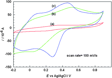 | ||
| Fig. 5 Cyclic voltammograms of PANI (a) with PAA, (b) with Nafion/PAA and (c) with PAA on Nafion-MWCNTs membranes. | ||
When PANI alone was polymerized in presence of MWCNTs the cyclic voltammogram (result not shown) displayed a couple of strong and broad oxidation and reduction waves with a large peak separation of + 0.3 V as already reported.38Fig. 5 curve (a) depicts a cyclic voltammogram of PANI/PAA composite (System1) deposited at a platinum disc macroelectrode which displays one redox peak at + 0.353 V and + 0.222 V (vs.Ag/AgCl). This redox peak is attributed to the conversion of emaraldine form to nigraline form and vice versa.51 The anodic and cathodic current of PANI/PAA composite was observed to be 10 μA and −11.5 μA respectively. In the presence of Nafion membrane (System 2) [cf.Fig. 5 curve (b)] the anodic peak shifts towards more positive potential from + 0.353 V to + 0.511 V (vs.Ag/AgCl) and cathodic peak shifts towards more negative value from + 0.220 V to + 0.062 V (vs.Ag/AgCl) with a large peak separation of about + 0.449 V (vs.Ag/AgCl) observed as compared to + 0.131 V (vs.Ag/AgCl) without Nafion (system 1). There is a significant increment in the current, up to −90 μA. This increment in the magnitude of the current response shows a direct correlation with the conductivity of the material and the effect of additives on the redox activity of PANI.
The cyclic voltammogram of PANI-PAA in presence of only MWCNTs could not be obtained as material could not be retained on the electrode for a long period of time and is completely washed out in PBS. Fig. 5 curve (c) shows cyclic voltammogram when MWCNTs were incorporated in the Nafion membrane (System 3). It is observed that there was further enhancement in the current for both cathodic and anodic peaks −111.8 μA and 94.1 μA at 0.457 V and 0.275 V vs.Ag/AgCl respectively and peak separation also decreased from 0.449 V to 0.182 V vs.Ag/AgCl. It may be concluded that the system 3 is more efficient as compared to other systems viz.1 and 2 or other reported composites. It can be clearly observed that the shape of the redox couple improved with the effect of MWCNTs. MWCNTs- Nafion layer covered on the top of platinum electrode also serves some other important purposes. Nafion effectively separates MWCNTs and prevents the leakage of MWCNTs. Probably the high conductivity, catalytic effect and homogeneous distribution of MWCNTs in Nafion caused the formation of better quality of PANI composites. It may be inferred that MWCNTs- Nafion matrix provided catalytic centers for the growth of PANI/PAA where MWCNTs present as fillers facilitated the charge delocalization at the PANI backbone and promoted the protonation of PANI. Negatively charged nafion membrane has been previously used to eliminate the effect of ascorbic acid.52,53 It was observed in the present case that the performance of the sensor depended greatly on the thickness of the coated Nafion membrane. Experimental results showed that coating of 10 μl of diluted nafion solution was optimal for achieving high sensitivity and stability of sensor.
A plot of anodic and cathodic peak currents vs. scan rate for system 3 yielded a straight line as expected for a surface process. The surface coverage concentration (Γ) of composite (system 3) was evaluated from the following equation. Γ = Q/nFA where A (0.031 cm2) is the area of the working electrode, n the number of electron per reactant molecule, Q (1.49 × 10 −4 C) the charge obtained by integrating the anodic peak at low voltage scan rate (5 mVs−1), and F is the Faraday Constant. In the present case, the calculated value of Γ is 4.91 × 10 −8 mol cm−2. The stability of composite modified platinum electrode was investigated by cyclic voltammetry. The peak height and peak potential of the surface-immobilized film created by cycling the electrode potential over the range −0.2 to 0.8 V remained nearly unchanged and the amount of degradation after 150 cycles (not shown) in electrolyte solution with scan rate 100 mV s−1 was less than 2%. Also the stability of the modified electrode and the reproducibility of its electrochemical behavior were investigated by cyclic voltammetry. The modified electrode was kept under ambient conditions for a long period of time (>5 months), and the cyclic voltammograms recorded after this period showed no recognizable change as compared to the original cyclic voltammogram. The high stability of the modified electrode is related to the mechanical and chemical stability of composite. This modified electrode can be potentially used as an electro-catalytic layer in electrochemical sensor devices, as discussed vide infra.
Impedance analysis
Electrochemical impedance spectroscopy (EIS) of PANI/PAA and PANI/PAA/MWCNTs were carried out at open circuit potential (OCP) in a three electrodes cell assembly using polymer/composite coated Pt disc electrode as working electrode in 0.1 M PBS (pH 5.0) in the frequency range 0.01 Hz to 1 × 10⁴ Hz. Fig. 6 shows Nyquist plot, where imaginary impedance component (Z′′) against the real impedance component (Z′) at each excitation frequency are shown. Both spectraFig. 6(A) and Fig 6(B) display nearly similar characteristics. Mixed kinetic and charge transfer control reaction was observed. A depressed semi-circle in the high frequency region and a straight line in the low frequency region were observed for both the system, which was reported for polymeric film-coated metals in the asymmetric metal/polymeric film/electrolyte configuration.54 Inset of Fig. 6 shows the proposed equivalent circuit which has been used for the fitting of impedance data of PANI/PAA copolymer and composite. Equivalent circuit R(Q(R(QR)(Q(RW)))) was used to get parameters. The important simulated parameters derived from copolymer and composite samples are shown in Table 1.| Systems | Rs (Ω) | Capacitance (F) | Rct (Ω) | Y0 |
|---|---|---|---|---|
| a Rs = Solution resistance. RCT = Charge transfer resistance. Y0 = Warburg constant due to diffusion of species. | ||||
| PANI/PAA | 253 | 1.33 × 10⁻⁵ | 440 | 6.338 |
| PANI/PAA/MWCNTs | 302 | 1.52 × 10⁻⁵ | 235 | 2.087 × 10⁻² |
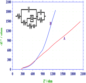 | ||
| Fig. 6 Nyquist plot of (a) PANI-PAA and (b) PANI/PAA/MWCNTs modified electrodei.e. system 3 in PBS, pH 5.0 (0.1 M) in frequency range 0.01 to 10000 Hz. Inset equivalent-circuit model for the PANI/PAA/MWCNTs modified electrode. | ||
On comparison of the impedance spectra it is found that the diameter of the semi-circle decreases in PANI/PAA/MWCNTs composite [cf.Fig. 6(A)]. The charge transfer resistance (Rct) reduced from 440 (PANI/PAA film) to 235 (PANI/PAA/MWCNTs) for composite film. This faster charge transfer can be explained in the terms of presence of continuous network for charge hopping because in the presence of CNTs as filler, charge trapping centres in copolymer matrix are reduced and a continuous conducting channel was provided for the charge participations.55
Electroanalytical application of the composite material
The oxidation potential of ascorbic acid depends on the electrode material;56 the potential at a bare glassy carbon and platinum electrode is + 0.4 V and + 0.6 V (vs.SCE) as already reported.57 In our case oxidation at bare platinum disk electrode occurred at + 0.702 V (vs.Ag/AgCl). The anodic current at composite modified electrode is 8.6 × 10⁻⁵ A at +0.30 V (cf.Fig.7). The increment of anodic current with the increased concentration of ascorbic acid at lower potential than bare electrode surface is a hard evidence of catalytic behavior of our composite material. Other than that composite prevented the fouling of the electrode as a result the electrode shows reproducible response. Amperometric response have been observed in the presence of dopamine and uric acid as these are main interferences and the response are at par/better as compared to other reported works [cf.Table 2]. No interference was observed from dopamine or uric acid which indicates the selectivity of the response. A linear response was observed in the range of 1 × 10⁻⁶ to 1 × 10⁻³ M, with a detection limit of 2.5 × 10⁻⁷ M and correlation coefficient (r), of 0.9998. On comparing the results with other reported works detection limit was found to be lower than most of the reported works.58–63 However it was higher than some of the reported works64–66 but stability of our composite of > 5 months is greater than any of the reported work which justifies the suitability of present modified electrode.| S.No. | Electrode | Sensitivity | Detection limit | Interferences | Linear range | Ref |
|---|---|---|---|---|---|---|
| 1. | Poly(3,4 ethylenedioxy thiophene)SWCNTs/Ascorbate oxidase/nafion | 28.5 mA M−1 cm−1 | 0.7 μM | Dopamine | 1.0–18.0 μM | 29 |
| 2. | Poly(acriflavine)modified electrode | 116.0 μA mM−1 cm−2 | 1.5 μM | Dopamine, uric acid | 3.0–200.0 μM | 30 |
| 3. | DBSA doped Polyaniline nanoparticles modified electrode | 0.76 μA mM−1 | 8.3 μM | Dopamine, acetaminophen, Uric acid, citric acid | 0.3–8.0 μM | 31 |
| 4. | Ultrathin Pd nanowires | — | 0.2 μM | — | 25.0–0.9 μM | 32 |
| 5. | Pd nanoparticles supported PoPd hollow spheres modified electrode | 0.75μA mM−1 | — | — | 0.99 μM-1.0 mM | 33 |
| 6. | Graphene doped carbon paste electrode | — | 0.07 μM | Dopamine | 0.01 μM-0.1 mM | 34 |
| 7. | PANI/PAA/MWCNTs modified electrode | 297.0 μA mM−1 | 0.25 μM | Dopamine, uric acid | 1.0 μM-1.0 mM | Present work |
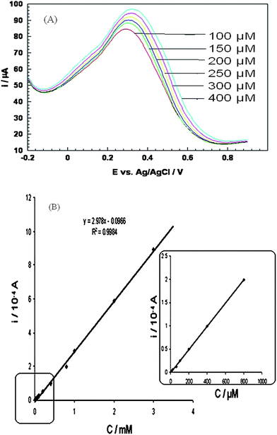 | ||
| Fig. 7 (A) Differential pulse voltammogram of PANI/PAA/MWCNTs modified electrodei.e. system 3 in presence of 100, 150, 200, 250, 200 and 400 μM ascorbic acid, (B) Typical calibration plot. Calibration plot from Fig. 7A. | ||
Conclusions
We describe an easy approach to develop PANI/PAA/MWCNTs modified electrode for ascorbic acid determination. Surface modification of electrode by Nafion-MWCNTs provided hydrophobic and hydrophilic regions which probably improves the crystalline nature of the system. The application of modified electrode for the development of electrochemical sensor for selective detection of ascorbic acid in the presence of dopamine and uric acid was finally explored.Acknowledgements
Authors are highly grateful for the financial support from C.S.I.R., New Delhi and BRNS, DAE.References
- R. H. Baughman, A. A. Zakhidov and W. A. de Heer, Science, 2002, 297, 787 CrossRef CAS.
- L. Q. Rong, C. Y. Q. Y. Qian and X. H. Xia, Talanta, 2007, 72, 819 CrossRef CAS.
- H. Miyagawa, M. Misra and A. K. Mohanty, J. Nanosci. Nanotechnol., 2005, 10, 1593 CrossRef.
- A. P. Alivisatos, Science, 1996, 271, 933 CAS.
- I. Tiwari, K. P. Singh and M. Singh, Russ. J. Gen. Chem., 2009, 75, 2685 CrossRef.
- E. Katz and I. Willner, ChemPhysChem, 2004, 5, 1084 CrossRef CAS.
- A. Merkoc, Microchim. Acta, 2006, 152, 157 CrossRef.
- N. Saito, Y. Usui, K. Aoki, N. Narita, M. Shimizu, K. Hara, N. Ogiwara, K. Nakamura, N. Ishigaki, H. Kato, S. Taruta and M. Endo, Chem. Soc. Rev., 2009, 38, 1897 RSC.
- C. A. Mitchell, J. L. Bahr, S. Arepalli, J. M. Tour and R. Krishnamoorti, Macromolecules, 2002, 35, 8825 CrossRef CAS.
- L. S. Schadler, S. C. Giannaris and P. M. Ajayan, Appl. Phys. Lett., 1998, 73, 3842 CrossRef CAS.
- J. Wang, M. Musameh and Y. Lin, J. Am. Chem. Soc., 2003, 125, 2408 CrossRef CAS.
- A. Liu, I. Honma, M. Ichihara and H. Zhou, Nanotechnology, 2006, 17, 2845 CrossRef CAS.
- A. F. Diaz and J. A. Login, J. Electroanal. Chem., 1980, 111, 111 CrossRef CAS.
- S. A. Chen and H. T. Lee, Macromolecules, 1995, 28, 2858 CrossRef CAS.
- Y. Yang and W. A. Yang, Polym. Adv. Technol., 2005, 16, 24 CrossRef CAS.
- H. Hu, J. L. Cadenas, J. M. Saniger and P. K. Nair, Polym. Int., 1998, 45, 262 CrossRef CAS.
- L. T. Cai and H. Y. Chen, J. Appl. Electrochem., 1998, 28 Search PubMed.
- P. N. Bartlett and E. N. K. Wallace, Phys. Chem. Chem. Phys., 2001, 3, 149 RSC.
- M. C. Yebra-Biurrun, Talanta, 2000, 52, 367 CrossRef CAS.
- E. Kimoto, S. Terada and T. Yamaguchi, Methods Enzymol., 1997, 279, 3 CAS.
- X. Wu, Y. Diao, C. Sun, J. Yang, Y. Wang and S. Sun, Talanta, 2003, 53, 95 CrossRef.
- R. Koncki, T. Lenarczuk, A. Radomska and S. Glab, Analyst, 2001, 126, 1080 RSC.
- J. Facci and R. W. Murray, Anal. Chem., 1982, 54, 772 CrossRef CAS.
- A. Kumar, S. L. P. Hsun and C. S. Ming, Biosens. Bioelectron., 2009, 24, 518 CrossRef.
- M. H. Pournaghi-Azar, H. Razmi-Nerbin and B. Hafezi, Electroanalysis, 2002, 14, 206 CrossRef CAS.
- X. L. Luo, J. J. Xu, W. Zhao and H. Y. Chen, Anal. Chim. Acta, 2004, 512, 57 CrossRef CAS.
- F. Li, C. Tang, S. Liu and G. Ma, Electrochim. Acta, 2010, 55, 838 CrossRef CAS.
- S. M. Chen and K. T. Peng, J. Electroanal. Chem., 2003, 547, 179 CrossRef CAS.
- L. Ming, W. Yangping, L. Dong, Y. Ruirui, X. Jingkun and H. Haohua, Sens. Actuators, B, 2011, 159, 277 CrossRef.
- P. C. Nien, P. Y. Chen and K. C. Ho, Sens. Actuators, B, 2009, 140, 58 CrossRef.
- A. Ambrosi, A. Morrin, M. R. Smyth and A. J. Killard, Anal. Chim. Acta, 2008, 609, 37 CrossRef CAS.
- D. Wen, S. Guo, S. Dong and E. Wang, Biosens. Bioelectron., 2010, 26, 1056 CrossRef CAS.
- D. Manoj, D. Satheesh and J. Santhanalakshmi, Trans. Indian Inst. Met., 2011, 64, 195 CrossRef CAS.
- F. Li, J. Li, Y. Fang, L. Yang and Z. Du, Sens. Actuators, B, 2011, 157, 110 CrossRef CAS.
- A. Kitani, J. Izumi, J. Yanu, Y. Hiromotto and K. Sasaki, Bull. Chem. Soc. Jpn., 1984, 57, 2254 CrossRef CAS.
- X. Lu, Y. Yu, L. Chen, H. Mao, L. Wang, W. Zhang and Y. Wei, Polymer, 2005, 46, 5329 CrossRef CAS.
- Chi and H. Y. Chen, J. Appl. Electrochem., 1998, 28, 161 Search PubMed.
- N. G. R. Mathebe, A. Morrin and E. I. Iwuoha, Talanta, 2004, 64, 115 CrossRef CAS.
- J. Wang, Mustafa Musameh and Yuehe Lin, J. Am. Chem. Soc., 2003, 125, 2408 CrossRef CAS.
- M. E. Jozefowicz, R. Laversanne and H. H. S. Javadi, Phys.Rev., 1989, B39, 12958 Search PubMed.
- B. Sixou, J. P. Travers, C. Barthet and M. Guglielmi, Phys.Rev., 1997, B 56, 4604 Search PubMed.
- J. E. Huang, X. H. Li, J. C. Xu and H. L. Li, Carbon, 2003, 41, 2731 CrossRef CAS.
- S. C. K. Misra, P. Mathur, M. Yadav, M. K. Tiwari, S. C. Garg and P. Tripathi, Polymer, 2004, 45, 8623 CrossRef CAS.
- N. Oyama, Y. Ohnuki, K. Chiba and T. Ohsaka, Chem. Lett., 1983, 12, 1759 CrossRef.
- R. Kostic, D. Rakovic, I. E. Davidova and L. A. Gribov, Phys. Rev. B: Condens. Matter, 1992, 45, 728 CrossRef CAS.
- S. A. Chen and H. T. Lee, Synth. Met., 1992, 47, 233 CrossRef CAS.
- G. A. Rimbu, I. Stamatin, C. L. Jackson and K. Scott, J. of optoelectr. and Adv. Materials, 2006, 8, 670 CAS.
- L. Zhang, Y. Long, Z. Chen and M. Wan, Adv. Funct. Mater., 2004, 14, 693 CrossRef CAS.
- M. Cochet, W. K. Maser, A. M. Benito, M. A. Callejas, M. T. Martínez, J. M. Benoit, J. Schreiber and O. Chauvet, Chem. Commun., 2001, 16, 1450 RSC.
- Luo, X. Wang, J. Li, X. Zhao and F. Wang, Electrochem. Commun., 2007, 9, 1175 CrossRef CAS.
- D. J. Guo and H. U. Li, J. Solid State Electrochem., 2005, 9, 445 CrossRef CAS.
- F. Xu, L. Wang, M. Gao, L. Jin and J. Jin, Talanta, 2002, 57, 365 CrossRef CAS.
- J. J. Xu, Z. H. Yu and H. Y. Chen, Anal. Chim. Acta, 2002, 463, 239 CrossRef CAS.
- L. Joshi, B. Gupta and Rajiv Prakash, Thin Solid Films, 2010, 519, 218 CrossRef CAS.
- C. Peng, J. Jin and G. Z. Chen, Electrochim. Acta, 2007, 53, 525 CrossRef CAS.
- I. G. Casella and M. R. Guascito, Electroanalysis, 1997, 9, 1381 CrossRef CAS.
- S. Slade, S. A. Campbell, T. R. Ralph and F. C. Walsh, J. Electrochem. Soc., 2002, 149, A1556 CrossRef CAS.
- Y. Tang, K. Pan, X. Wang, C. Liu and S. Luo, Microchim. Acta, 2010, 168, 231–237 CrossRef CAS.
- T. Rohani and M. A. Taher, Talanta, 2009, 78, 743 CrossRef CAS.
- T. H. Tsai, T. W. Chen and S. M. Chen, Electroanalysis, 2010, 22, 1655 CrossRef CAS.
- L. Civit, H. M. Nassef, A. Fragoso and C. K. O'Sullivan, J. Agric. Food Chem., 2008, 56, 10452 CrossRef CAS.
- M. Noroozifar, M. Khorasani-Motlagh and A. Taheri, Talanta, 2010, 80, 1657 CrossRef CAS.
- S. Shahrokhian and E. Asadian, Electrochim. Acta, 2010, 55, 666 CrossRef CAS.
- N. F. Atta, M. F. El-Kady and A. Galal, Anal. Biochem., 2010, 400, 78 CrossRef CAS.
- G. Z. Hu, Y. Guo and Q. M. Xue, et al. , Electrochim. Acta, 2010, 55, 2799 CrossRef CAS.
- S. S. Nair, S. A. John and T. Sagara, Electrochim. Acta, 2009, 54, 6837 CrossRef CAS.
Footnote |
| † This article is part of a web theme in Analyst and Analytical Methods on Future Electroanalytical Developments, highlighting important developments and novel applications. Also in this theme is work presented at the Eirelec 2011 meeting, dedicated to Professor Malcolm Smyth on the occasion of his 60th birthday. |
| This journal is © The Royal Society of Chemistry 2012 |
