Environmentally friendly route for the preparation of solvent resistant polyimide nanofiltration membranes
Iwona
Soroko
,
Yogesh
Bhole
and
Andrew Guy
Livingston
*
Department of Chemical Engineering and Chemical Technology, Imperial College London, Exhibition Road, London, UK SW7 2AZ. E-mail: a.livingston@imperial.ac.uk
First published on 13th December 2010
Abstract
Organic Solvent Nanofiltration (OSN) is an emerging membrane separation process with the potential to replace traditional separation techniques. Its advantages include lower energy consumption than alternatives such as distillation, easy up scaling and flexibility. However, manufacturing OSN membranes involves a number of stages contributing towards the discharge of hazardous chemicals as waste. Thus the environmental advantages of employing OSN are to some extent cancelled out by the waste released during OSN membrane production. This paper describes a process for the preparation of polyimide integrally skinned asymmetric OSN membranes with adjustable molecular weight cut off (MWCO). Previously reported methods for producing polyimide based OSN membranes are modified in the presented work without compromising the performance of the membranes. The toxic solvents used to form polymer dope solution, i.e.dimethylformamide (DMF)/1,4-dioxane are replaced by an environmentally friendly dimethyl sulfoxide (DMSO)/acetone solvent system. In order to further diminish the environmental impact, isopropanol was successfully replaced with water in the crosslinking step. Scanning electron microscope images revealed that membranes with spongy matrix without macrovoids were obtained regardless the DMSO/acetone ratio.
1. Introduction
Membrane technology has a range of advantages compared to traditional separation methods such as distillation. It is characterized by low energy consumption, easy integration with other processes as well as up scaling. Benefits derived from applying membrane processes are widely known and now membrane technologies have been established at an impressively large scale.1Nanofiltration is a membrane process which can be applied to the separation of species within the 200–2000 g mol−1 molecular weight range. It has been widely applied to the filtration of aqueous liquids. However, due to the lack of suitable membranes, the application of nanofiltration in organic solvents was still limited. Since then, subsequent development of membranes suitable for Organic Solvent Nanofiltration (OSN) has opened up a wide range of potential applications of nanofiltration for non-aqueous solutions.2 OSN has been successfully applied in a variety of lab scale chemical processes such as catalyst recovery, solvent recycling, chiral separations or ionic liquid separation.3–5 The MAX-DEWAX™ membrane process installed at Exxon Mobil's Beaumont refinery is a first example of large scale application of nanofiltration in organic solvents.6
Polymeric membranes generally fail to maintain their physical integrity in organic solvents because of their tendency to swell or dissolve. However, it is possible to obtain nanofiltration membranes for non-aqueous applications by preparing them from polymer materials that are more solvent resistant. Commercial polyimide (PI) OSN membranes have been shown to give good performance in several organic solvents (e.g.toluene, methanol, ethyl acetate, etc.),7 but polyimides are unstable in some amines8 and have generally poor stability and performance in polar aprotic solvents. See-Toh et al. introduced chemical crosslinking of polyimide with aliphatic diamines as a successful method to obtain PI OSN membranes stable in a range of organic solvents including polar aprotic solvents such as dichloromethane, tetrahydrofuran (THF), N-methylpyrrolidone (NMP) and N,N-dimethylformamide.9 See-Toh et al. reported that control over molecular weight cut off (MWCO)† of PI nanofiltration membranes can be achieved by varying the ratio of the solvent (DMF) to the volatile co-solvent (1,4-dioxane) in the dope solution.10DMF/1,4-dioxane system has been widely used to form OSN membranes as its use provides easy method to obtain asymmetric membranes with a wide range of MWCO and satisfactory fluxes. DMF provides a good solvent-polymer affinity whereas 1,4-dioxane, having less polymer-solvent affinity, acts as a volatile co-solvent. Partial evaporation of 1,4-dioxane during membrane formation as well as its lower solvent power are required to induce asymmetric membrane structure formation. In OSN, especially when more open, porous membranes having higher MWCO are used, compaction problems arise. Compaction is defined as a membrane porous structure collapse upon pressurising and consequently, permeate flux decline. Presence of macrovoid-like membrane matrix structure is often associated with greater compaction.10 Macrovoids have however no impact on rejection.
The OSN membrane manufacturing process required the following steps:
- Polymer dissolution in a solvent mixture (DMF/1,4-dioxane) to obtain polymer dope solution.
- Casting of polymer film upon a backing material.
- Immersion of the cast polymer film in non-solvent bath (typically water).
- Immersion of the membrane in isopropanol (IPA) to remove water from the membrane matrix.
- Immersion of the membrane in the crosslinking solution (1,6-hexamethylenediamine (HDA) in IPA).
- Immersion of the membrane in the fresh IPA to remove residual HDA.
- Immersion of the membrane in the conditioning solution (polyethylene glycol 400 (PEG 400) in IPA).
- Air-drying of the membrane.
The chemicals and reagents used in the preparation of PI based OSN membranes have serious environmental and toxicological problems associated with them. In this work we seek to replace the environmentally harmful solvent composition, i.e.DMF/1,4-dioxane with environmentally friendly solvents, i.e.dimethyl sulfoxide (DMSO) and acetone, whereas the crosslinking step is modified to minimize the high volume use of organic solvents.
According to the U.S. Food and Drug Administration (FDA) solvent classification based on their possible risk to human health, DMSO, and acetone belong to class 3, which is defined as solvents with low toxic potential (solvents with low toxic potential to humans; no health-based exposure limit is needed). DMSO is present naturally in various plants and in the oceans. It is one of the least toxic organic chemicals known, and hence is considered a green solvent.11,12 More importantly, DMSO is much less toxic than the other dipolar aprotic solvents such as DMF, DMAC, and NMP required to dissolve polyimides. DMSO has also been shown to have applications in medicine.13,14
In this study, a less hazardous route of the PI based OSN membrane formation process which would have minimum environmental impact without compromising the separation performance of the existing membranes was investigated.
2. Experimental
2.1. Materials and methods
Nanofiltration experiments. Nanofiltration experiments were carried out in a METcell cross-flow system9 at 30 bar with DMF as a solvent and at 20 °C to determine permeate flux and molecular weight cut off curves of the membranes. Permeate samples for flux measurements were collected at intervals of 1 h, and samples for rejection evaluations were taken after steady permeate flux was achieved. MWCO curves were obtained by using a standard test solution composed of a homologous series of styrene oligomers dissolved in the selected solvent.15 The styrene oligomer mixture contained 1 g L−1 of PS 580 and PS 1050 and 0.01 g L−1 of α-methylstyrene dimer. Concentrations of styrene oligomers in permeate samples were analysed using an Agilent HPLC system with UV/Vis detector set at a wavelength of 264 nm. Separation was accomplished using an ACE 5-C18-300 column (Advanced Chromatography Technologies, ACT, UK). A mobile phase comprising 35 vol% analytical grade water and 65 vol% tetrahydrofuran with 0.1 vol% trifluoroacetic acid was used.
Solvent flux (J) was determined by measuring volume of permeate (V) per unit area (A) per unit time (t) according to the following equation:
 | (1) |
 | (2) |
Rejection (Ri) of styrene oligomers was evaluated applying eqn (3) in which CP,i and CF,i correspond to styrene oligomers concentration in permeate and in feed solution, respectively.
 | (3) |
Scanning electron microscopy (SEM). SEM (TM-1000 Tabletop Microscope, Hitachi High-Technologies) was used to obtain images of cross-sections of the tested membranes. After removing the backing material, membranes were snapped in liquid nitrogen and mounted onto SEM stubs. Applied SEM conditions were: a 5640 μm working distance, Lensmode, an accelerating voltage: 15
![[thin space (1/6-em)]](https://www.rsc.org/images/entities/char_2009.gif) 000 V, an emission current: 91.9 mA and a magnification of 300 times.
000 V, an emission current: 91.9 mA and a magnification of 300 times.
FTIR . In order to confirm successful polyimide crosslinking, a Perkin–Elmer Spectrum One FT-IR spectrometer with a MIRacleTM attenuated total reflection (ATR-Pike Technologies) attachment was used.
Kaiser test. A standard Kaiser test was used to ensure that there is no residual crosslinker (HDA) in the membranes to be used for the elemental analysis. The membranes were washed until the Kaiser test was negative.
Elemental analysis . The extent of crosslinking of the membrane was determined by the elemental analysis (Carlo Erba CE1108 Elemental Analyser at London Metropolitan University).
3. Results and discussions
3.1. Effect of change of the solvents on the properties of the OSN membranes
The prime objective of the present work was to develop a successful method for preparation of PI based OSN membranes. The manufacturing of PI based OSN membranes is a multi-step process accompanied by generation of large amount of hazardous organic waste. To begin with, the aim was to eliminate DMF from the DMF/1,4-dioxane solvent composition commonly used for the formation of the PI OSN membranes and to replace it with less toxic DMSO. The performance of the OSN membranes prepared from DMSO/1,4-dioxane and DMF/1,4-dioxane solvent mixtures are presented in Fig. 1.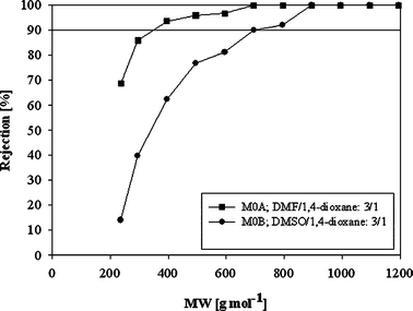 | ||
| Fig. 1 Rejection of PI OSN membranes with respect to the choice of solvent system in the polymer dope solution in DMF and at 30 bar. | ||
Membranes
M0A prepared from 22 wt% PI solution in DMF/1,4-dixane![[thin space (1/6-em)]](https://www.rsc.org/images/entities/char_2009.gif) :
:![[thin space (1/6-em)]](https://www.rsc.org/images/entities/char_2009.gif) 3/1 have MWCO of 350 g mol−1 and flux of 137 L m−2h−1. For comparison, the performance of the membranes prepared from 22 wt% PI solution in DMSO/1,4-dioxane
3/1 have MWCO of 350 g mol−1 and flux of 137 L m−2h−1. For comparison, the performance of the membranes prepared from 22 wt% PI solution in DMSO/1,4-dioxane![[thin space (1/6-em)]](https://www.rsc.org/images/entities/char_2009.gif) :
:![[thin space (1/6-em)]](https://www.rsc.org/images/entities/char_2009.gif) 3/1 has MWCO of 700 g mol−1 and flux of 330 L m−2h−1. These results suggest that DMF can be replaced with DMSO in the formation of PI OSN membranes. As the solvent is an important parameter having significant impact on the PI OSN membrane performance, differences in rejection and flux for the same solvent/co-solvent ratio were expected, and we could reasonably expect that optimisation would result in the ability to achieve similar performance for DMSO/1,4-dioxane and DMF/1,4-dioxane.
3/1 has MWCO of 700 g mol−1 and flux of 330 L m−2h−1. These results suggest that DMF can be replaced with DMSO in the formation of PI OSN membranes. As the solvent is an important parameter having significant impact on the PI OSN membrane performance, differences in rejection and flux for the same solvent/co-solvent ratio were expected, and we could reasonably expect that optimisation would result in the ability to achieve similar performance for DMSO/1,4-dioxane and DMF/1,4-dioxane.
Successful elimination of DMF during membrane preparation was followed by investigating the possibility of replacing toxic 1,4-dioxane with acetone. It was found that the DMSO/acetone system, in a broad range of ratios, is suitable to dissolve Lenzing P84 and form PI OSN membranes. The impact of the DMSO/acetone ratio on rejection of PI membranes is shown in Fig. 2. With increasing concentration of acetone, denser membranes characterized by lower MWCO and lower permeate flux were obtained (Fig. 2, Table 2). Similarly, See-Toh et al. reported that an increase in the ratio of 1,4-dioxane to DMF yields tighter PI OSN membranes with lower MWCO and lower permeate flux.10 However, for the DMSO/acetone system, regardless of the solvents ratio in the dope solution, hardly any macrovoids were formed. This aspect is covered in detail in section 3.2. Membranes prepared from the DMF/1,4-dioxane solvent system were affected by the macrovoid formation when higher DMF concentrations were used.10
| Membrane notation | DMSO/acetone ratio | MWCO/g mol−1 | DMF steady flux Fs/L m−2h−1 | DMF flux decrease DF [%] |
|---|---|---|---|---|
| a DMF/1,4-dioxane. b DMSO/1,4-dioxane. | ||||
| M0A | 3/1a | 350 | 137 | 62 |
| M0B | 3/1b | 700 | 330 | 72 |
| M0C | 1/3a | 330 | 7.0 | 57 |
| M1 | 3/1 | 280 | 17 | 43 |
| M2 | 5/1 | 320 | 51 | 66 |
| M3 | 7/1 | 290 | 120 | 69 |
| M4 | 11/1 | 380 | 129 | 80 |
| M5 | 13/1 | 480 | 171 | 66 |
| M6 | 15/1 | 590 | 214 | 70 |
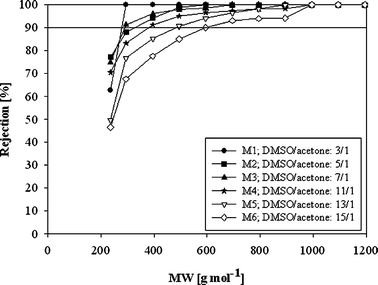 | ||
| Fig. 2 Rejection of PI OSN membranes with respect to the DMSO/acetone ratio in the polymer dope solution in DMF and at 30 bar. | ||
In order to compare the performance of PI OSN membranes prepared from DMSO/acetone and DMF/1,4-dioxane, membranes with similar rejection are compared. Fig. 3 shows the comparison between M0C and M1. Please note that for the DMF/1,4-dioxane system, the share of 1,4-dioxane needs to be higher to obtain a dense membrane, whereas for the DMSO/acetone system the acetone share is relatively low even for dense membranes, as acetone is a strong non-solvent for polyimides.
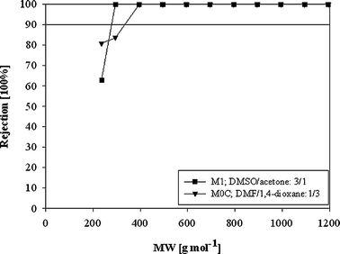 | ||
| Fig. 3 Performance of PI OSN membranes with respect to the solvent composition in the polymer dope solution in DMF at 30 bar. | ||
The analysis of performance of M1 and M0C shows that the membrane prepared from DMSO/acetone exhibits higher flux with comparable rejection compared to the membrane prepared from DMF/1,4-dioxane (Fig. 3, Table 2).
3.2. Effect of change in dope solution solvents on the morphology of the membranes
Fig. 4 presents the cross-sections of PI membranes prepared from dope solutions with varying DMSO/acetone ratios. Regardless of the DMSO/acetone ratio, a spongy membrane matrix was obtained with hardly any macrovoids present (Fig. 4A–F). The high water affinity of DMSO may suggest that membranes with a high number of macrovoids will be formed.16 However, a spongy membrane matrix is obtained. The formation of sponge-like structures in membranes prepared from the PI/DMSO/water system might be associated with a high freezing point (17 °C) of DMSO and high viscosity of PI/DMSO dope solution.16 The absence of macrovoids might be also a consequence of the characteristic thermodynamics and kinetics of the PI/DMSO/water system.16,17 The addition of a non-solvent to the dope solution creates a highly complex, multicomponent system. Its thermodynamic/kinetic behaviour cannot readily be predicted. The impact of the non-solvent addition on the membrane structure is dependent on non-solvent power and volatility, its concentration and specific polymer/solvent interactions.18SEM images (Fig. 4A–E) show that increasing the concentration of acetone, which is a non-solvent for polyimide, did not cause any substantial changes in the membrane matrix morphology. Regardless of the share of acetone, spongy structures with hardly any macrovoids were obtained.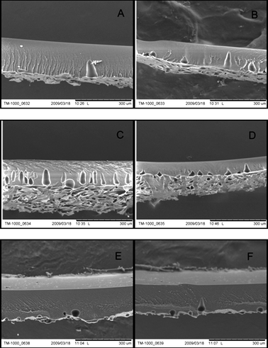 | ||
Fig. 4
SEM pictures of cross-sections of 22 wt% PI membranes prepared from dope solutions with varying DMSO/acetone ratio; A) M1, DMSO/acetone![[thin space (1/6-em)]](https://www.rsc.org/images/entities/char_2009.gif) : :![[thin space (1/6-em)]](https://www.rsc.org/images/entities/char_2009.gif) 3/1 B) M2, DMSO/acetone 3/1 B) M2, DMSO/acetone![[thin space (1/6-em)]](https://www.rsc.org/images/entities/char_2009.gif) : :![[thin space (1/6-em)]](https://www.rsc.org/images/entities/char_2009.gif) 5/1; C) M3, DMSO/acetone 5/1; C) M3, DMSO/acetone![[thin space (1/6-em)]](https://www.rsc.org/images/entities/char_2009.gif) : :![[thin space (1/6-em)]](https://www.rsc.org/images/entities/char_2009.gif) 7/1; D) M4, DMSO/acetone 7/1; D) M4, DMSO/acetone![[thin space (1/6-em)]](https://www.rsc.org/images/entities/char_2009.gif) : :![[thin space (1/6-em)]](https://www.rsc.org/images/entities/char_2009.gif) 11/1; E) M5, DMSO/acetone 11/1; E) M5, DMSO/acetone![[thin space (1/6-em)]](https://www.rsc.org/images/entities/char_2009.gif) : :![[thin space (1/6-em)]](https://www.rsc.org/images/entities/char_2009.gif) 13/1; F) M6, DMSO/acetone 13/1; F) M6, DMSO/acetone![[thin space (1/6-em)]](https://www.rsc.org/images/entities/char_2009.gif) : :![[thin space (1/6-em)]](https://www.rsc.org/images/entities/char_2009.gif) 15/1. 15/1. | ||
Perhaps surprisingly, although spongy, macrovoid-free structures were obtained for all PI membranes regardless the DMSO/acetone ratio, the compaction problem was still observed (Fig. 4, Table 2). This may imply that the presence of macrovoids is not central to the occurrence of membrane compaction phenomenon as it is commonly assumed. We conclude, similarly to our study on the TiO2/PI mixed matrix OSN membranes, that it is rather a collapse of the pores in the top layer as well as pores of the spongy sublayer, or the pore blocking, rather than the presence of macrovoids, that accounts for compaction and flux decrease.19
3.3. Effect of crosslinking medium
The stable performance of the PI OSN membranes in aprotic solvents such as DMF, NMP, DMAc, etc, requires crosslinking of the PI. Crosslinking was previously achieved by treatment with an IPA solution of HDA.9IPA was suggested to swell the membranes, allowing effective diffusion of HDA and subsequent crosslinking of the membranes. However, crosslinking of membranes in IPA demands substantial use of IPA in a number of stages such as washing the membrane before and after crosslinking. In the present work the possibility of crosslinking in aqueous medium was explored as a way of reducing the use of IPA. It has been reported that surface of the polyimide membranes for supported liquid membrane applications can be successfully crosslinked with p-xylenediamine in aqueous solution.20 Moreover, Vanherck et al. have studied reactivity of different polyimides in reaction with a range of diamines dissolved in water coagulation bath.21 The major concern about using water as a crosslinking media was the protonation of HDA in water. Hexanediamine can exist in aqueous solutions in three different forms: +H3N–CH2–CH2–CH2–CH2–CH2–CH2–NH3+, +H3N–CH2–CH2–CH2–CH2–CH2–CH2–NH2, and H2N–CH2–CH2–CH2–CH2–CH2–CH2–NH2. The existence of these forms is highly dependent on the pH of the solution. In the present work the membranes were crosslinked using 1, 2.5, 5 and 10 wt% aqueous solution of HDA, giving solutions with pH values of 11.6, 11.8, 12 and 12.1, respectively. At the pH of crosslinking medium the complete de-protonation of HDA was ruled out with possible existence of mono-protonated HDA (4–1% depending on pH of the crosslinking solution). The FTIR spectra of the membranes treated with aqueous solutions of HDA are presented in Fig. 5. Compared with the original membrane, the signal intensity of imide bands at 1780, 1718 and 1351 cm−1 were significantly attenuated, indicating reduction in the imide bonds. Concomitantly, the amide bands at 1648 and 1534 cm−1 were observed to increase, which further confirms the crosslinking reaction.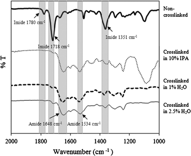 | ||
| Fig. 5 FTIR spectra of the uncrosslinked and crosslinked membranes. | ||
However, the presence of amide bonds can be contributed to the reaction of monoprotonated HDA with PI leading to instability of membranes in DMF. In order to confirm the crosslinking reaction between unprotonated HDA and PI, the treated membranes were tested for the polystyrene oligomer rejection performance in DMF at 30 bar pressure, and results are presented in Fig. 6. Sample discs of membrane M1 were crosslinked in HDA water solution having 10, 5, 2.5 and 1 wt% concentration. Additionally, a reference M1 was crosslinked in a HDA IPA solution of 10 wt%. Crosslinking time was 17 h. Mass of HDA was always used in 20 fold excess to the amount required based on a stoichiometric crosslinking reaction presented in Fig. 7. Changes in concentration were achieved by varying volume of the crosslinking solution.
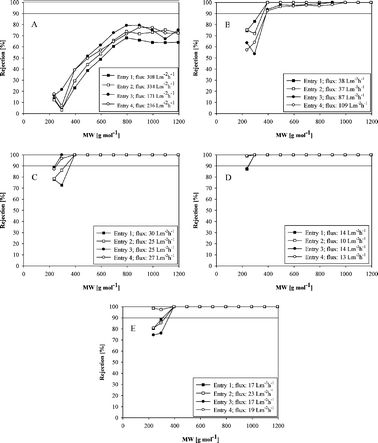 | ||
| Fig. 6 Performance of M1 crosslinked in: A) 10 wt% HDA in H2O, B) 5 wt% HDA in H2O, C) 2.5 wt% HDA in H2O, D) 1 wt% HDA in H2O, E) 10 wt% HDA in IPA. Filtration was conducted in DMF at 30 bar. Each entry corresponds to a tested coupon cut from an independently prepared membrane. | ||
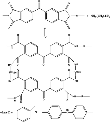 | ||
| Fig. 7 Structure of Lenzing P84 polyimide chemically crosslinked with HDA. | ||
The performance in terms of rejection and flux has been proven to be dependent on the concentration of HDA in water (Fig. 6). Membranes crosslinked in 10 wt% water solution showed significantly decreased rejection and increased flux as compared to the reference membrane crosslinked in IPA (Fig. 6 A and 6 E). Worsen rejection and higher flux were also observed when 5 wt% water solution was used (Fig. 6 B). On the surface of the membranes crosslinked in 10 and 5 wt% HDA in water, a few small brown spots were observed- more in case of the membrane crosslinked in 10 wt% solution. The possible cause for this etching of the membrane may be attributed to the degradation of the polymer due to high concentration of HDA. Although the coupons for the filtration tests were cut from spot-free regions, the performance was found to have deteriorated. Rejections comparable to the reference membrane with simultaneously improved DMF flux were observed for membranes crosslinked in 2.5% water solution (Fig. 6 C). When 1 wt% water solution was used, the membrane was characterized by a slightly higher rejection and lower DMF flux (Fig. 6 D). The surfaces of the membranes crosslinked in 2.5 and 1 wt% HDA in water were free of brown spots.
In order to ensure the long term stability of membranes crosslinked in aqueous medium, the membranes M1 crosslinked in 1 and 2.5 wt% solutions of HDA in water were also tested for a long term filtration (7 days) in DMF at 30 bar. First permeate samples were collected after 5 h of the filtration. From that time on, the permeate samples were collected at intervals of 24 h. No changes in rejections were registered even after day 7.
To investigate the degree of crosslinking of the membranes M1 crosslinked in 1 wt% and 2.5 wt% solutions of HDA in water, and for the reference membrane crosslinked in IPA, elemental analyses were conducted. Fig. 7 shows the assumed structure of the crosslinked P84 when the crosslinking reaches completion.
The theoretical C/N ratio (% mass) can be calculated in the crosslinked P84 as 6.7. The elemental analysis results have given the following values of C/N ratio: 6.6; 6.5 and 6.6 for M1 crosslinked in 1 and 2.5 wt% solutions of HDA in water and the reference membrane crosslinked in IPA, respectively. The C/N ratio results confirm the equivalent degree of crosslinking of the polyimide with HDA in water in comparison to HDA in IPA, and they also suggest complete crosslinking.
Based on the results gathered, it can be concluded that IPA, which was until now widely used as the crosslinking medium for PI OSN, can be replaced with water. In order to ensure that the performance of the membranes is not affected by the degradation reactions, a maximum concentration of 2.5 wt% of HDA in H2O is recommended.
3.4. Environmental impact of the change in the PI OSN membrane formation procedure
To summarize, the advantage in terms of the environmental impact reduction of our PI membrane formation procedure is the following:- Formation of the dope solution waste with environmentally friendly chemicals (DMSO and acetone instead of DMF and 1,4-dioxane).
- Significant reduction in the amount of IPA (removal of two washing steps present in the conventional procedure, i.e. before crosslinking and after crosslinking, and changing IPA for water as the crosslinking medium). Based on the conventional lab scale process, 5.7 L of IPA was used per 1 m2 of PI OSN membrane. This is now reduced to 2.3 L of IPA per 1 m2 of membrane which accounts for almost 60% reduction of the use of IPA.
We believe that toxic polar aprotic solvents such as NMP and DMF could be successfully replaced with benign DMSO in further membrane separation areas such as reverse osmosis (RO) process having a far greater environmental impact due to the market for its application in water desalination. In RO, cellulose acetate membranes (CA) were predominantly chosen until the development of new thin film composite (TFC) RO membranes in 1972. Most TFC membranes are prepared via coating of a cross-linked aromatic polyamide film on a porous support such as polysulfone (PSf), which appears to be the most popular polymer for TFC support.1,22 To prepare PSf support, the PSf is dissolved in NMP or DMF and a porous film is obtained by phase inversion method.22–26 As DMSO is a good solvent for PSf, it could be researched as a less toxic alternative for TFC support preparation.27,28
4. Conclusions
Polyimide membranes applicable in organic solvent nanofiltration were prepared. A highly toxic solvent composition, i.e.DMF/1,4-dioxane, used to prepare polymer dope solution, was successfully replaced with an environmentally friendly solvent mixture of DMSO/acetone. Variation of DMSO/acetone ratio achieved a shift in rejection curves, thus allowing engineering of the PI OSN membranes to meet specific requirements for different applications. SEM pictures revealed that regardless of the DMSO/acetone ratio, a spongy, macrovoid-free membrane matrix was formed. Surprisingly, the absence of macrovoids did not improve the membrane compaction resistance, which questions the common assumption about the link between the presence of macrovoids and the compaction phenomenon. PI OSN membranes prepared from DMSO/acetone have similar performance in terms of rejection compared to PI OSN membranes prepared from DMF/1,4-dioxane, with the advantage of higher DMF flux, macrovoid-free structure and elimination of toxic organic solvents in the membrane preparation step. The study has shown that isopropanol, previously used as a crosslinking medium, can be successfully replaced by water without compromising membrane performance.Acknowledgements
The authors wish to acknowledge the 6th Framework Programme of the European Commission Marie Curie Initiative for funding a studentship (contract number: MRTN-CT-2006-036053-Insolex) for I. Soroko and Stephen Boyer from London Metropolitan University for the running of the samples for the elemental analysis.References
- R. W. Baker, in Membrane technology and applications, ed. Wiley, 2nd edn, 1994 Search PubMed.
- A. Livingston, L. Peeva, S. J. Han, D. Nair, S. S. Luthra, L. S. White, L. M. F. Santos and Adv, Membr. Tech., 2003, 984, 123–141 Search PubMed.
- S. Han, H. T. Wong and A. Livingston, Chemical Engineering Research & Design, 2005, 83(A3), 309–316 Search PubMed.
- H. T. Wong, Y. H. See-Toh, F. C. Ferreira, R. Crook and A. G. Livingston, Chem. Commun., 2006, 19, 2063–2065 RSC.
- H. T. Wong, C. J. Pink, F. C. Ferreira and A. G. Livingston, Green Chem., 2006, 8, 373–379 RSC.
- L. S. White and A. R. Nitsch, J. Membr. Sci., 2000, 179, 267–274 CrossRef CAS.
- P. Silva, S. J. Han and A. G. Livingston, J. Membr. Sci., 2005, 262, 49–59 CrossRef CAS.
- M. A. M. Beerlage, Ph.D. Thesis, University of Twente, 1994.
- Y. H. See-Toh, F. W. Lim and A. G. Livingston, J. Membr. Sci., 2007, 301, 3–10 CrossRef.
- Y. H. See-Toh, M. Silva and A. G. Livingston, J. Membr. Sci., 2008, 324, 220–232 CrossRef CAS.
- W. M. Nelson, in Green solvents for chemistry: perspectives and practice, ed. Oxford University Press, 2003 Search PubMed.
- J. Li, C Limberakis, D. Pflum in Modern organic synthesis in the laboratory, ed. Oxford University Press, 2007 Search PubMed.
- N. David, Annual Review of Pharmacology, 1972, 12, 353–374 Search PubMed.
- N. Kharasch and B. S. Thyagarajan, Annals of the New York Academy of Sciences, 2006, 391–402.
- Y. H. See-Toh, X. X. Loh, K. Li, A. Bismarck and A. G. Livingston, J. Membr. Sci., 2007, 291, 120–125 CrossRef CAS.
- J. H. Kim, B. R. Min, J. Won, H. C. Park and Y. S. Kang, J. Membr. Sci., 2001, 187, 47–55 CrossRef CAS.
- L. J. Wang, Z. S. Li, Z. J. Ren, S. G. Li and C. Z. Jiang, J. Membr. Sci., 2006, 275, 46–51 CrossRef CAS.
- P. Vandezande, X. Li, L. E. M. Gevers and I. F. J. Vankelecom, J. Membr. Sci., 2009, 330, 307–318 CrossRef CAS.
- I. Soroko and A. G. Livingston, J. Membr. Sci., 2009, 343, 189–198 CrossRef CAS.
- Q. Yang, T. S. Chung, Y. C. Xiao and K. Y. Wang, Chem. Eng. Sci., 2007, 62, 1721–1729 CrossRef CAS.
- K. Vanherck, A. Cano-Odena, G. Koeckelberghs, T. Dedroog and I. Vankelecom, J. Membr. Sci., 2010, 353, 135–143 CrossRef CAS.
- A. K. Ghosh and E. M. V. Hoek, J. Membr. Sci., 2009, 336, 140–148 CrossRef CAS.
- C. K. Kim, J. H. Kim, I. J. Roh and J. J. Kim, J. Membr. Sci., 2000, 165, 189–199 CrossRef CAS.
- L. Li, S. B. Zhang, X. S. Zhang and G. D. Zheng, J. Membr. Sci., 2007, 289, 258–267 CrossRef CAS.
- US Pat., 4,529,646, 1985.
- US Pat., 3,926,798, 1975.
- M. Temtem, T. Casimiro and A. Aguiar-Ricardo, J. Membr. Sci., 2006, 283, 244–252 CrossRef CAS.
- US Pat., 4,874,522, 1989.
Footnote |
| † MWCO is obtained by interpolation of a plot of rejection versus molecular weight of solutes. The molecular weight corresponding to a rejection of 90% is the MWCO. |
| This journal is © The Royal Society of Chemistry 2011 |
