Nanospheres of silver nanoparticles: agglomeration, surface morphology control and application as SERS substrates†
Xiao Shuang
Shen
,
Guan Zhong
Wang
*,
Xun
Hong
and
Wei
Zhu
Hefei National Laboratory for Physical Sciences at Microscale, and Department of Physics, University of Science and Technology of China, Hefei, 230026, Anhui, P. R. China. E-mail: gzwang@ustc.edu.cn; Fax: +86-551-3606266; Tel: +86-551-3603323
First published on 30th June 2009
Abstract
This paper reports a high-yield synthesis of Ag nanospheres made up of primary nanoparticles. The size of the silver nanospheres can be controlled by changing the concentration of poly(vinylpyrrolidone) (PVP) which acts as a stabilizer. In addition, the surface morphology of the nanospheres can be well controlled through controlling the shape of primary Ag nanoparticles by introducing a small quantity of ionic capping agents in the solution. Different surface morphologies of Ag nanospheres lead to different surface plasmon resonance (SPR) and surface-enhanced Raman scattering (SERS) properties. The SERS property of the nanospheres used as substrates is very sensitive to the nanoscale characteristics of the surfaces, and the nanospheres with sharp tips on their surface exhibit much better Raman scattering enhancement than non-agglomerated spherical Ag nanoparticles.
1. Introduction
Shape control of metal nanostructures is a promising strategy to tailor their physical and chemical properties.1 For example, computational work and experimental results have shown that the properties of surface plasmon resonance (SPR) and surface-enhanced Raman scattering (SERS) of silver and gold nanoparticles highly depend on their shape.2–6 Up to date, a variety of metal nanostructures with well-defined morphology have been obtained, eg, cubes,7 octahedrons,8,9 rods,10 and plates.11,12 Recently, metal nanostructures with complex three-dimensional (3D) surface morphology, which are often referred to as nanoflowers13 or nanostars14 in literature, have received considerable attention due to their excellent performance as catalysts15 and SERS substrates.16Ag nanocubes with sharp corners or tips have higher SERS enhancement compared to truncatesd ones.17 Further, for a metal nanostar, the hybridization of plasmons of the core and tips could dramatically increase the excitation cross section and the electromagnetic field enhancements of the tip plasmons, which results in better SERS performance.18Capping agents are widely used in nanoparticle synthesis for the purpose of stabilizing nanoparticles in solution. Insufficiently high concentration of capping agents would lead to agglomeration of nanoparticles, which is a situation the researchers tried to avoid in past. However, it has been recently proved to be an effective method for synthesizing branched nanoparticles through reducing the capping agent concentration and then triggering the agglomeration of primary nanoparticles.19,20 But this method suffers from lack of refined control on the surface morphology of the branched nanoparticles because capping agents not only control the agglomeration but also shape the nanoparticles. How to well control the surface morphology and thus optimize the SERS properties of the nanostructure is an open question.14
Here, we report high-yield, controlled synthesis of Ag nanospheres that are formed by agglomeration of primary Ag nanoparticles. In the synthesis, AgNO3 was reduced by sodium ascorbate in the presence of PVP with low concentration. The size of the Ag nanospheres is controlled by the concentration of PVP. As a polymer with a long chain, the major role of PVP in the synthesis is to control the Ag nanoparticles agglomeration rather than affect the shape of the small primary Ag nanoparticles.21,22 Furthermore, the morphology of the nanospheres is modulated by controlling the shape of primary Ag nanoparticles through introducing a small quantity of ionic capping agents, sodium citrate or sodium dodecyl sulfate. When the Ag nanospheres were applied as SERS substrates, we found that nanospheres with sharper tips on the surface have excellent Raman scattering enhancement.
2. Materials and methods
Materials
Silver nitrate (AgNO3), poly(vinylpyrrolidone) (PVP, Mw ∼ 40![[thin space (1/6-em)]](https://www.rsc.org/images/entities/char_2009.gif) 000), sodium ascorbate, sodium citrate and sodium dodecyl sulfate (SDS) were obtained from Sinopharm Chemical Reagent Co. Ltd. All chemicals were introduced as purchased without further purification. All aqueous solutions of AgNO3, PVP, sodium ascorbate, sodium citrate, and SDS were freshly prepared before use.
000), sodium ascorbate, sodium citrate and sodium dodecyl sulfate (SDS) were obtained from Sinopharm Chemical Reagent Co. Ltd. All chemicals were introduced as purchased without further purification. All aqueous solutions of AgNO3, PVP, sodium ascorbate, sodium citrate, and SDS were freshly prepared before use.
Method
In a typical synthesis, PVP (0.0490 g) was dissolved in 5 mL of deionized water. The solution was put in a 30 °C water bath under magnetic stirring. Then 3 mL aqueous solution of AgNO3 (0.0239 g) was added rapidly. Five minutes later, 3 mL aqueous of sodium ascorbate (0.0099 g) was added to the mixtures rapidly. The solution was allowed to react for 5 min at 30 °C under magnetic stirring.Raman measurement
For preparation of SERS substrates, 1 mL of reaction solution was taken out and centrifuged. The precipitate was washed with deionized water three times, and then redispersed in 100 μL of deionized water. SERS substrates were prepared by dropping 25 μL of the aqueous sol on a 4 × 4 mm2Si wafer. After the solution completely dried in air, the substrates were immersed in 5 mL ethanol to further remove the residual capping agents. According to our SEM observations, the Ag nanospheres are distributed homogeneously on the substrates. Then the substrates were immersed in 1 μM aqueous solution of rhodamine 6G (R6G) for 1 h. The samples were then taken out, rinsed with deionized water, and dried in air. The Raman instrument used in this study was in confocal configuration (LABRAM-HR) and excited by an Ar laser (514 nm). The laser beam was focused on the sample in a size of about 2 μm. The acquisition time was 1 s for each spectrum. For each sample, we took three SERS spectra in different positions of the substrate and then averaged them.3. Results and discussion
In the agglomeration of primary Ag nanoparticles, the concentration of PVP can significantly affect the size of the final Ag nanospheres. We begin our experiments with 8 mM PVP. The SEM image of the products is shown in Fig. 1a. The silver nanospheres obtained are about 500 nm in diameter and with a rough surface morphology. It could easily be seen that these nanospheres are formed through agglomeration of primary nanoparticles with tens of nanometers in diameter (inset of Fig. 1a). These observations are further confirmed by the TEM image (Fig. 1b). Most of the tips on the nanosphere surface are lower than 50 nm, which is determined by the size and shape of primary nanoparticles. A selected area electron diffraction (SAED) pattern shows that the Ag nanospheres have a polycrystalline structure (inset of Fig. 1(b)), which is consistent with the fact that these nanospheres are formed through agglomeration of primary nanoparticles. The agglomeration of primary nanoparticles could be controlled by changing the concentration of PVP. When the concentration of PVP was increased to 40 mM, the diameters of the silver nanospheres were reduced to about 200 nm, as shown in Fig. 1c. When the concentration of PVP was further increased to 200 mM, silver nanospheres with further reducing diameters along with some unaggregated primary nanoparticles could be obtained (Fig. 1d). It is believed that PVP can play the role of stabilizing nanoparticles through adsorption onto the particle surface and steric effect when its concentration is sufficiently high.21,22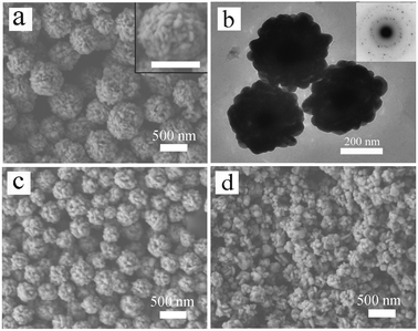 | ||
| Fig. 1 (a) SEM image and (b) TEM image of the sample obtained with 8 mM PVP (sample 1). The inset of (a) shows an enlarged SEM image of a single Ag nanosphere and the inset of (b) shows the SAED pattern taken from a single Ag nanosphere. The scale bar in the inset of (a) represents 500 nm. (c) and (d) SEM images of the samples obtained with other PVP concentration: (c) 40 mM (sample 2) and (d) 200 mM. | ||
Contrary to PVP, sodium citrate can affect the morphology of the nanospheres rather than their size. We found that introducing a small quantity of ionic capping agents could significantly change the surface morphology of Ag nanospheres. Sodium citrate is an ionic capping agent that is widely used to stabilize nanoparticles in a liquid-phase synthesis of Ag nanoparticles.23Fig. 2a shows a SEM image of the products obtained with addition of 50 μL of 12.5 mM sodium citrate while other experimental conditions were kept the same as in Fig. 1c. The surface morphology of the Ag nanospheres suggests that the nanospheres are agglomerated of silver nanoplates. This plate-like morphology became much clearer when the amount of sodium citrate was increased to 100 μL (Fig. 2b and the inset). Fig. 2c shows a TEM image of these nanospheres, in which the plate-like morphology could be observed (marked with arrows in Fig. 2c). When the amount of sodium citrate was further increased to 200 μL, broken Ag nanospheres along with some silver nanoplates were obtained (Fig. S1†). It is worth noting that the molar ratio of sodium citrate and PVP used here is about 0.006. Different from PVP, sodium citrate in the solution induces the formation of thin silver nanoplates which agglomerate and thus form nanospheres with rims of nanoplates on the surface. It is believed that citrate ions have a great influence on the particle growth at early stages by complexing with positively charged Ag2+ dimers.23
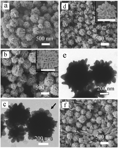 | ||
| Fig. 2 SEM and TEM images of the samples obtained with 40 mM PVP and different concentrations of ionic capping agents: (a) 50 μL of 12.5 mM sodium citrate (sample 3); (b) and (c) 100 μL of 12.5 mM sodium citrate (sample 4); (d) and (e) 100 μL of 12.5 mM SDS (sample 5); and (f) 600 μL of 12.5 mM SDS (sample 6). The insets of (b) and (d) show enlarged SEM images of the corresponding nanospheres and the scale bars in the insets represent 500 nm. | ||
To further modify the surface morphology of Ag nanospheres, experiments with sodium dodecyl sulfate (SDS), another kind of ionic capping agents were also conducted. The SEM image of the products obtained with 100 μL of 12.5 mM SDS (other experimental conditions were the same as that of the sample shown in Fig. 1c) is shown in Fig. 2d. Compared to the Ag nanospheres shown in Fig. 1c, the Ag nanospheres shown in Fig. 2d have much rugged surface morphology, or in other words, they have sharper tips on surface, which could be attributed to the morphological change of the primary nanoparticles. To show the surface features more clearly, TEM image of this sample are given in Fig. 2e. Different from the sample shown in Fig. 1b, most of the tips on the nanosphere surface here are higher than 100 nm. When the amount of SDS was increased to 600 μL, Ag nanospheres made up of smaller primary nanoparticles were obtained (Fig. 2f). In this case, some triangular and hexagonal nanoplates could also be observed in the SEM image.
The samples were characterized by XRD. The peaks in the XRD patterns (Fig. 3) can be assigned to diffraction from (111), (200), (220) and (311) planes of face-centered cubic Ag, respectively. This result shows that all of the samples are composed of pure crystalline Ag. In addition, there is a common feature in these XRD patterns. Namely, the ratios between the intensity of (111) and (200) diffraction peaks are all higher than the conventional value (3.5∼7.4 versus 2.5), indicating the enrichment of {111} crystalline planes in all of Ag nanospheres. Similar phenomena have also been observed in flower-like Ag16 and Au24nanoparticles.
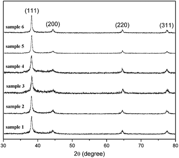 | ||
| Fig. 3 XRD patterns of the samples. | ||
We divide the silver nanospheres into three types according to their surface morphology, as shown in Fig. 4. The type I nanospheres have a relatively lower surface roughness, which includes the samples shown in Fig. 1a (sample 1), 1c (sample 2) and 2f (sample 6). The samples shown in Fig. 2a (sample 3) and 2b (sample 4) are type II nanospheres which have plate-like surface morphology. The sample shown in Fig. 2d (sample 5) belongs to type III nanospheres. Compared to type I nanospheres, the type III nanospheres have more rough surfaces, and namely, have sharper edges and corners. We will see below these three types of nanospheres have different SPR/SERS properties.
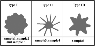 | ||
| Fig. 4 Schematic illustration of the three types of Ag nanospheres. | ||
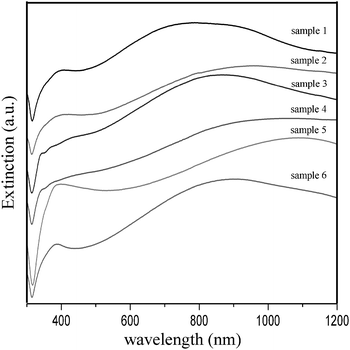
Fig. 5 shows the UV-Vis extinction spectra taken from the aqueous solutions of these Ag nanospheres. For type I (sample 1, sample 2 and sample 6) and type III (sample 5) nanospheres, the corresponding spectra exhibit a short-wavelength SPR band around 390 nm and a long-wavelength SPR band in the near infrared region. The computational work has revealed that the plasmon modes of a nanostar are formed by hybridization of plasmons associated with the core and the tips, and the low-energy bonding nanostar plasmons are primarily composed of tip plasmons but with a finite contribution of the core plasmons.18 For type II nanospheres, the long-wavelength SPR peak still remains, but the short-wavelength SPR peak is divided into several small peaks, which likely results from the geometric anisotropy of the plate-like surface morphology of the nanospheres.25
One of the major objectives of the present study is to prepare and optimize SERS-active substrates. We studied the performance of the samples in SERS applications using R6G as a target molecule. Due to the complex surface morphology of the Ag nanospheres, it is difficult to calculate an accurate enhancement factor. For comparison, nonagglomerated spherical Ag nanoparticles with an average diameter of 30 nm were used as a reference sample (sample 7) (Fig. S2 in the ESI†). Fig. 6 shows the SERS spectra obtained from the samples (sample 1 to 7) treated in 1 μM R6G with the 514-nm excitation. The Raman bands at about 1651, 1574, 1509, 1363, 1312, 1182, and 1129 cm−1 can be attributed to R6G and agree well with literature reports.26 The type III nanospheres (sample 5) exhibit the highest enhancement efficiency. Their SERS intensity of the peak at 1651 cm−1 is about sixteen times stronger than that from 30 nm Ag nanoparticles (sample 7), while only about two times difference is observed for sample 1 which gives the strongest enhancement among type I nanospheres. It indicates that type I nanospheres and sample 7 give the same order enhancement. To our surprise, type II nanospheres exhibit the weakest Raman activity among all the samples, although they have the largest surface–volume ratio.
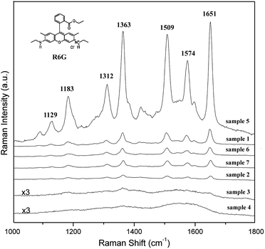 | ||
| Fig. 6 SERS spectra of 1 μM R6G molecules obtained from Ag nanospheres with different surface morphology. For comparison, 30-nm Ag nanoparticles were used as a reference sample (sample 7). | ||
It is reported that SERS-active particles must possess a length scale in the range of 20–100 nm.27 Particles below or above this size produce a weaker signal. For type I nanospheres, the size is in the range of 200–500 nm, which is much bigger than the optimum length scale. However, we found the type I nanospheres could serve as a SERS-active substrate as good as 30-nm Ag nanoparticles. This result could be understood in terms of the fact that this type of samples have small scale roughness on their surface and SERS is a very local phenomenon occurring at tips or in the tiny cavities on the substrate where there are potential “hot” spots for local near-field enhancement effects.28 Compared to type I Ag nanospheres, type III Ag nanosphers have sharper tips, which results in better SERS enhancement. It is well known that the SERS intensity is proportional to the fourth power of the gain in electromagnetic field caused by the nanostructure. For metal nanostructures with sharp edges or tips, the local value of |E|2 could be more than 500 times that of the applied field.29 The strong SERS enhancement for type III sample can be attributed to the nanoscale roughness on the surfaces of Ag nanospheres.
High surface ratio and rich sharp edges and tips on the surface of a substrate generally benefit the SERS property. However, although type II Ag nanospheres have higher surface areas and more sharp edges compared to type I Ag nanospheres, their Raman scattering enhancement is relatively weaker. This result can be attributed to the surface features of the type II nanospheres composed of the plate-like primary Ag nanoparticles, which is greatly different to the other two types of samples. It has been reported Ag nanoplates with size 100 – 300 nm exhibit weaker enhancement compared to wires or spheres.30 Jana et al. also observed that platelets with size above 100 nm produce a weaker signal.31 Our results show that the SERS properties are very sensitive to the nanoscale characteristics of a surface.
4. Conclusion
In summary, Ag nanospheres with complex surface morphology are formed by the agglomeration of Ag nanoparticles. The size and surface morphology of the nanospheres can be well controlled by changing the concentration of PVP and introducing a small quantity of ionic capping agents, respectively. In our experiments, PVP was used as a stabilizer, while ionic capping agents were used as shape-directing agents. The SERS property of the nanospheres used as substrates is very sensitive to the nanoscale characteristics of the surfaces, and the nanospheres with sharp tips on their surface exhibit much better Raman scattering enhancement than non-agglomerated spherical Ag nanoparticles.Acknowledgements
This work was supported by Natural Science Foundation of China (Grant No. 10574122, 50772110, 50721091), the National Basic Research Program of China (2006CB922000, 2007CB925202, 2009CB939901), and KJCX2.YW.W06-3 of CAS.References
- A. R. Tao, S. Habas and P. Yang, Small, 2008, 4, 310 CrossRef CAS.
- C. J. Orendorff, L. Gearheart, N. R. Jana and C. J. Murphy, Phys. Chem. Chem. Phys., 2006, 8, 165 RSC.
- S. Mahajan, M. Abdelsalam, Y. Suguwara, S. Cintra, A. Russell, J. Baumberg and P. Bartlett, Phys. Chem. Chem. Phys., 2007, 9, 104 RSC.
- M. A. El-Sayed, Acc. Chem. Res., 2001, 34, 257 CrossRef CAS.
- I. O. Sosa, C. Noguez and R. G. Barrera, J. Phys. Chem. B, 2003, 107, 6269 CrossRef CAS.
- Z. Tian, Z. yang, B. Ren, J. Li, Y. Zhang, X. Lin, J. Hu and D. Wu, Faraday Discuss., 2006, 132, 159 RSC.
- Y. Sun and Y. Xia, Science, 2002, 298, 2176 CrossRef CAS.
- A. Tao, P. Sinsermsuksakul and P. Yang, Angew. Chem., Int. Ed., 2006, 45, 4597 CrossRef CAS.
- C. Li, K. L. Shuford, Q.-H. Park, W. Cai, Y. Li, E. J. Lee and S. O. Cho, Angew. Chem., Int. Ed., 2007, 46, 3264 CrossRef CAS.
- C. J. Murphy, A. M. Gole, S. E. Hunyadi and C. J. Orendorff, Inorg. Chem., 2006, 45, 7544 CrossRef CAS.
- R. Jin, Y. W. Cao, C. A. Mirkin, K. L. Kelly, G. C. Schatz and J. G. Zheng, Science, 2001, 294, 1901 CrossRef CAS.
- R. Jin, Y. C. Cao, E. Hao, G. S. Métraux, G. C. Schatz and C. A. Mirkin, Nature, 2003, 425, 487 CrossRef CAS.
- J. Xie, Q. Zhang, J. Y. Lee and D. I. C. Wang, ACS Nano, 2008, 2, 2473 CrossRef CAS.
- C. G. Khoury and T. Vo-Dinh, J. Phys. Chem. C, 2008, 112, 18849 CAS.
- X. Teng, S. Maksimuk, S. Frommer and H. Yang, Chem. Mater., 2007, 19, 36 CrossRef CAS.
- L. Lu, A. Kobayashi, K. Tawa and Y. Ozaki, Chem. Mater., 2006, 18, 4894 CrossRef CAS.
- J. M. McLellan, A. Siekkinen, J. Chen and Y. Xia, Chem. Phys. Lett., 2006, 427, 122 CrossRef CAS.
- F. Hao, C. L. Nehl, J. H. Hafner and P. Nordlander, Nano Lett., 2007, 7, 729 CrossRef CAS.
- A. Narayanaswamy, H. Xu, N. Pradhan, M. Kim and X. Peng, J. Am. Chem. Soc., 2006, 128, 10310 CrossRef CAS.
- A. Narayanaswamy, H. Xu, N. Pradhan and X. Peng, Angew. Chem., Int. Ed., 2006, 45, 5361 CrossRef CAS.
- B. Wiley, Y. Sun, B. Mayers and Y. Xia, Chem.–Eur. J., 2005, 11, 454 CrossRef CAS.
- B. Lim, M. Jiang, J. Tao, P. H. C. Camargo, Y. Zhu and Y. Xia, Adv. Funct. Mater., 2009, 19, 189 CrossRef CAS.
- Z. S. Pillai and P. V. Kamat, J. Phys. Chem. B, 2004, 108, 945 CrossRef CAS.
- G. H. Jeong, Y. W. Lee, M. Kim and S. W. Han, J. Colloid Interface Sci., 2009, 329, 97 CrossRef CAS.
- I. Pastoriza-Santos and L. M. Liz-Marzán, J. Mater. Chem., 2008, 18, 1724 RSC.
- S. Nie and S. R. Emory, Science, 1997, 275, 1102 CrossRef CAS.
- H. Ko, S. Singamaneni and V. V. Tsukruk, Small, 2008, 4, 1576 CrossRef CAS.
- L. H. Qian, X. Q. Yan, T. Fujita, A. Inoue and M. W. Chen, Appl. Phys. Lett., 2007, 90, 153120 CrossRef.
- K. L. Kelly, E. Coronado, L. L. Zhao and G. C. Schatz, J. Phys. Chem. B, 2003, 107, 668 CrossRef CAS.
- J. Zhang, X. Li, X. Sun and Y. Li, J. Phys. Chem. B, 2005, 109, 12544 CrossRef CAS.
- N. R. Jana and T. Pal, Adv. Mater., 2007, 19, 1761 CrossRef CAS.
Footnote |
| † Electronic supplementary information (ESI) available: SEM image of the samples obtained with 200 μL of 12.5 mM sodium citrate and UV-Vis extinction spectra taken from the aqueous solution of 30-nm Ag nanoparticles (sample 7). See DOI: 10.1039/b904712c |
| This journal is © the Owner Societies 2009 |

