Li ion kinetic studies on spinel cathodes, Li(M1/6Mn11/6)O4 (M = Mn, Co, CoAl) by GITT and EIS
K. M.
Shaju
,
G. V.
Subba Rao
and
B. V. R.
Chowdari
*
Department of Physics, National University of Singapore, Singapore 119260. E-mail: phychowd@nus.edu.sg
First published on 13th November 2002
Abstract
Pristine and substituted spinels, Li(M1/6Mn11/6)O4 (M = Co1/6, Co1/12Al1/12) were prepared and their cathodic performance up to 80 cycles at ambient temperature and at 50 °C and the Li ion kinetic parameters obtained by galvanostatic intermittent titration technique (GITT) at ambient temperature and 50 °C and electrochemical impedance spectroscopy (EIS) at ambient temperature up to 80 cycles were compared to understand the improved performance observed for the doped spinels. The apparent Li diffusion coefficient (DLi) obtained from GITT in the voltage range of operation of the cell (3.5–4.3 V vs. Li) at ambient temperature and 50 °C is in the range 1 × 10⁻⁹–10−10 cm2 s−1 for M = Mn, Co and (Co,Al). The DLivs. voltage plots show indication of suppression of two-phase formation in doped spinels. Distinct changes in the EIS-derived parameters and the DLi values in the compounds with M = Co, (Co,Al) as compared to LiMn2O4 lead to the conclusion that the observed cycling stability in the doped spinels is contributed by the Li ion kinetics in addition to the suppression of the structural changes and associated material dissolution.
Introduction
Lithium manganese oxide, LiMn2O4 with the cubic spinel structure, has been studied extensively as a 4 V cathode material for lithium (Li) ion batteries.1–6 To improve its cycling performance, especially at elevated temperature (≥50 °C), several approaches such as doping at the Mn site, surface modification, and various preparatory conditions have been shown to be successful.1–17 The partial substitution of Mn as Li(M,Mn)2O4, (M = Li, Co, Cr, Al, (Co,Al), (Co,Cr), Ni, Mg) at the 16d site is known to increase the average Mn-oxidation state, enabling the compound to be more tolerant to Jahn–Teller distortion, and an improved cathodic performance is observed.5–17 The latter is also ascribed to the stronger M–O (M = Co, Cr, Al) bond strength compared to that of the Mn–O bond in the spinel structure.5,10–14 The observed reduction in the initial charge–discharge capacity proportional to the amount of the substituent M leads to the conclusion that the Mn3+ ions in the lattice are replaced and the M ion is electrochemically inactive in the voltage range of operation, 3.5–4.3 V vs. Li.5,10–14The main reasons for the capacity fading in LiMn2O4-type cathodes were ascribed to structural change and Mn dissolution on cycling the cells especially at high temperatures.3–5,7–9,16–21 The increased impedance contribution of the LiMn2O4 electrode with cycling was also correlated with the observed capacity fading in spinel compounds.22,23 However, there are observations that the minor change in impedance of the electrode on cycling cannot account for the observed capacity fading and Premanand et al.24 concluded that the main cause is the structural change and associated active material dissolution in the electrolyte. In Al-substituted spinel, Li(Al0.2Mn1.8)O4, it was shown that no structural change occurs after 50 charge–discharge cycles at 25 and 50 °C. However, when the electrode was cycled at 80 °C in the voltage range 3.0–4.4 V vs. Li the appearance of lithiated spinel, Li2Mn2O4, and electrochemically inactive Li2MnO3 domains was noted and the increased capacity fade (at 80 °C) was ascribed to structural change and Mn dissolution.16 Thus, the formation of degradation products (such as Li2Mn2O4, Li2MnO3, λ-MnO2) on cycling LiMn2O4 at ambient and elevated temperatures are reported.7–9,16,17,19–21 Presence of such degradation products in the electrode can contribute to the capacity fading by hindering the Li ion kinetics. A recent Li NMR study on Li(MxMn2 − x)O4, (M = Mn, Cr, Co, Al) has shown that the improved cathodic performance of the doped spinels is due to structural stabilisation, whereas Mn dissolution and concomitant Li-for-Mn ion exchange at the end of discharge is the dominant contribution to the capacity fading in LiMn2O4.17 The fact that the unsubstituted LiMn2O4 shows structural change on cycling at ambient temperature1,7,9,18,20 but was not seen in the M-substituted spinels at 50 °C16 is in accordance with the proposed structural stability of the material with doping.5–17 Our recent studies5 and those of Wakihara and co-workers11,12 have shown improved cathodic performance of the doped spinels Li(M1/6Mn11/6)O4; M = Co, (Co,Al), (Co,Cr) and (Cr,Al) at ambient temperature (27 °C) as well as at 50 °C (or 55 °C11,12) and this was ascribed to their structural stability. In the present study, galvanostatic intermittent titration technique (GITT) and electrochemical impedance spectroscopy (EIS) studies on the substituted spinels Li(M1/6Mn11/6)O4; M = Mn, Co and (Co,Al) were carried out to determine the Li ion kinetics and hence to understand the factors which lead to their improved performance. Complimentary cyclic voltammetry (CV) and charge–discharge cycling data at ambient temperature and 50 °C are also presented.
Experimental
LiMn2O4 and the substituted spinels Li(M1/6Mn11/6)O4; M = Co1/6, (Co1/12Al1/12) were prepared by using LiOH, Co3O4, Mn2O3 and Al nitrate by the high temperature solid state reaction (750 °C) described elsewhere.5 Phase identification was done by powder X-ray diffraction (XRD) (Siemens D5005, Cu Kα radiation). The fabrication of the positive electrodes by doctor-blade technique is described elsewhere,5,25,26 using the active material, super P Carbon Black as conducting additive, Kynar 2801 as binder (wt.%, 80 ∶ 8 ∶ 12) and N-methylpyrrolidinone (NMP) as the solvent. Coin cells (size 2016) were assembled in the Ar-filled glove box (MBraun, Germany) with Li metal (Kyokuto Metal Co., Japan) as anode and 1 M LiPF6 in ethylene carbonate (EC) + diethyl carbonate (DEC) (1 ∶ 1 volume, Merck, Selectipur LP40) as the electrolyte. Charge–discharge cycling and CV tests were carried out with a potentiostat/galvanostat system (Mac-pile II, Bio-logic, France) and a Bitrode multiple battery tester (Bitrode, USA). For GITT measurement, the Bitrode unit was programmed to supply a constant current flux for a known time to the cell followed by open circuit stand for 4 h. The sequence was continued between 3.5 and 4.3 V. EIS measurements on the cells were done using a Solartron Impedance/Gain-Phase Analyzer (SI 1260) coupled with a Battery Test Unit (1470) and with an ac signal of 5 mV in the frequency range 0.35 MHz to 3 mHz. Impedance data acquisition and analysis were performed, respectively, by using the electrochemical impedance software ZPlot and Zview (Version 2.2, Scribner Associates Inc.). Measurements at 50 °C were done by keeping the cells in an air oven which maintains T ±1 °C. The C rates were determined by knowing the attainable capacity of the compound in the range, 3.5–4.3 V (120 mAh g−1 for M = Mn and 100 mAh g−1 for M = Co and (CoAl)) and the active material content in the cell. Thus, 1C rate corresponds to a current density of 120 mA g−1 for M = Mn and 100 mA g−1 for M = Co and (CoAl).5Results and discussion
CV and charge–discharge cycling
The effect of M-substitution in Li(M1/6Mn11/6)O4 (M = Co, CoAl) on the structure and electrochemical properties are discussed elsewhere.5 The XRD patterns of the compounds showed the formation of cubic spinel phase and the M-substitution at the Mn site in LiMn2O4 has decreased the a lattice parameter: M = Mn: 8.221; Co: 8.187; CoAl: 8.182 Å, respectively. The reduction in lattice parameter was correlated with the reduction in Mn3+ concentration and ionic size effect5 and is in accordance with literature reports.8–16 The CVs for the cells with M = Mn, Co and CoAl at ambient temperature and 50 °C shown in Fig. 1 have the characteristic well separated two step processes (peaks) due to the appearance of the two-phase regions and Li ion re-arrangement and ordering in the tetrahedral sites as x reaches below 0.5 in LixMn2O4.1,3,5,27–29 The two-phase region can be considered as the structural instability of the material against Li insertion/extraction into the lattice and was shown to be sensitive to high temperature (≥50 °C).3 The peaks at 4.09 and 4.21 V in the anodic region and 3.93 and 4.07 V in the cathodic region, which are prominent in the CV curves at ambient temperature of the pristine LiMn2O4, become less prominent and tend to merge in the M-substituted compounds (Fig. 1). This is ascribed to the suppression of second-phase formation leading to better cycling performance compared to the pristine LiMn2O4 at ambient temperature and 50 °C. In addition to the co-existence of two cubic phases in the 4 V region, it is known that the capacity fade in LiMn2O4 occurs mainly by the formation of lithiated spinel, Li2Mn2O4, at the surface of the electrode towards the end of discharge and the dissolution of Mn in the electrolyte by the disproportionation reaction, 2Mn3+(s) → Mn 4+(s) + Mn2+(sln).1–3,7,19,20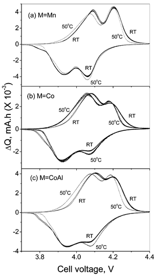 | ||
| Fig. 1 CVs of the Li(M1/6Mn11/6)O4 (M = Mn, Co, CoAl) cells at ambient temperature (27 °C; full line) and at 50 °C (dotted line). Li metal acts as counter and reference electrode and scan rate is 0.052 mV s−1. One or more cycles are shown. | ||
The CV profile at 50 °C does not show any additional peaks, but the anodic peak positions around 4.1 V of the undoped and doped spinels shift slightly to lower voltage and become more prominent as compared to the values at ambient temperature. In addition, for LiMn2O4 there is a decrease in the peak intensity. The anodic peak positions and intensity at ∼4.2 V are unchanged in LiMn2O4, whereas the respective peaks at 50 °C in doped spinels shift slightly to lower values with increased intensity. The cathodic CV peak positions at 50 °C remain unaffected and, in the doped spinels, the peak at 4.07 V becomes more prominent at 50 °C in comparison to that at ambient temperature. Thus the CV profiles at ambient temperature and 50 °C show differences in the intercalation kinetics between M = Mn and M≠Mn spinels. The minor decrease in the anodic peak voltages may be due to the reduction in the cell impedance. Similar shifts in the CV peak positions at 60 and 70 °C as compared to ambient temperature were also observed in pure LiMn2O4 by Ma et al.30 Studies by Yamane et al.31 have shown that the oxidation peak positions of LiMn2O4 have moved to the higher voltage side on storing the cell at 80 °C, indicating difficulty in extracting Li from the compound. The minor shift in the anodic CV (ΔQ/V) profile at 50 °C is also reflected in the voltage vs. capacity profile of the cells recorded at ambient temperature and 50 °C as shown in Fig. 2. The continuous increase in cell voltage in the cell with M ≠ Mn at ambient temperature and 50 °C shows a single phase extraction process, which is in accordance with the suppressed two-phase transition on doping. However, LiMn2O4 at 50 °C shows a slightly higher voltage at the end-of-charge compared to the profile at ambient temperature. This could be due to the presence of degradation products (such as Li2MnO3, λ-MnO2) as observed by others on cycling LiMn2O4 at elevated temperatures7–9,19,31 and which can bring about a change in the equilibrium potential. Further, such a change in voltage profile can also be possible by the conversion of the high voltage, coexisting two-phase region, to a more stable single-phase on cycling the cell at elevated temperatures as reported by Amatucci et al.2 and Xia et al.3 The continuous increase in cell voltage at 50 °C compared to the flat plateau at ambient temperature (more clearly seen in the equilibrium (steady-state) cell voltage (Es) vs. x plot discussed later) on charging LiMn2O4 is also in support to this argument. The formation of such degradation products (Li2MnO3, λ-MnO2) and new phase formation can contribute to the capacity fading in LiMn2O4 due to active material loss and more importantly by affecting the kinetics of Li ion in the electrode. The cycling performance of the compounds Li(M1/6Mn11/6)O4 (M = Mn, Co, CoAl) at 50 °C, shown in Fig. 3 clearly indicate the improved stability for M ≠ Mn up to 80 cycles at 0.5C rate in the voltage window 3.5–4.3 V vs. Li. As expected, the dopant M ions are not electrochemically active in this voltage region and reduce the discharge capacity. Thus the CVs and the voltage vs. capacity profiles at ambient temperature and 50 °C show differences in Li insertion/extraction kinetics for M ≠ Mn spinels, which are reflected in their cycling performance and are brought about by the proposed structural stabilisation.
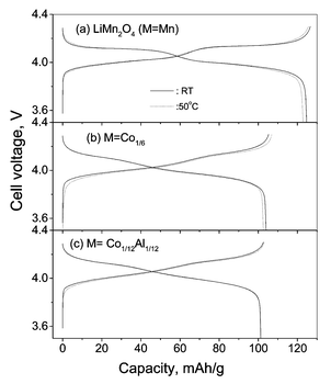 | ||
| Fig. 2 Voltage vs. capacity profiles of the cathodes, Li(M1/6Mn11/6)O4 (M = Mn, Co, CoAl) at ambient temperature and 50 °C at C/10 rate between 3.5 and 4.3 V vs. Li. | ||
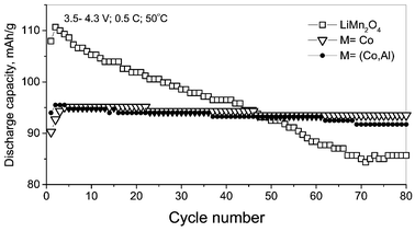 | ||
| Fig. 3 Cycling performance up to 80 cycles of the cathodes, Li(M1/6Mn11/6)O4 (M = Mn, Co, CoAl) at 50 °C at 0.5C rate. | ||
Li+ diffusion coefficient
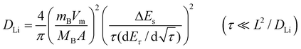
The chemical diffusion coefficient of lithium (DLi) in the cathode materials LixMn2O4 and LixMO2 (M = Co, Ni, Mn) can be determined by a variety of electrochemical techniques such as GITT,32–34 potentiostatic intermittant titration technique (PITT),22,35 slow scan cyclic voltammetry (SSCV)35 and EIS.33,36 The DLi values determined by different techniques show significant discrepancies due to the limitations involved in each measurement. GITT is established to be a reliable technique to determine the DLi with greater accuracy for intercalation compounds of varying composition, x (or voltage).32–34In GITT, the lithiation or delithiation of the host electrode with a known composition (x in LixMyOz) and in thermodynamic equilibrium with Li metal is achieved by applying a constant current flux (I0) for a limited time period τ, at the end of which the compound will have a known Li content, x ± Δx, depending on the direction of the current. As a result of change in x, the equilibrium cell voltage (E0) increases (or decreases according to the direction of the current) with time, and is superimposed on an IR drop due to the current flux through the electrolyte and interface. The total change in cell voltage (ΔEτ) during the current flux can be obtained by subtracting the IR drop. After the current is interrupted at τ, the cell is allowed to relax to its new steady-state potential Es, from which the change in the steady state voltage ΔEs (=Es − E0) over the galvanostatic titration can be determined. The procedure is then repeated until the composition (x) or voltage interval of interest is covered. The DLi in the compound can be determined by using Fick’s second law of diffusion. After a series of assumptions and simplifications, for sufficiently small current flux where ΔEs for a single titration is small, the equation for DLi can be written as:32,33
 | (1) |
 | (2) |
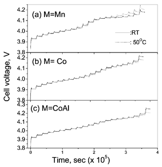
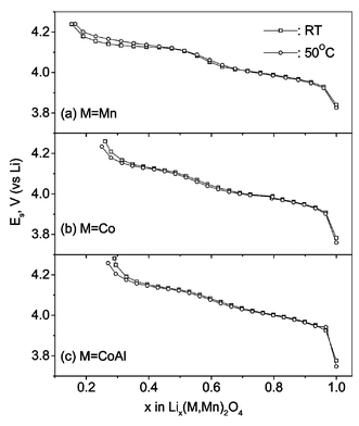
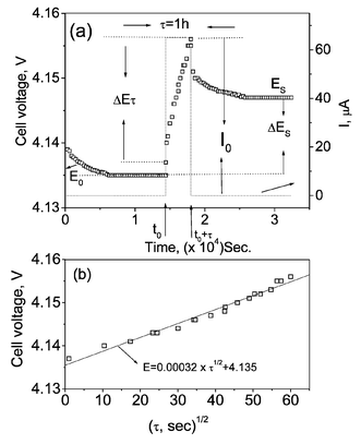
GITT measurements have been performed on Li(M1/6Mn11/6)O4 (M = Mn, Co, CoAl) at ambient temperature and at 50 °C as a function of voltage (and lithium content x) in the range 3.5–4.3 V. Fig. 4 shows the GITT curves (voltage vs. time) for the fifth charge cycle for the cells at ambient temperature and the 7th charge at 50 °C. The cell was first charged at a constant current flux (∼C/20 rate) for an interval of 1 h followed by an open circuit stand for 4 h to allow the cell voltage to relax to its steady-state value (Es). The procedure was repeated for the full voltage window of operation. The steady-state equilibrium voltage (Es) values of the cells at ambient temperature and 50 °C are shown in Fig. 5 against x in Lix(M,Mn)2O4. These are equivalent to open circuit voltage (OCV) at varying x. It is seen that the cell with LixMn2O4 shows higher Es values which varies continuously with x at 50 °C as compared to the values at ambient temperature towards the end-of-charge (x < 0.5). This indicates the conversion of the two-phase region observed at ambient temperature to a single-phase at 50 °C as discussed earlier. For the substituted spinels, the Es values at 50 °C are slightly lower than the ambient temperature values in the full range of voltage. The Esvs. x profiles (Fig. 5) are similar to the voltage vs. capacity profiles (Fig. 2) and the suppression of the two step processes at x ∼ 0.5 with doping is also seen clearly. From the titration curves (Fig. 4), it can be seen that the cell potential stabilises to the Es value well before the onset of next titration. The applied current flux and the resulting voltage profile for a single titration at 4.14 V for the cell with M = Co at ambient temperature is shown in Fig. 6a with schematic labelling of different parameters, ΔEτ, ΔEsetc. The cell voltage during the time period τ on application of I0 at time t0, where the cell voltage is stabilised for the above titration is plotted against √τ which fits into a straight line as shown in Fig. 6b. The values of DLi calculated by substituting the value of slope from Fig. 6b in eqn. (1) and that calculated using eqn. (2) from the titration curve shown in Fig. 6a at 4.14 V are, respectively, 2.99 and 2.89 (±0.05) × 10−10 cm2 s−1. These are in close agreement and thus validates the use of eqn. (2) for the calculation of DLi and the assumptions made in the derivation of eqns. (1) and (2). The Vm values deduced from the crystallographic data are 41.8, 41.3 and 41.2 cm3.mol−1, respectively, for M = Mn, Co and CoAl in Li(M1/6Mn11/6)O4. The DLi calculations above are based on the assumption that the Vm remains unchanged with change in Li content in the compounds. Further, the geometric surface area of the electrode is taken as the total contact area between the electrode and the electrolyte (A). It must be mentioned that the actual surface area of the active material in contact with the electrolyte in composite electrode systems depends on the particle size of the active material and morphology of the electrode and must be larger than the geometric area due to the penetration of electrolyte, and accordingly the DLi values will have some uncertainty. Care has been taken in the present study to minimise the latter by making the composite electrode as thin as possible (20–25 µm) and the identical electrode composition and processing parameters (such as thickness, active material weight, etc.) enables a direct comparison of DLi values for different M-substitution. Further, the materials (especially LiMn2O4) show a two-phase transition as x in Lix(M,Mn)2O4 reaches ∼0.5. Therefore, Li ion diffusion can occur through the phase boundary and also in each phase and hence the measured DLi would be the resultant average value, in the voltage range of the two phase region. Taking these aspects into consideration, the DLi values obtained by eqn. (1) and (2) for all the Li(M,Mn)2O4 are to be treated as the empirical (apparent) rather than the true values.
 | ||
| Fig. 4 GITT curves for the fifth charge cycle for the cells Li/Li(M1/6Mn11/6)O4 (M = Mn, Co, CoAl) at ambient temperature (27 °C; full line) and at 50 °C (7th charge; dotted line) as a function of time. | ||
 | ||
| Fig. 5 The steady-state equilibrium voltage (Es) for the cells at ambient temperature (□) and at 50 °C (○) as a function of x in Lix(M1/6Mn11/6)O4 (M = Mn, Co, CoAl). | ||
 | ||
| Fig. 6 (a) The applied current flux and the resulting voltage profile for a single titration at 4.14 V for the cell with M = Co at ambient temperature with schematic labelling of different parameters. (b) The variation of cell voltage vs. √τ during the time period τ on application of I0 for the above titration (M = Co). | ||
The empirical Li ion diffusion coefficient (DLi) calculated from the GITT curves for the compounds Li(M1/6Mn11/6)O4 (M = Mn, Co, CoAl) as a function of cell voltage at ambient temperature and 50°C are plotted in Fig. 7. The DLi values are in the range 1 × 10⁻⁹–10−10 cm2 s−1 and the values for M = CoAl lie in a narrow range as compared to those with M = Mn and Co. Our DLi values are in good agreement with those reported by Wakihara et al.37 (10−9–10−10 cm2 s−1; 0.2< x <0.85; current pulse relaxation technique) and Zhang et al.38 (9.65 × 10⁻¹⁰–5.78 × 10⁻¹⁰ cm2 s−1; x = 0.3; EIS) for composite LixMn2O4 electrodes and that obtained by Mohamedi et al.39 (5 × 10⁻⁹–1 × 10⁻¹⁰ cm2 s−1; 3.7–4.4 V; EIS) in thin film (1 µm) LiMn2O4. However, our values are slightly higher than those obtained by Aurbach et al.22 (1 × 10⁻¹¹–10−13 cm2 s−1; 3.8–4.3 V; PITT) on composite LiMn2O4 and by Julien et al.40 (6 × 10⁻¹²–1 × 10⁻¹⁰ cm2 s−1; 0.5< x <1.0; GITT) in thin film (300 °C annealed) LixMn2O4. The DLi values of Li(M,Mn)2O4 show a decrease with Li de-intercalation at ambient temperature and 50 °C (Fig. 7). Such a decrease was also observed in thin films of LiMn2O4 by different groups on Li extraction and can be explained as due to the contraction of the crystal lattice on Li removal.40,41 In all the compounds the DLivs. voltage plots show two minima corresponding to the CV peak positions (Figs. 1 and 7). Similar minima in DLivs. voltage plots which coincide with the cyclic voltammogram peak positions were also observed for thin film39,41 as well as in bulk composite electrodes of LiMn2O4.18,22 As observed in the GITT curve (Fig. 4), at the end of charging, the equilibrium potential of LiMn2O4 shifts to higher voltage at 50 °C as compared to the value at ambient temperature. This is also reflected in Fig. 7a as a shift in the second minimum to 4.17 V at 50 °C from 4.13 V at ambient temperature in the DLi values and the profile changes showing a widening of the voltage region for DLi minima (4.10–4.14 V at ambient temperature to 4.09–4.20 V at 50 °C), even though the absolute values remain in the same range at both temperatures of measurement. The DLi values and the positions of the observed minima at ambient temperature and 50 °C coincide very well for all the voltage range for M = Co and CoAl (Fig. 7). It is worth mentioning that the intensity of the minimum in the DLivs. voltage curve decreases in the substituted spinels (M ≠ Mn) compared to the pristine LiMn2O4 indicating that the two-phase transition is suppressed by the substitution, as also observed in the CV and voltage vs. capacity profiles. The almost identical DLi values at ambient temperature and 50 °C for the cells with M ≠ Mn indicate that their Li ion kinetics do not change much with temperature. The fact that DLi values are low in LiMn2O4 in the voltage range 4.12–4.18 V with a more pronounced minimum in this two-phase region, and the shift of equilibrium potential to the higher voltage side at 50 °C as compared to ambient temperature, indicate that the Li ion kinetic (diffusive) limitation in the undoped spinel contributes to capacity fading, especially on charging to 4.3 V.
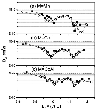 | ||
| Fig. 7 The calculated DLi from the GITT data for the compounds, Li(M1/6Mn11/6)O4 (M = Mn, Co, CoAl) as a function of cell voltage at ambient temperature (■) and at 50 °C (○). | ||
EIS
EIS is a powerful technique to identify the kinetics of Li ions in oxide cathodes.18,22,23,33,36,38–43 The Li intercalation and de-intercalation for these materials are normally modelled as a multi-step process which involves and reflects a series of processes occurring during Li removal and insertion. The measured impedance data are fitted to a proper equivalent circuit consistent with the processes occurring in the electrode envisaged by other physico-electrochemical investigations. An analysis of the impedance response can differentiate the contribution of Li ion migration through the surface film, charge transfer through the electrode/electrolyte interface and the solid state diffusion of Li ions in the cathode.18,22,33Fig. 8a represents the Nyquist plots measured on the freshly fabricated cells for pure and M (M = Co, CoAl)-substituted spinels. The impedance response of the cells after the first charge to 4.3 V (current density =15 mA g−1) is shown in Fig. 8b. These measurements were done at ambient temperature. It is clear that the impedance responses of the cells after the first charge cycle differ from those of the fresh cells. The fresh cells for all M show one semicircle in the high frequency region (lower Z′ values) followed by a Warburg contribution at the low frequency side (higher Z′ values). As can be seen, in the charged cells, the total impedance decreases drastically (by a factor of 3 or 4) and the high frequency side of the spectra has developed into three overlapped semicircles. For the cell with pristine LiMn2O4, the third semicircle at the low frequency side is not well developed whereas for the M = Co and CoAl doped spinels the third semicircle is clearly seen (Fig. 8b). The appearance of the overlapped semicircles is understood by the composite nature of the electrode. The initial current flux facilitates efficient electrolyte penetration into the composite electrode with a better electrode/electrolyte contact. This would lead to changes in the time constants related to the different processes at the interface and the semicircles corresponding to them become somewhat distinguishable. The decrease in impedance of the fresh cell on subjecting it to current flux (first charging) is due to the activation of the electrode surface for more efficient electronic charge transfer. Similar decreases in impedance were also observed in a plastic Li ion cell with LiMn2O442 as well as in the layered oxide cathodes during their initial charge cycles.33 The impedance spectra of Fig. 8 were analysed using physical processes that could be represented by resistive/capacitive combination. The relevant equivalent circuits are shown inset in Fig. 8. The circuit elements were deduced by fitting the experimental data points to the respective equivalent circuit. For the impedance plots in which the low frequency semicircle is absent, the respective circuit elements (R3 and constant phase element (CPE) CPE3; shown inside the dotted rectangle in Fig. 8b) were excluded for the fitting the data with the equivalent circuit. To compensate for the non-homogeneity of the composite electrode (reflected as ‘depressed semicircle’ in the impedance spectra, where the centre of the arc of the semicircle does not touch the Z′-axis), a CPE is used in place of the capacitor to model the data, as shown in Fig. 8. The impedance of the CPE is defined as Z = 1/B(jω)n where j = √(−1), ω is the angular frequency, and B and n are constants. The CPE becomes an ideal capacitor (Ci) when n = 1, and then B = C. In Figs. 8a and b the continuous line represents the fitting as per the equivalent circuit, whereas the symbols denote the experimental data points as a function of frequency.
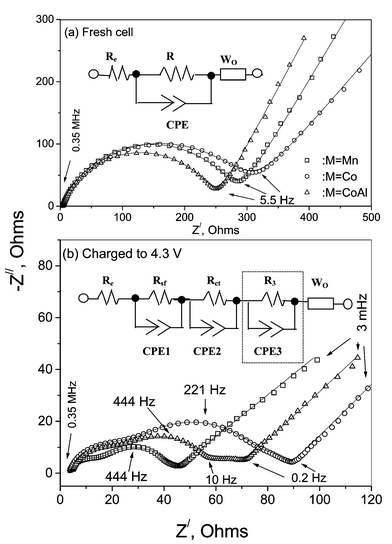 | ||
| Fig. 8 (a) Nyquist plots measured on the freshly fabricated cells for pure and M (M = Co, CoAl) substituted spinels. (b) Nyquist plots of the above cells after the first charge to 4.3 V. Equivalent circuits used for curve fitting are shown inset. Circuit elements inside the dotted rectangle in (b) are those excluded for fitting the data where the low frequency (third) semicircle is absent. Symbols are experimental data and full lines are fitted curves. | ||
The measured impedance response of the cells as a function of cycle number at ambient temperature for the pristine and doped spinels are shown in Fig. 9. For each measurement, the cells were galvanostatically cycled to the desired cycle number followed by charging them to 4.3 V(∼C/5 rate) and left in the open circuit condition for 2 h to relax the cell potential (E) to a stable value. The impedance spectra were then measured with the cells in open circuit. The spectra of all the cells subjected to multiple charge–discharge cycles are qualitatively identical to the ones after their first charge cycle, as is clear from Figs 8b and 9. The impedance spectra of the LiMn2O4 are similar to those observed by others,18,22,38,43 which reflects the Li ion migration through the surface film (high-to-medium frequency semicircle; 0.35 MHz–8 kHz), charge transfer at the interface coupled with the double layer capacitance (medium frequency; 8 kHz–10 Hz) and a Warburg contribution that reflects Li ion migration through the bulk of the material (0.2 Hz–3 mHz). The third semicircle at the low frequency side (10 Hz–0.2 Hz) , which is pronounced only in doped spinels was not, however, seen by others.18,22,43 Fitting the experimental data points with the equivalent circuit (Fig. 8b) gives R3 = 10(±2) Ω for M = CoAl after its first charge. This value reduces to 5(±1) Ω for the second cycle and remains at 2(±1) Ω up to the 80th cycle. For M = Co, R3 = 5(±1) Ω after the first charge. From the second cycle onwards, R3 becomes negligible since the impedance spectra showed only a shoulder (overlapped semicircle) on the low frequency side. The fact that the contribution of R3 is prominent only in the doped spinels leads us to think that it could be due to a surface film formed on the electrode surface in contact with the electrolyte. It must be mentioned at this juncture that Kang and Goodenough4 have speculated the formation of a surface phase on the sol–gel prepared LiMn2O4 and attributed their observed cycling stability in the 3 V range to the surface phase.
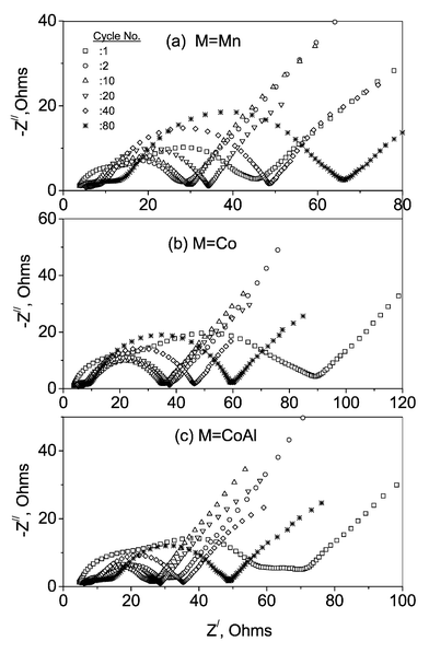 | ||
| Fig. 9 Nyquist plots of the cells as a function of cycle number for the pristine and doped spinels. Measurements were done on charged cells after the respective cycle numbers (indicated). See text. | ||
The circuit elements Rsf, Csf and nCPE1 (surface film resistance, its associated capacitance, and n value for the corresponding CPE, respectively, associated with the high frequency semicircle), Rct, Cdl, and nCPE2 (charge transfer resistance, its associated double layer capacitance, and n value for the CPE, respectively, associated with the medium frequency semicircle) were deduced from Figs. 8b and 9 by fitting the experimental data points to the equivalent circuits. These values as a function of cycle number are shown in Fig. 10. The Rsf and Rct show a sudden decrease during the first few charge cycles (<5) and then gradually increase with cycle number. This can be attributed to the activation of the electrode surface. It is known that the pristine composite electrode is covered with a surface film, possibly Li2CO3, which on contact with the electrolyte can form complex species as described by Aurbach et al.18,22 On starting the charge–discharge cycling, the current flux can destroy or replace the passive surface film covering the electrode by more active ones, reducing the surface film resistance and enabling easy charge transfer at the electrode/electrolyte interface, which can in turn reduce the total cell impedance (Rct and Rsf), as seen from Figs. 9 and 10. Since the charge transfer occurs at the interface, the Li ions have to pass through the surface film and obviously the charge transfer process cannot be treated as independent. The nature of the surface film would also influence the charge transfer processes and a more resistive and thicker surface film would hinder the charge transfer kinetics. Earlier, we have observed a near proportional increase in Rct and Rsf values with cycling in the layered O2-phase compounds, Li(2/3) + x(Ni1/3Mn2/3)O2, x = 0 and 1/333 and have shown that the variation of the surface film and the charge transfer resistances are inter-related. The similar nature of variation of Rct and Rsf on cycling in the present spinels is in accordance with the above observations. After the initial formation cycle, the nature of variation of Rct and Rsf for all the compounds, M = Mn, Co, CoAl are same, with the undoped spinel (M = Mn) showing a slightly faster increase with cycling (Figs. 10a and d). It is known that prolonged cycling and holding the cells at higher potentials lead to the electrolyte dissociation and active material dissolution assisted by structural changes in pristine spinel. The mass deposition of such dissolution products on the electrode surface was observed on repeated cycling.22 The higher rate of increase of Rsf and Rct for undoped spinel indicates a higher rate of surface film formation on the electrode (Figs. 10a and d). This observation is in accordance with that made by others in their impedance studies43 and to the general conclusion that the undoped LiMn2O4 has a higher rate of structural degradation on cycling.5,7–9,17
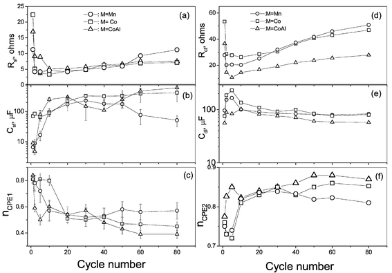 | ||
| Fig. 10 Variation of the circuit elements with cycle number for the Li(M1/6Mn11/6)O4 (M = Mn, Co, CoAl) cells derived from the impedance data. (a), (b) and (c) are, respectively, the Rsf, Csf and the exponent n for the CPE1 element; (d), (e) and (f) are, respectively, the Rct, Cdl and the exponent n for the CPE2 element. Error bars are shown wherever the error estimation is beyond the size of the data points (Fig. 10b and c). | ||
The capacitance associated with the surface film (Csf) shows an increase during the initial cycles (<5), indicating proper electrolyte penetration into the composite electrode. Since the capacitance Ci ∝ A/l, where A is the geometric surface area and l is the thickness of the surface film, proper electrolyte penetration during the formation cycle will increase the A value and hence Csf as observed (Fig. 10b). The Csf values tend to remain stable for M = Co, CoAl, whereas it decreases for M = Mn in the range 30–80 cycles (Fig. 10b). It is reasonable to assume that the geometric surface area of the electrode surface (or the surface film) remains constant after the initial formation cycle. Therefore, the decreasing trend of Csf observed in the undoped spinel is in accordance with the increased rate of surface film formation. Similar enhanced surface film resistance was also noticed by Wang et al.43 on undoped spinel. The corresponding nCPE1 values (associated with Rsf and Csf) show a continuous decrease with cycling except when M = Mn, after 40 cycles. The value of n is a measure of the inhomogeneity of the interface for n < 1.41 The observed low values, 0.5 ± 0.1 for all M after 20 cycles, indicate a highly porous and inhomogeneous nature for the composite electrode surface (Fig. 10c).
The double layer capacitance (Cdl) values are in the range 60–250 µF for all M and agree with the values expected for the charge transfer processes.22,33 The initial increase in Cdl (<5 cycles) can be explained as due to the activation of the electrode surface with an increased rate of charge transfer at the interface leading to a more uniform double layer and the Cdl values stabilise to 100 (±20) µF after 20 cycles (Fig. 10e). The nCPE2 values increase for the initial cycles (<10) and stabilise in the range 0.81–0.87 during 10–80 cycles for M = Co and CoAl whereas a decreasing trend is observed for M = Mn after 30 cycles (Fig. 10f). Thus, the activation of the electrode surface leading to more uniform charge transfer, is also reflected in the n values.
The Rsf and Csf values discussed above show an increased contribution to surface film formation on LiMn2O4 compared to the doped spinels Li(M,Mn)2O4, (M = Co,CoAl) on cycling. This increased rate of surface film formation influences the charge transfer kinetics and would contribute to capacity fading in undoped spinel. In the doped spinels and especially for M = CoAl, the kinetics of Li ion migration at ambient temperature and 50 °C and the impedance response of the cells with cycling show distinguishable changes which can account for the observed reduced capacity fading as compared to the undoped spinel. The present observations are in accordance with the conclusion that proper doping at the Mn site can improve the performance of spinel electrodes.5–17 The low frequency semicircle, which is prominent in the doped spinels in the present study, has a role in delivering stable performance, especially in minimising the material dissolution as speculated by Kang and Goodenough.4
Conclusions
The M-substitution in LiMn2O4 shows improved charge–discharge cycling stability both at ambient temperature and at 50 °C up to 80 cycles at 0.5C rate and was ascribed to structural stabilisation induced by the substitution. CV data at ambient temperature and 50 °C corroborate the above conclusion. The apparent Li diffusion coefficient (DLi) obtained from GITT in the voltage range of operation of the cell (3.5–4.3 V vs. Li) at ambient temperature and 50 °C is in the range 1 × 10⁻⁹–10−10 cm2 s−1 for M = Mn, Co and (Co,Al). The intensity of the minima observed in the DLivs. voltage plots in the vicinity of the CV peak positions are seen to decrease on doping in LiMn2O4, which indicates the suppression of the two-phase formation in the high voltage (4.2 V) region. The impedance spectra at ambient temperature of the compounds up to 80 charge–discharge cycles have been fitted to equivalent circuits. The trends in the variation of the EIS-derived parameters with cycle number and DLivs. voltage profiles in the compounds with M = Co, CoAl as compared to LiMn2O4 lead to the conclusion that the observed cycling stability in the doped spinels originates in the improved Li ion kinetics in addition to the suppression of structural changes and associated material dissolution.References
- M. M. Thackeray, Prog. Solid State Chem., 1997, 25, 1 CrossRef CAS.
- G. G. Amatucci, C. N. Schmutz, A. Blyr, C. Sigala, A. S. Gozdz, D. Larcher and J. M. Tarascon, J. Power Sources, 1997, 69, 11 CrossRef CAS.
- Y. Xia, Y. Zhou and M. Yoshio, J. Electrochem. Soc., 1997, 144, 2593 CAS.
- S.-H. Kang and J. B. Goodenough, J. Electrochem. Soc., 2000, 147, 3621 CrossRef CAS.
- K. M. Shaju, G. V. Subba Rao and B. V. R Chowdari, Solid State Ionics, 2002, 148, 343 Search PubMed.
- D. Kovacheva, H. Gadjov, K. Petrov, S. Mandal, M. G. Lazarraga, L. Pascual, J. M. Amarilla, R. M. Rojas, P. Herrero and J. M. Rojo, J. Mater. Chem., 2002, 12, 1184 RSC.
- M. M. Thackeray, C. S. Johnson, A. J. Kahaian, K. D. Kepler, J. T. Vaughey, Y. Shao-Horn and S. A. Hackney, J. Power Sources, 1999, 81–82, 60 CrossRef CAS.
- G. Amatucci, A. D. Pasquier, A. Blyr, T. Zheng and J.-M. Tarascon, Electrochim. Acta, 1999, 45, 255 CrossRef CAS.
- Y.-S. Lee and M. Yoshio, Electrochem. Solid-State Lett., 2001, 4, A85 CrossRef CAS.
- P. Aitchison, B. Ammundsen, D. J. Jones, G. Burns and J. Roziere, J. Mater. Chem., 1999, 9, 3125 RSC.
- D. Song, H. Ikuta, T. Uchida and M. Wakihara, Solid State Ionics, 1999, 117, 151 Search PubMed.
- L. Guohua, H. Ikuta, T. Uchida and M. Wakihara, J. Electrochem. Soc., 1996, 143, 178.
- G. Pistoia, A. Antonini, R. Rosati, C. Bellitto and G. M. Ingo, Chem. Mater., 1997, 9, 1443 CrossRef CAS.
- Y. Shao-Horn and R. L. Middaugh, Solid State Ionics, 2001, 139, 13 Search PubMed.
- L. Hernan, J. Morales, L. Sanchez, E. R. Castellon and M. A. G. Aranda, J. Mater. Chem., 2002, 12, 734 RSC.
- Y.-K. Sun, C. S. Yoon, C. K. Kim, S. G. Youn, Y.-S. Lee, M. Yoshio and I.-H. Oh, J. Mater. Chem., 2001, 11, 2519 RSC.
- M. C. Tucker, J. A. Reimer and E. J. Cairns, J. Electrochem. Soc., 2002, 149, A574 CrossRef CAS.
- D. Aurbach, M. D. Levi, K. Gamulski, B. Markovsky, G. Salitra, E. Levi, U. Heider, L. Heider and R. Oesten, J. Power Sources, 1999, 81–82, 472 CrossRef CAS.
- T. Aoshima, K. Okahara, C. Kiyohara and K. Shizuka, J. Power Sources, 2001, 97–98, 377 CrossRef CAS.
- J. Cho and M. M. Thackeray, J. Electrochem. Soc., 1999, 146, 3577 CrossRef CAS.
- W. Huang and R. Frech, J. Power Sources, 1999, 81–82, 616 CrossRef CAS.
- D. Aurbach, M. D. Levi, E. Levi, H. Teller, B. Markovsky, G. Salitra, U. Heider and L. Heider, J. Electrochem. Soc., 1998, 145, 3024 CAS.
- F. Orsini, A. D Pasquier, B. Beaudoin, J. M. Tarascon, M. Trentin, N. Lagenhuizen, E. D. Beer and P. Notten, J. Power Sources, 1998, 76, 19 CrossRef CAS.
- R. Premanand, A. Durairajan, B. Haran, R. White and B. Popov, J. Electrochem. Soc., 2002, 149, A54 CrossRef CAS.
- K. M. Shaju, G. V. Subba Rao and B. V. R. Chowdari, Solid State Ionics, in press Search PubMed.
- K. M. Shaju, G. V. Subba Rao and B. V. R. Chowdari, Electrochem. Commun., 2002, 4, 633 CrossRef CAS.
- A. Ott, P. Endres, V. Klein, B. Fuchs, A. Jager, H. A. Mayer, S. Kemmler-Sack, H.-W. Praas, K. Brandt, G. Filoti, V. Kunczer and M. Rosenberg, J. Power Sources, 1998, 72, 1 CrossRef CAS.
- K. Kanamura, H. Naito, T. Yao and Z. Takehara, J. Mater. Chem., 1996, 6, 33 RSC.
- A. Van der Ven, C. Marianetti, D. Morgan and G. Ceder, Solid State Ionics, 2000, 135, 21 Search PubMed.
- S. Ma, H. Noguchi and M. Yoshio, J. Power Sources, 2001, 97–98, 385 CrossRef CAS.
- H. Yamane, T. Inoue, M. Fujita and M. Sano, J. Power Sources, 2001, 99, 60 CrossRef CAS.
- W. Weppner and R. A. Huggins, J. Electrochem. Soc., 1977, 124, 1569 CAS.
- K. M. Shaju, G. V. Subba Rao and B. V. R. Chowdari, J. Electrochem Soc., in press Search PubMed.
- J.-S. Hong and J. R. Selman, J. Electrochem. Soc., 2000, 147, 3190 CrossRef CAS.
- M. D. Levi, G. Salitra, B. Markovsky, H. Teller, D. Aurbach, U. Heider and L. Heider, J. Electrochem. Soc., 1999, 146, 1279 CrossRef CAS.
- C. Ho, I. D. Raistrick and R. A. Huggins, J. Electrochem. Soc., 1980, 127, 343 CAS.
- M. Wakihara, L. Guohua, H. Ikuta and T. Uchida, Solid State Ionics, 1996, 86–88, 907 Search PubMed.
- D. Zhang, B. N. Popov and R. E. White, J. Power Sources, 1998, 76, 81 CrossRef CAS.
- M. Mohamedi, D. Takahashi, T. Itoh, M. Umeda and I. Uchida, J. Electrochem. Soc., 2002, 149, A19 CrossRef CAS.
- C. Julien, E. Haro-Poniatowski, M. A. Camacho-Lopez, L. Escobar-Alarcon and J. Jimenez-Jarquin, Mater. Sci. Eng., B, 2000, 72, 36 Search PubMed.
- K. A. Striebel, E. Sakai and E. J. Cairns, J. Electrochem. Soc., 2002, 149, A61 CrossRef CAS.
- F. Orsini, M. Dolle and J.-M. Tarascon, Solid State Ionics, 2000, 135, 213 Search PubMed.
- G. X. Wang, D. H. Bradhurst, H. K. Liu and S. X. Dou, Solid State Ionics, 1999, 120, 95 Search PubMed.
| This journal is © The Royal Society of Chemistry 2003 |