
 Open Access Article
 This Open Access Article is licensed under a Creative Commons Attribution-Non Commercial 3.0 Unported Licence
Full graphitization of amorphous carbon by microwave heating†
Teawon
Kim
a,
Jaegeun
Lee
b and
Kun-Hong
Lee
*a
aDepartment of Chemical Engineering, Pohang University of Science & Technology, 77 Cheongam-Ro, Nam-Gu, Pohang, Gyeongbuk 790-784, South Korea. E-mail: ce20047@postech.ac.kr
bCarbon Convergence Materials Research Center, Korea Institute of Science and Technology, Eunha-ri San 101, Bongdong-eup, Wanju-gun, Jeollabuk-do 565-905, South Korea
First published on 26th February 2016
Abstract
Natural graphite is labelled as a supply risk material due to rapidly increasing demand and limited reserves. The conventional method for the production of synthetic graphite has relied on the thermal heating at an extremely high temperature, 3000 °C, and long processing time, typically 2 weeks. Here, we report a novel and efficient method of graphitization using microwave heating with metal catalysts. The amorphous carbon powders turned into crystalline graphite in 5 minutes. Ideas for the scale-up of this work were proposed. In addition, numerical analysis revealed that the Maxwell–Wagner–Sillars polarization is inadequate for the mechanism underlying the microwave heating of solid carbon materials.
Introduction
Although academic interests have been moved to novel nano-carbons, graphite still dominates the commercial market by an incomparable scale.2,3 The world production of graphite in 2012 was over a million metric tons.3 Metallic properties (high electric and thermal conductivities) and non-metallic properties (high thermal resistance, inertness, and lubricity) of graphite3,10 make it as an essential material for refractories,14 automobiles,15 lithium-ion batteries,17 fuel cells,18 solar cells,19 nuclear reactors,20 and graphene production.21 Owing to the limited reserve of natural graphite and the ever-increasing demand in energy applications, graphite has been designated as a “supply risk material” by the British Geological Survey22 (graphite is ranked 9th in terms of supply risk, higher than the platinum group elements).Synthetic graphite can fill the gap between supply and demand, but there has been not much research on the process of making synthetic graphite. The common manufacturing process used to synthesize graphite, known as Acheson process,23 relies on thermal heating of amorphous carbon to 3000 °C. Although the energy requirements are enormous, (typical processing time is 2 weeks) the Acheson process remains the major industrial process since its invention in the 1960s.3 Several researches about different way of graphitization like current-induced annealing24 or low-temperature graphitization25 were tried, but full-graphitization of bulk carbon in energy and time efficient method has not been reported. Therefore, a novel and energy-efficient graphitization process is highly desirable.
Electromagnetic waves deliver energy as radiation without being dissipated through heat transfer medium.26 A representative example is the kitchen microwave oven, which can heat food products much faster than thermal heating. Microwave heating has been considered as a candidate for an energy-efficient graphitization method. Several reports have described the heating of carbon materials using microwaves, for example, to regenerate activated carbon,27–32 weld carbon nanotube/polymer composites,33–37 and exfoliate graphite.38–45 Full graphitization by microwave heating, however, has yet to be achieved.7
Besides, the mechanism of microwave heating of solid carbons has not been fully understood. The mechanism underlying microwave heating can vary, depending upon the properties of the energy-absorbing material. Although dielectric relaxation is responsible for heating polar molecules, such as water, a very different heating mechanism functions in electron-rich solids, such as metals (free electrons) or solid carbon materials (π-electrons). It has long been proposed that interfacial polarization, that is, Maxwell–Wagner–Sillars (MWS) polarization, is the main mechanism in operation during the microwave heating of solid carbon materials; however, no in-depth studies have tested the validity of this supposition.46,47
Here, we report a novel method of graphitization using microwave heating with catalyst. Although microwave heating has been reported previously, full graphitization of amorphous carbon powders is achieved for the first time by adding catalyst precursors to the amorphous carbon powders. In addition, the mechanism of microwave heating of solid carbons was investigated. We show that MWS polarization is inappropriate for explaining the heating phenomena observed in solid carbon upon microwave irradiation.
Experimental
Materials
Activated carbon powders (product name: G60, KB) and nickel(II) chloride (98%) were obtained from Sigma-Aldrich, USA. Graphite powder was obtained from Samchun Chemical, Korea. The characteristics of activated carbons used in this work are listed in Table S1 in ESI.† Elemental analysis was performed using varioMICRO CHNS, and other characteristics were obtained from the technical information supplied by Sigma-Aldrich.Microwave graphitization
Microwave graphitization was achieved using the experimental system described in our previous works.48 The system consisted of a magnetron, an isolator, a directional coupler, an auto tuner, a quartz reactor, and gas feeders. Impregnated carbon powders were loaded onto the quartz boat, then placed in the quartz reactor. The temperature was measured using an infrared (IR) thermometer, MR1SC, manufactured by Raytek.Nickel chloride (NiCl2) was impregnated with G60 and KB in ethanol. During the impregnation step, 6 mmol NiCl2 (per g carbon powder) were stirred for 5 or more hours at room temperature until all solvents were evaporated. The sample was subsequently dried at 75 °C for 24 hours.
Next, 1000 W and 1400 W microwave radiation was directed onto the G60 and KB samples, respectively. The reactor was filled with argon gas under normal pressure prior to turning on the microwave generator. The flow rate of the argon gas during microwave irradiation was 100 sccm.
The carbon powder underwent structural changes before and after microwave irradiation, as observed using X-ray diffraction (XRD) methods with a CuKα radiation source, Raman spectroscopy (Horiba Jobin Yvon, LabRam HR) using the 514.5 nm line of an argon ion laser, and by transmission electron microscopy (HR-TEM, JEOL JEM-2200FS with image Cs-corrector).
Thermal graphitization
Thermal graphitization was achieved using lab-scale thermal furnace, Lindberg blue M. The experiment was proceeded at 1000 °C with NiCl2-impregnated KB for varying time. Since the heat up time for reaching 1000 °C is 30 min, total processing time of 5, 10, and 30 min heat treated sample was 35, 40, and 60 min respectively. The carbon powder underwent structural changes before and after microwave irradiation, as observed using X-ray diffraction (XRD) methods with a CuKα radiation source.Dielectric loss factor calculation
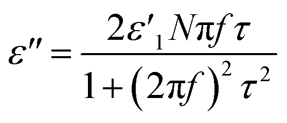
The validity of MWS polarization (also known as interfacial polarization) as a heating mechanism of solid carbons under microwave irradiation was investigated by comparing dielectric loss factor (ε′′).The average power absorbed by the material (Pav) is directly proportional to the effective dielectric loss factor (εeff), as shown in eqn (1), and the effective dielectric loss factor can be separated into the various polarization and conduction components using eqn (2).
| Pav = 2πfε0ε′′effE2rms + 2πfμ0μ′′effH2rms | (1) |
| ε′′eff = ε′′dipolar + ε′′electronic + ε′′atomic + ε′′MWS + ε′′conduction | (2) |
Therefore, the calculated dielectric loss factor based on the MWS polarization theory (ε′′MWS) should have similar value with those of good microwave absorbers if the theory has meaningful impact on the heating of solid carbon under microwave irradiation.
ε′′MWS of solid carbon was calculated using eqn (3) from the original Sillars' paper.13
 | (3) |
 | (4) |
 | (5) |
In the calculation, a composite material that consists of carbons with low electrical conductivity (e.g. diamond and polymer) and carbons with high electrical conductivity (e.g. graphite and graphene) was assumed. Proper value or range of the variables for the material are summarized in Table 1. The calculation was proceeded for much wider range.
| Variable | Proper value/range | The range of calculation |
|---|---|---|
| a Crystallite height (Lc) and the crystallite diameter (La) generally have similar values11 (meaning that n may be varied over a moderate range from 3 to 10 (ref. 13)). | ||
| ε′1 | 1–10 (ref. 5 and 6) | 0–30 |
| ε′2 | 12–15 (ref. 5) | 0–30 |
| σ 2 | 103 to 106 S cm−1 (ref. 8 and 9) | 103 to 106 S cm−1 |
| q | 0–1 | 0–1 |
| n | 3–10a | 3–30 |
| f | 915 MHz, 2.45 GHz | 105 to 1020 Hz |
Results and discussion
Microwave graphitization of activated carbon powders
Full graphitization using microwave heating has not been achieved since the temperature increase reaches saturation below 2000 °C,7,49 far below the graphitization temperature of 3000 °C. In our experiments, amorphous carbon powders were first impregnated with metal catalysts, then they were graphitized using microwave heating (Fig. 1a), being inspired by the fact that precipitation of the graphitic carbon on the metal catalysts occurred at around 1000 °C during thermal heating.50–52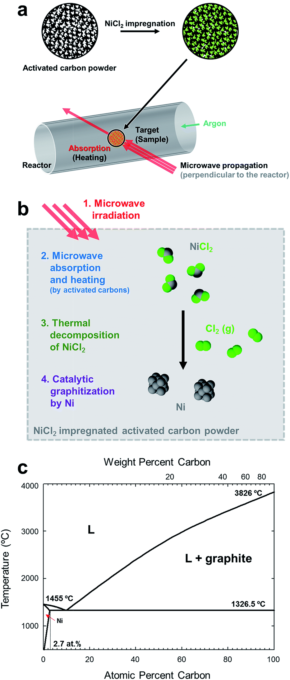 | ||
| Fig. 1 Illustration of microwave graphitization. (a) Experimental procedure. Microwave was irradiated to the activated carbon powders after impregnating nickel chloride. (b) Detail description of microwave graphitization with metal catalyst. Nickel chloride was first decomposed to form nickel catalyst particles, and then amorphous carbon was transformed to graphite with the help of metal catalyst. (c) Nickel–carbon phase diagram.4 Carbide phase in the system is not indicated. | ||
The process of catalytic graphitization is shown in Fig. 1b. First, the energy of irradiated microwave is absorbed by amorphous carbon and the temperature of sample reached over 1000 °C (Fig. S1 and Table S2, ESI†). At such high temperature, NiCl2 and NiCl2·6H2O (Fig. S2, ESI†) undergoes dehydration and decomposition,53 generating nickel particles (Fig. S3 and S4, ESI†). The phase diagram of Ni and C (Fig. 4c) displays that a certain amount of carbon can be dissolved in nickel at high temperature (maximum solubility of carbon in Ni is about 2.7 at% at 1326.5 °C). When the Ni–C solution is supersaturated, the dissolved carbon can be precipitated as a form of graphite spontaneously because the Gibbs free energy change of disordered carbon to graphite is negative.54 The Ni–C solution can reach supersaturation either by (i) additional carbon diffusion into the catalyst or (ii) decrease of solubility by lowered temperature.55 The catalyst particles migrate throughout the carbon matrix and transform relatively disordered carbon into crystalline graphite until they are deactivated. Besides the catalytic graphitization mechanism, it was also suggested that the meta-stable carbide, Ni3C contributes to the precipitation of graphite.4,51,56
The changes in the crystalline structure were confirmed by measuring the XRD patterns (Fig. 2a). The position of the (002) peak in the XRD pattern was directly related to the d-spacing (d002) of the carbon sample.10,57 The changes in the (002) peak were quantified by analyzing a magnified view of the XRD data collected around the (002) peak (full XRD patterns in Fig. S3, ESI†). The value of 2θ obtained at the (002) G60 peak was shifted from 23.45° to 26.50°, and the value of KB was shifted from 24.57° to 26.46° under microwave heating in the presence of the catalysts. The d-spacings of G60 and the value of KB calculated according to Bragg's law were 3.3610 Å and 3.3662 Å, respectively, similar to the d-spacing of the reference graphite powder (3.3612 Å) (detailed information about the d-spacing calculations is provided in Table S3, ESI†). The shapes of the (002) peaks collected from both samples changed dramatically after microwave heating and became nearly identical to the shape obtained from the reference graphite powder. These results indicated that amorphous carbon atoms were effectively graphitized under microwave heating in the presence of the metal catalyst. In the absence of the metal catalyst, however, distinctive changes were not observed in either sample under microwave heating (Fig. S5, ESI†).
 | ||
| Fig. 2 Evolution of the structural ordering during microwave heating. (a) XRD patterns near the (002) peak of graphite, G60 and KB before and after microwave heating. The position and shape of the (002) peaks of G60 and KB nearly coincided with the peak of the reference graphite powder after microwave heating. (b) Raman spectra of G60 and KB before and after microwave heating. The IG/ID ratios of G60 and KB increased to 3.29 and 3.26 respectively, values that were nearly indistinguishable from those obtained from the reference graphite powder. (c–h) TEM image and FFT image (inset) of pristine G60 (c), after microwave heating without catalyst (d) and after microwave heating with catalyst (e). TEM image and FFT image (inset) of pristine KB (f), after microwave heating without catalyst (g) and after microwave heating with catalyst (h). | ||
The Raman spectra (Fig. 2b) further supported the conclusions obtained from the XRD study. Perfect graphite was characterized by a single high-frequency band at 1582 cm−1, which corresponded to the E2g2 mode, or G-band. Disordered carbon was characterized by another broad band at approximately 1350 cm−1, which corresponded to the D-band.58 The ratio of the integrated or maximum intensity of the G-band to the D-band is commonly used to characterize the different types of carbon-based materials.59,60 Higher fractions of the graphitic region produced larger IG/ID ratios. The IG/ID ratios of the pristine samples were 0.92 (G60) and 1.54 (KB), and these values increased to 3.29 (G60) and 3.26 (KB) after microwave heating in the presence of the catalysts. These values were similar to the value obtained from the reference graphite powder (3.34), further supporting the conclusion that the amorphous carbon powders were indeed transformed into graphitic carbon under microwave heating in the presence of the catalysts.
Transmission electron microscopy (TEM) images reconfirmed the transformation from an amorphous structure to a graphitic structure (Fig. 2c–h). Prior to microwave heating, G60 and KB only exhibited disordered microstructures typical of amorphous carbon. The fast Fourier transform (FFT) images showed hollow circles. On the other hand, completely different TEM and FFT images were obtained after microwave heating in the presence of the catalysts. The crystalline ordering was apparent throughout the entire sample, and hexagonal patterns appeared. Multiple sets of dots with six-fold symmetry were observed in the FFT images. These results indicated that multi-layer graphene sheets developed during microwave heating in the presence of the catalysts.
Comparison with thermal graphitization
Interlayer spacing of various carbon materials as a function of the processing temperature is summarized in Fig. 3a. The interlayer spacing, or d-spacing, refer to the distance between adjacent graphene layers. This parameter corresponds to the degree of graphitization.11 In general, the d-spacing of a carbon material tends to decrease as the processing temperature increases during thermal heating (blue symbols). Microwave heating can decrease the d-spacing more efficiently than thermal heating at the same processing temperature, although the lowest achievable value is only 3.42 Å without the help of a catalyst (orange shade). This d-spacing is equivalent to that obtained under thermal heating at 2000 °C (Table S4, ESI†). In the presence of the metal catalyst, however, full graphitization of the carbon powders was achieved with a d-spacing of 3.3610 Å (red symbols, this work).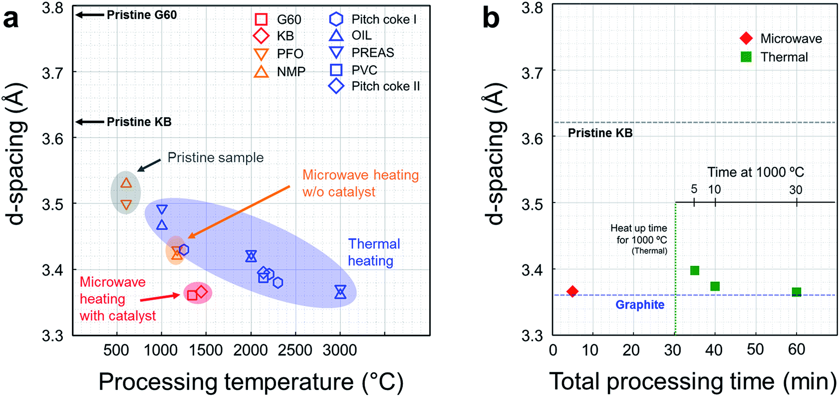 | ||
| Fig. 3 Comparison between microwave graphitization and thermal graphitization. (a) d-Spacing in various carbons as a function of the processing temperature (G60 and KB: activated carbon powders, PFO: pyrolyzed isotropic pitch from fuel oil,7 NMP: naphthalene-derived mesophase pitch.7 Pitch coke I: carbonized coal-tar pitch,12 OIL: cyclohexane soluble fraction of benzene soluble part of coal liquid pitch,11 PREAS: vacuum dried pre-asphaltenes of the benzene-insoluble part of the coal liquid pitch,11 PVC: polyvinyl chloride,16 pitch coke II: carbonized pitch16). Conventional graphitization using resistive heating requires high temperatures exceeding 3000 and extremely long processing times (1–25 h, see the ESI, Table S2†). In the absence of a catalyst, microwave heating changed the crystallinity of the carbon powders over a short period of time; however, full graphitization was not achieved (orange shade). In this work, effective and efficient graphitization was achieved using microwave heating and catalyst precursor. The d-spacing in the activated carbon samples changed to 3.36 Å within 5 minutes of processing time (red symbols). (b) Comparison with thermal catalytic graphitization using lab-scale thermal furnace. Thermal graphitization proceeded for 5, 10, and 30 min at 1000 °C, and microwave graphitization proceeded for 5 min at a 1400 W microwave power. The d-spacing of the raw material (KB) and graphite are presented for reference purposes. | ||
The merits of the microwave graphitization in terms of time required to reach completion were examined by comparing the microwave process conditions to the thermal heating conditions, applied to a NiCl2-impregnated KB sample for different heat treatment periods (Fig. 3b). Microwave graphitization displayed tremendous advantages in terms of the time required to complete the process. Only 5 min of microwave irradiation provided similar structural changes as 60 min of the conventional process (thermal graphitization). Thermal graphitization requires 30 min for heat up to 1000 °C, so additional 30 min is required for the graphitization, whereas heat up over 1000 °C and graphitization was achieved in 230 s and 70 s respectively (Fig S1 and Table S5, ESI†).
We demonstrated the efficiency of microwave heating over conventional heating in graphitization at the lab-scale experiments. The scale-up of our experiment can be done based on the understanding of penetration depth. The definition of penetration depth (dp) is the distance from the surface to a certain point where magnitude of field strength decreases to 1/e of original magnitude at the surface.61 The penetration depth of electric field is expressed as the following equation.
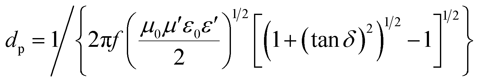
![[thin space (1/6-em)]](https://www.rsc.org/images/entities/char_2009.gif) δ refers to the loss tangent.62
δ refers to the loss tangent.62
The importance of penetration depth in scale-up of microwave reactor is represented in Fig. 4a. Heat is generated from the whole volume of target material when the microwave penetration depth is bigger than the scale of target material (ltarget). When the scale of target material is much bigger than the microwave penetration depth, however, heat is hardly generated from the inside of the material. Only surface region is heated by microwave radiation and the rest of the material is heated by conduction from the surface.
 | ||
| Fig. 4 Scale-up of microwave reactor. (a) The effect of penetration depth on microwave heating. (b) Illustration of conveyor belt type reactor with microwave irradiator. | ||
Crystalline carbon materials have very short penetration depth, typically several microns,47 so most benefits of microwave heating vanish with bulky target material. Nevertheless, if we have an accurate understanding of the penetration depth, scale-up of microwave reactor which still has the advantages of microwave heating is possible. A hint for the scale-up of microwave reactor can be obtained from the plate-type reactor which is commercially available (Fig. S7, ESI†). This reactor was introduced to maximize the heat delivery from the heating fluid to the reactants. A similar approach can be applied to the scale-up of a microwave reactor.
An easy solution to the problem of short penetration depth is the use of conveyer belt type reactor with small size carbon powders (Fig. 4b). A tumbling-bed reactor or a fluidized-bed reactor can also be used because each carbon powder is separated from others. This kind of reactor design enables high productivity, and prevents the problem of short penetration depth at the same time.
Verification of heating mechanism
In spite of the effectiveness and efficiency of microwave heating of solid carbons shown in this work, the study about the heating mechanism is still much to be required. Until now, the mechanisms underlying microwave heating of solid carbons are understood as Maxwell–Wagner–Sillars (MWS) polarization46,63,64 or joule heating reference. However, there has been no in-depth study about the validity of the MWS mechanism. Therefore, we investigated the influence of MWS polarization over microwave heating of solid carbons by dielectric loss factor (ε′′) calculation. As explained in the experimental part, the average power absorbed by the material under electromagnetic wave is directly proportional to the effective dielectric loss factor (ε′′eff) of the material, and ε′′eff consists of various polarizations and conduction components. Therefore, if MWS polarization is responsible for the microwave heating of solid carbons, the calculated dielectric loss factor based on MWS polarization theory should have similar or larger value than the dielectric loss factor of good microwave absorbers, because solid carbons show extreme heating phenomena under microwave irradiation.Among the six variables in the eqn (3) which was used in the dielectric loss factor calculation, n and q only change the numerical value, and do not change the tendency. The dielectric loss factor increases as either n or q increases (Fig. S8–S10†). Thus, in the result part, the influence of the other four variables on the dielectric loss factor was examined. Then, the maximum value in the range of the properties of solid carbons was obtained and compared with the values of other materials for judging whether the MWS polarization is proper or not for the microwave heating mechanism of solid carbons.
At first, the dielectric loss factor (ε′′MWS) was calculated by varying the dielectric constant of solid carbons (ε′1 and ε′2). The dielectric constant of conducting region (ε′1) has little effect on ε′′MWS, and ε′′MWS increases with increasing dielectric loss factor of insulating region (ε′2) as shown in Fig. 5a. The maximum value of ε′′MWS was 1.1 when ε′1 = 30, σ2 = 1000 S cm−1, q = 1, n = 30 and f = 2.45 GHz. The maximum value of calculated dielectric loss factor is 1–2 orders smaller than those of the materials known as good microwave absorbers, even though the range of calculation was much wider. It means that the contribution of MWS polarization is very small for the microwave heating of solid carbons.
 | ||
| Fig. 5 The influence of dielectric constants (ε′1 and ε′1) on the dielectric loss factor of solid carbon based on MWS polarization (ε′′MWS). (σ2 = 1000 S cm−1, q = 1, and n = 30 and f = 2.45 GHz). | ||
Next, the influence of conductivity of conducting region (σ2) and the applied frequency (f) was investigated. A bell-shaped curve was obtained when ε′′MWS was plotted as a function of log frequency (logf) (Fig. 5b). The peak frequency (fpeak) increased as the electrical conductivity of conducting region (σ2) increased. The key results are summarized in Table 2. When σ2 = 103 S cm−1 (around the electrical conductivity of graphite58), fpeak was 2 THz, and the dielectric loss factor at 915 MHz and 2.45 GHz was 0.4117 and 1.1025 respectively. When σ2 = 106 S cm−1 (a much larger value than those of conducting solid carbons8,9), fpeak was 2 PHz, and the dielectric loss factor at 915 MHz and 2.45 GHz was 0.0004 and 0.0011 respectively. In other words, fpeak of solid carbon material is present at a much higher frequency than microwave frequencies. Moreover, ε′′MWS is very small at 915 MHz and 2.45 GHz, typical frequencies in microwave heating. The results indicate that the contribution of MWS polarization to the heating of solid carbons in the range of microwave frequencies is very small or almost negligible.
| σ 2 (S cm−1) | f peak | ε′′915 MHz | ε′′2.45 GHz |
|---|---|---|---|
| 103 | 2 × 10¹² Hz (2 THz) | 0.4117 | 1.1025 |
| 106 | 2 × 10¹⁵ Hz (2 PHz) | 0.0004 | 0.0011 |
Finally, the maximum value of calculated dielectric loss factor based on MWS polarization in the proper range for solid carbons was compared to the value of other materials. As discussed above, ε′′MWS has larger value when ε′1, q, and n become larger, and σ2 becomes smaller. The maximum values within the proper range shown in Table 1 are plotted in Fig. 6 with the dielectric loss factor of other materials. The maximum value of calculated dielectric loss factor for solid carbons based on MWS polarization was 0.0114 under 915 MHz and 0.0306 under 2.45 GHz. These values are far below than the values of the materials known as good microwave absorbers (water + 0.5 M NaCl: 269, methyl alcohol: 15). Actually, they are similar to the values of poor microwave absorbers (alumina: 0.009, mullite: 0.0098). Therefore, it seems inadequate to explain the extreme heating phenomena of solid carbons under microwave irradiation relying only on MWS polarization.
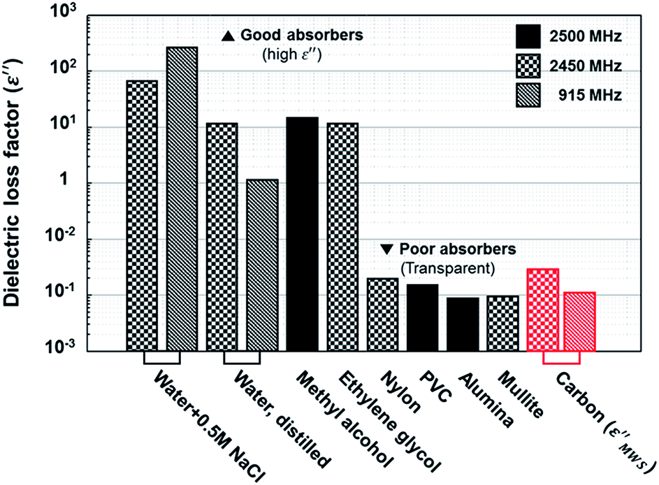 | ||
| Fig. 6 Dielectric loss factor comparison.1 Calculated dielectric loss factors of solid carbon based on MWS polarization (ε′′MWS) are located at poor absorber region, where microwave transparent materials are exist. | ||
Conclusions
In conclusion, we report the full graphitization of amorphous carbon powders by modified microwave heating with the help of a metal catalyst. Because microwave graphitization is much more efficient, in terms of energy and time requirements, than the industrial graphitization method currently in use, this method is expected to provide an alternative approach to producing graphite, which is considered to have a high supply risk. Because the economic gains of our method are considerable, this approach has the potential to revolutionize the graphite industry. We also examined the validity of the Maxwell–Wagner–Sillars polarization, which has long been accepted as a mechanism underlying microwave heating in solid carbons. The dielectric loss factor calculations over a wide range of parameter space revealed that the MWS polarization is certainly inadequate for describing the microwave heating mechanism in solid carbons.Acknowledgements
The present work was supported by Korea Science and Engineering Foundation (KOSEF) grant funded by the Korean government (MEST) (Grant No. 2015-021048). We also acknowledge the Research Institute of Industrial Science & Technology for financial support. This work was also supported by NRF (National Research Foundation of Korea) Grant funded by the Korean Government (NRF-2011-Global Ph.D. Fellowship Program).Notes and references
- M. Gupta and E. W. W. Leong, Microwaves and Metals, Jonh Wiley & Sons(Asia) Pte Ltd, Singapore, 2007 Search PubMed.
- A. Zurutuza and C. Marinelli, Nat. Nanotechnol., 2014, 9, 730–734 CrossRef CAS PubMed.
- Graphite, http://minerals.usgs.gov/minerals/pubs/commodity/graphite/myb1-2013-graph.pdf, (accessed 23.10.2015).
- M. Singleton and P. Nash, J. Phase Equilib., 1989, 10, 121–126 CAS.
- Dielectric Constant Values, http://www.clippercontrols.com/pages/Dielectric-Constant-Values.html#D, (accessed 22.05.2015, 2015).
- Z. Ahmad, Polymer Dielectric Materials, InTech, 2012 Search PubMed.
- K. S. Yang, Y. J. Yoon, M. S. Lee, W. J. Lee and J. H. Kim, Carbon, 2002, 40, 897–903 CrossRef CAS.
- H. O. Pierson, Handbook of carbon, graphite, diamond, and fullerenes: properties, processing, and applications, Noyes Publications, Park Ridge, N.J., U.S.A., 1993 Search PubMed.
- J.-H. Chen, C. Jang, S. Xiao, M. Ishigami and M. S. Fuhrer, Nat. Nanotechnol., 2008, 3, 206–209 CrossRef CAS PubMed.
- K. Kinoshita, Carbon: electrochemical and physicochemical properties, John Wiley & Sons, Inc., Canada, 1988 Search PubMed.
- U. Świetlik, S. Jasieńko and A. Wolski, Carbon, 1993, 31, 461–466 CrossRef.
- K. Kawamura and R. Bragg, Carbon, 1986, 24, 301–309 CrossRef CAS.
- R. W. Sillars, J. Inst. Electr. Eng., 1937, 80, 378–394 Search PubMed.
- W. E. Lee and R. E. Moore, J. Am. Ceram. Soc., 1998, 81, 1385–1410 CrossRef CAS.
- B. Gerard, Surf. Coat. Technol., 2006, 201, 2028–2031 CrossRef CAS.
- R. E. Franklin, Acta Crystallogr., 1951, 4, 253–261 CrossRef CAS.
- M. Armand and J. M. Tarascon, Nature, 2008, 451, 652–657 CrossRef CAS PubMed.
- B. C. H. Steele and A. Heinzel, Nature, 2001, 414, 345–352 CrossRef CAS PubMed.
- K. Imoto, K. Takahashi, T. Yamaguchi, T. Komura, J.-i. Nakamura and K. Murata, Sol. Energy Mater. Sol. Cells, 2003, 79, 459–469 CrossRef CAS.
- D. Butler, Nature, 2004, 429, 238–240 CrossRef CAS PubMed.
- Y. Hernandez, V. Nicolosi, M. Lotya, F. M. Blighe, Z. Y. Sun, S. De, I. T. McGovern, B. Holland, M. Byrne, Y. K. Gun'ko, J. J. Boland, P. Niraj, G. Duesberg, S. Krishnamurthy, R. Goodhue, J. Hutchison, V. Scardaci, A. C. Ferrari and J. N. Coleman, Nat. Nanotechnol., 2008, 3, 563–568 CrossRef CAS PubMed.
- Risk List 2012, https://www.bgs.ac.uk/mineralsuk/statistics/riskList.html, (accessed 15.05.2015).
- Kirk-Othmer concise encyclopedia of chemical technology, Wiley-Interscience, Hoboken, N.J., 5th edn., 2007 Search PubMed.
- A. Barreiro, F. Borrnert, S. M. Avdoshenko, B. Rellinghaus, G. Cuniberti, M. H. Rummeli and L. M. K. Vandersypen, Sci. Rep., 2013, 3, 1115 Search PubMed.
- K. Barbera, L. Frusteri, G. Italiano, L. Spadaro, F. Frusteri, S. Perathoner and G. Centi, Chin. J. Catal., 2014, 35, 869–876 CrossRef CAS.
- A. C. Metaxas and R. J. Meredith, Industrial microwave heating, P. peregrinus on behalf of the Institution of Electrical Engineers, London, UK, 1983 Search PubMed.
- C. Y. Cha and Y. G. Kong, Carbon, 1995, 33, 1141–1146 CrossRef CAS.
- Y. Kong and C. Y. Cha, Carbon, 1996, 34, 1035–1040 CrossRef CAS.
- J. A. Menendez, E. M. Menendez, A. Garcia, J. B. Parra and J. J. Pis, J. Microwave Power, 1999, 34, 137–143 Search PubMed.
- J. A. Menendez, E. M. Menendez, M. J. Iglesias, A. Garcia and J. J. Pis, Carbon, 1999, 37, 1115–1121 CrossRef CAS.
- X. T. Liu, X. Quan, L. L. Bo, S. Chen and Y. Z. Zhao, Carbon, 2004, 42, 415–422 CrossRef CAS.
- C. O. Ania, J. A. Menendez, J. B. Parra and J. J. Pis, Carbon, 2004, 42, 1383–1387 CrossRef CAS.
- M. Zhang, S. L. Fang, A. A. Zakhidov, S. B. Lee, A. E. Aliev, C. D. Williams, K. R. Atkinson and R. H. Baughman, Science, 2005, 309, 1215–1219 CrossRef CAS PubMed.
- C. Y. Wang, T. G. Chen, S. C. Chang, S. Y. Cheng and T. S. Chin, Adv. Funct. Mater., 2007, 17, 1979–1983 CrossRef CAS.
- H. C. Shim, Y. K. Kwak, C. S. Han and S. Kim, Scr. Mater., 2009, 61, 32–35 CrossRef CAS.
- H. Wang, J. Y. Feng, X. J. Hu and K. M. Ng, Nanotechnology, 2009, 20, 095601 CrossRef PubMed.
- R. Xie, J. Wang, Y. Yang, K. Jiang, Q. Li and S. Fan, Compos. Sci. Technol., 2011, 72, 85–90 CrossRef CAS.
- V. Sridhar, J. H. Jeon and I. K. Oh, Carbon, 2010, 48, 2953–2957 CrossRef CAS.
- O. Y. Kwon, S. W. Choi, K. W. Park and Y. B. Kwon, J. Ind. Eng. Chem., 2003, 9, 743–747 CAS.
- L. M. Viculis, J. J. Mack, O. M. Mayer, H. T. Hahn and R. B. Kaner, J. Mater. Chem., 2005, 15, 974–978 RSC.
- B. Tryba, A. W. Morawski and M. Inagaki, Carbon, 2005, 43, 2417–2419 CrossRef CAS.
- E. H. L. Falcao, R. G. Blair, J. J. Mack, L. M. Viculis, C. W. Kwon, M. Bendikov, R. B. Kaner, B. S. Dunn and F. Wudl, Carbon, 2007, 45, 1367–1369 CrossRef CAS.
- G. Q. Xin, W. Hwang, N. Kim, S. M. Cho and H. Chae, Nanotechnology, 2010, 21, 405201 CrossRef PubMed.
- Y. Geng, Q. B. Zheng and J. K. Kim, J. Nanosci. Nanotechnol., 2011, 11, 1084–1091 CrossRef CAS PubMed.
- C. Xiu-Yun, Int. Nano Lett., 2013, 3, 1–5 CrossRef.
- J. A. Menendez, A. Arenillas, B. Fidalgo, Y. Fernandez, L. Zubizarreta, E. G. Calvo and J. M. Bermudez, Fuel Process. Technol., 2010, 91, 1–8 CrossRef CAS.
- T. Kim, J. Lee and K. H. Lee, Carbon letters, 2014, 15, 15–24 CrossRef.
- D. M. Yoon, B. J. Yoon, K. H. Lee, H. S. Kim and C. G. Park, Carbon, 2006, 44, 1339–1343 CrossRef CAS.
- P. J. M. Carrott, J. M. V. Nabais, M. M. L. R. Carrott and J. A. Menendez, Microporous Mesoporous Mater., 2001, 47, 243–252 CrossRef CAS.
- A. Oya and S. Otani, Carbon, 1979, 17, 131–137 CrossRef CAS.
- A. Oya, J. Mater. Sci., 1982, 17, 309–322 CrossRef CAS.
- M. Sevilla and A. B. Fuertes, Carbon, 2006, 44, 468–474 CrossRef CAS.
- S. K. Mishra and S. B. Kanungo, J. Therm. Anal., 1992, 38, 2417–2436 CrossRef CAS.
- E. Fitzer and B. Kegel, Carbon, 1968, 6, 433–446 CrossRef CAS.
- J. Lander, H. Kern and A. Beach, J. Appl. Phys., 1952, 23, 1305–1309 CrossRef CAS.
- C. Mattevi, H. Kim and M. Chhowalla, J. Mater. Chem., 2011, 21, 3324–3334 RSC.
- Y. Hishiyama, M. Inagaki and S. Kimura, Carbon, 1974, 12, 249–258 CrossRef CAS.
- F. Tuinstra and J. L. Koenig, J. Chem. Phys., 1970, 53, 1126–1130 CrossRef CAS.
- D. S. Knight and W. B. White, J. Mater. Res., 1988, 4, 385–393 CrossRef.
- M. S. Dresselhaus and G. Dresselhaus, Adv. Phys., 1981, 30, 139–326 CrossRef CAS.
- A. C. Metaxas, Foundations of Electroheat: A Unified Approach, John Wiley & Sons, Chichester, 1996 Search PubMed.
- M. Gupta and W. L. Wong, Microwaves and metals, John Wiley & Sons, Singapore, Hoboken, NJ, 2007 Search PubMed.
- E. A. Dawson, G. M. B. Parkes, P. A. Barnes, G. Bond and R. Mao, Carbon, 2008, 46, 220–228 CrossRef CAS.
- J. M. V. Nabais, P. J. M. Carrott, M. M. L. R. Carrott, A. M. Padre-Eterno, J. A. Menendez, A. Dominguez and A. L. Ortiz, Carbon, 2006, 44, 1158–1165 CrossRef CAS.
Footnote |
| † Electronic supplementary information (ESI) available. See DOI: 10.1039/c6ra01989g |
| This journal is © The Royal Society of Chemistry 2016 |