
 Open Access Article
 This Open Access Article is licensed under a
 Creative Commons Attribution 3.0 Unported Licence
Diffusion of molecules in the bulk of a low density amorphous ice from molecular dynamics simulations†
P.
Ghesquière
a,
T.
Mineva
b,
D.
Talbi
*a,
P.
Theulé
c,
J. A.
Noble‡
c and
T.
Chiavassa
c
aLaboratoire Univers et Particules de Montpellier UMR 5299, CNRS et Université de Montpellier, Place Eugène Bataillon, 34095, Montpellier Cedex 05, France. E-mail: dahbia.talbi@univ-montp2.fr
bInstitut Charles Gerhardt, UMR 5253 CNRS/ENSCM/UM2/UM1, 8 rue de l’Ecole Normale, 34296 Montpellier Cedex 05, France
cAix-Marseille Univ., CNRS, PIIM UMR 7345, Marseille, 13397, France
First published on 30th March 2015
Abstract
The diffusion of molecules in interstellar ice is a fundamental phenomenon to take into account while studying the formation of complex molecules in this ice. This work presents a theoretical study on the diffusion of H2O, NH3, CO2, CO, and H2CO in the bulk of a low density amorphous (LDA) ice, while taking into account the physical conditions prevailing in space, i.e. temperatures below 150 K and extremely low pressure. This study was undertaken by means of molecular dynamics simulations. For CO2 for which no experimental data were available we conducted our own experiments. From our calculations we show that, at low temperatures, the diffusion of molecules in the bulk of a LDA ice is driven by the self-diffusion of water molecules in the ice. With this study we demonstrate that molecular dynamics allows the calculation of diffusion coefficients for small molecules in LDA ice that are convincingly comparable to experimentally measured diffusion coefficients. We also provide diffusion coefficients for a series of molecules of astrochemical interest.
I Introduction
Astrophysical observations of cold interstellar clouds, comets and icy planetary bodies have revealed the existence of ices mainly composed of water but also containing a few simple molecular species like CO2, CO, NH3, and CH4.1,2 These ices form during the collapse of dense regions within interstellar clouds.3,4 During this process, the density increases while the temperature decreases, allowing the condensation or formation of simple molecules on the dust grains present in these dense regions, also called star-forming regions. It is believed that later in the life of these regions of star formation, when the ices are warmed up until sublimation, these ices could catalyze the formation of complex organic molecules (COMs).5,6 However, even at these temperatures, the scarcity of the molecules present in the ices and the resulting need for the reactants to diffuse and meet each other strongly limit ice chemistry. Whether or not long interstellar time scales can counterbalance the diffusion-limited solid-state reactivity in the diffusion-reaction equation derivation depends on both the reaction rate constants and the reactants diffusion coefficients. Diffusion of molecules in ices is therefore a key phenomenon to take into account when studying the formation of complex molecules in interstellar ices.Diffusion-limited reactivity is also encountered in terrestrial ices, such as polar ice or atmospheric ice,7,8 and drives the capacity of ice particles to modify atmospheric chemistry. An experimental study9 devoted to the structure of interstellar ices showed that at very low temperature (T = 10 K) the condensation phase leads to the formation of a high density porous amorphous ice, which transforms into a low density amorphous (LDA) ice when the temperature increases (from 20 K to 120 K).10 Molecular dynamics (MD) simulations have been applied to understand the evolution of a LDA ice to a high-density amorphous ice11,12 while considering temperature and pressure effects or to study the high-density amorphous ice/crystalline ice Ih compression–decompression at a fixed low temperature.13 Diffusion of small molecules, in crystalline ice,14–18 clathrates18,19 and hydrates,20 has also been studied with molecular dynamics. The previously established interstitial mechanism for He atoms in ice Ih16 has been found inappropriate for the N2 molecules.17 From the comparison of diffusion coefficients of N2, O2, CO2, and CH4 in hexagonal ices Ih14 the bond-breaking diffusion mechanism has been suggested with diffusion velocity being several orders of magnitude larger than that found in the case of an interstitial mechanism. In the interstitial mechanism He atoms have been found to migrate from a stable interstitial site to an adjacent site without a distortion of the lattice. In the bond-breaking mechanism, the hydrogen bonds in the lattice are broken and the molecule jumps between stable sites. The bond-breaking mechanism has also been proposed for the diffusion of formaldehyde in hexagonal Ih ice.15 The most recent work on CO2 diffusion in clathrates has revealed that CO2 diffusion is possible in these solids if water vacancy exists.18 Diffusion has also been quantified in structure materials like H2, tetrahydrofuran clathrate hydrates19 or for water in cyclodextrin hydrates.20 For a more complete insight into molecular diffusion in clathrates we recommend the very recent review by English and MacElroy21 on molecular simulation of clathrate hydrates. All the studies cited above have demonstrated the applicability of several different effective potentials such as TIP4P,22 TIP4P-ice,23 SPC,24 MCY,25 ST2,26 SPC/E,27 and Kawamura potential model to describe various types of ices and to study ice phase changes as well as the diffusivity of molecules in them. A fully atomistic, off-lattice kinetic Monte Carlo technique was applied to compute the diffusion to desorption barrier ratios of CO and CO2 at crystalline ice surfaces at temperatures equal to 25 and 70 K.28 The CO mobility, studied by the same technique, has been reported to be very sensitive to the amorphous ice surface morphology, with the CO molecules trapped by surface nanopores for low CO coverage.29
To the best of our knowledge, diffusivity of molecules in the bulk of LDA ices has not been considered by means of molecular dynamics. The present work aims at bringing additional knowledge on diffusion by studying theoretically the bulk diffusion of H2O, NH3, CO2, CO, and H2CO in a LDA ice as a relevant model for an interstellar ice, at very low temperatures and no pressure.
Experimental studies of bulk diffusion in LDA ices are scarce too.30,31 For these ices, we are only aware of the self-diffusion study of H2O32 in an amorphous water ice near 150 K and of the diffusion of CO, NH3, HNCO and H2CO for temperatures below 140 K33 in a compact amorphous water ice. Based on the results of Collings et al.,34 molecules can be separated into three categories: CO-like molecules, H2O-like molecules and intermediate molecules. According to this earlier work, CO2 is an intermediate molecule, for which such an experimental diffusion study is not available. We have conducted diffusion experiments on CO2 in ice applying the methodology of Mispelaer et al.33 to allow for the comparison of our calculated bulk diffusivity with experimental data for all the studied molecules, i.e. H2O, NH3, CO2, CO, and H2CO.
This paper is organized as follows. First the computational approach and protocols of the MD simulations are detailed (Section II). The experimental set-up for the CO2 bulk diffusion measurements is presented (Section III). Then the computational results are discussed with respect to available experimental data from the literature and from our own experiments (Section IV).
II Computational approach
II-1 The molecular dynamics protocol
In order to investigate the diffusion of small molecules in a low density amorphous ice mimicking an interstellar ice, classical molecular dynamics (MD) simulations using the OPLS–AA (optimized potentials for liquid simulations – all atom)35–37 force field were performed. The σ and ε parameters of the Lennard-Jones (LJ) potential, implemented in the OPLS–AA force field, are summarized in Table 1. The geometrical parameters of the molecules are reported in Table 2. It is worth noting that for a correct description of the charges in the carbon monoxide, a dummy atom D was introduced between C and O, bearing a positive charge in order to account for the nucleophilic character of both C and O atoms.38 The water molecules of the ice were described by the four point rigid TIP4P model22,39 (transferable intermolecular potential four points) with the water molecules described by three sites corresponding to the atoms and an atom M located on the bisector of the HOH angle bearing the negative charge of the oxygen atom (Table 1). TIP4P was chosen after test calculations with the more recent TIP4PQ/2005 potential model developed by McBride et al.40 and Noya et al.41 that will be discussed later.| Molecule | Atom | Mass (a.u.) | Charge (e) | σ (nm) | ε/kB (K) |
|---|---|---|---|---|---|
| TIP3P22 | H | 1.008 | 0.417 | 0.0 | 0.0 |
| O | 15.994 | −0.834 | 0.31506 | 76.54 | |
| TIP4P22,39 | H | 1.008 | 0.52 | 0.0 | 0.0 |
| O | 15.9994 | 0.0 | 0.3154 | 78.02 | |
| M | 0.0 | −1.04 | 0.0 | 0.0 | |
| CO236,66 | C | 12.011 | 0.7 | 0.375 | 52.84 |
| O | 15.9994 | −0.35 | 0.296 | 63.41 | |
| NH335,67 | N | 14.0067 | −1.02 | 0.342 | 85.548 |
| H | 1.008 | 0.34 | 0.0 | 0.0 | |
| CO38 | C | 12.011 | −0.75 | 0.383 | 9.16 |
| O | 15.9994 | −0.85 | 0.312 | 80.06 | |
| D | 0.0 | 1.6 | 0.0 | 0.0 | |
| H2CO15,17,36,68 | H | 1.008 | 0.0 | 0.0 | 0.0 |
| C | 12.011 | 0.45 | 0.375 | 52.74 | |
| O | 15.994 | −0.45 | 0.296 | 105.5 | |
| Molecule | Bond | b 0 (nm) | k B (kJ mol−1) | Angle | θ 0 (°) | k θ (kJ mol−1) | Dihedral | φ 0 (°) | k φ (kJ mol−1) |
|---|---|---|---|---|---|---|---|---|---|
| TIP3P | O–H | 0.09572 | — | H–O–H | 104.52 | — | — | — | — |
| TIP4P | O–H | 0.09572 | — | H–O–H | 104.52 | — | — | — | — |
| O–M | 0.015 | — | — | — | — | — | — | — | |
| CO2 | C–O | 0.13674 | 476.976 | O–C–O | 180.0 | 1.5 | — | — | — |
| NH3 | N–H | 0.101 | 434.0 | H–N–H | 106.43 | 0.182 | H–N–H–H | 113.15 | 0.0247 |
| CO | C–O | 0.1128 | 1002.528 | — | — | — | — | — | — |
| H2CO | H–C | 0.1203 | 570.0 | H–C–O | 121.8 | 80.0 | — | — | — |
| C–O | 0.1101 | 367.0 | H–C–H | 116.5 | 35.0 | — | — | — |
The diffusive molecules were described using for each atom the LJ parameters and a charge without any adjustment or extra site (except for CO). An equivalent potential model for a water molecule would be TIP3P22 (where water is represented with three sites corresponding to the atoms with their respective charge). To validate our diffusion calculations for NH3, CO2, CO, and H2CO in the LDA ice we have also calculated the diffusion in the same LDA ice of a single TIP3P water molecule. As will be recalled later, such calculated diffusion will be designated in our paper as “water diffusion” to be distinguished from the “water self-diffusion” calculated for all the water molecules described by the TIP4P potential.
The cross-interaction between the solute molecule and the water molecule was defined by using the usual Lorentz–Berthelot combining rules (geometric mean of the C(6) and C(12) van der Waals coefficients) for each site–site interaction pair. Periodic boundary conditions were applied in all three directions. The cut-off for Lennard-Jones and real-space coulombic interactions was set to 0.9 nm. The particle mesh Ewald method was used to compute reciprocal electrostatic forces and energies. The equations of motion were integrated using the leap-frog algorithm with a time step of 2 fs. In all simulations the molecules were treated as rigid bodies having only translational and rotational degrees of freedom. We used the GROMACS 4.5.2 software package42 to perform the MD simulations.
II-2 The low density amorphous LDA ice model
A cubic cell of 2.25 nm size was constructed with one solute molecule in the center surrounded by 350 to 380 water molecules. The initial arrangement of the water molecules is that of their liquid state. To achieve the correct LDA organization, an annealing procedure was carried out, following the methodology suggested by Martoňák et al.11,12 First, the system was relaxed using a steepest descent algorithm. Second, it was placed in a Berendsen thermostat at 15 K with a coupling time constant of 0.1 ps, for a 100 ps simulation time. Third, the Parrinello–Rahman barostat at 0 bar was introduced with a coupling time constant of 0.5 ps and finally the equilibration of the system was continued for another 100 ps.This system was further equilibrated in the NPT ensemble, where the pressure and the temperature were fixed by coupling the system to the barostat and the thermostat. The temperature was raised to 170 K by steps of 15–20 K with an equilibration of the system for 10 ns, at each step. At 170 K, the system was equilibrated for another 1 μs simulation in order to reach the LDA organization. The cooling was done by decreasing the temperature from 170 K to 60 K by steps of 15–20 K and equilibrating the system for 100 ns at each step. With this procedure, thermalized ice structures were obtained for each temperature. Finally, performing an extra 500 ns simulation equilibrated each one of these structures. To study the diffusion of the solute molecules in the LDA ice, 5 μs MD trajectories were calculated starting from the equilibrated systems at 170 K, 150 K, 135 K, 120 K, 105 K, 90 K, 75 K, and 60 K.
To obtain equilibrated LDA structures at T = 200, 225, 250, and 275 K a similar procedure was performed by starting from the ice equilibrated at T = 170 K. However, as it will be discussed later in Section IV-1, for these high temperatures the ice was losing its LDA organization.
The ice densities were calculated all along the simulated annealing procedure. The initial density was that of the liquid state created by the initial GROMACS arrangement. It decreased during the heating phase and stabilized during the long equilibration at 170 K to a value of 0.958. At each temperature along the ice thermalization, the density increased again as the ice was cooled, but remained below 1 as required for a LDA ice.11,12,43–45 The evolution during our simulations of the densities can be viewed in Fig. S1 of the ESI.†
As the size of the simulation box was previously reported to influence the diffusion coefficient calculations,46 we have tested a larger box of 2.57 nm containing 540 water molecules. The procedure described above was followed. Densities calculated with the larger simulation box of 540 water molecules, in the range of 0.972 at 60 K to 0.949 at 170 K, showed no difference with respect to densities calculated for the 350–380 water cell.
Densities for the equilibrated structures were also calculated using the TIP4PQ/2005 potential. As can be viewed in Fig. S4 (ESI†), they are higher than the densities calculated with the TIP4P model with values above 1. These high densities do not characterize LDA ices but rather crystalline or high-density amorphous ices. Indeed TIP4PQ/2005 was improved by increasing the charges on the hydrogen and the M atoms in order to reproduce the densities and the structures of the crystalline ices.
II-3 The diffusion coefficient calculations
The diffusion coefficient, DT, of a target molecule T can be derived from the mean square displacement (MSD) as a function of time t by fitting ri(t), the position of a particle i (from the ensemble of T diffusing molecules) as a function of time obtained against the Einstein relation:47| (∥ri(t) − ri(0)∥2)i∈ET = 6DTt |
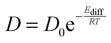
The temperature dependence of the diffusion coefficients is obtained by fitting the diffusion coefficient curve against an Arrhenius law:
Diffusion coefficients were calculated from the MSD following the methodology described above and implemented in GROMACS.42
III Experimental section
III-1 The ice film preparation
The experiments were performed using the RING experimental set-up as described elsewhere.48 A gold plated copper surface is maintained at low temperature using a closed-cycle helium cryostat (ARS Cryo, model DE-204 SB, 4 K cryogenerator) within a high-vacuum chamber at a few 10−9 hPa. The sample temperature is measured with a DTGS 670 silicon diode with a 0.3 K uncertainty. The temperature is controlled using a Lakeshore Model 336 temperature controller and a heating resistance. Infrared absorption spectra are recorded in the reflection absorption mode by means of Fourier transform reflection absorption infrared (FTIR-RAIRS) spectroscopy using a Vertex 70 spectrometer with either a DTGS detector or a liquid N2 cooled MCT detector. A typical spectrum has a 1 cm−1 resolution and is averaged over a few tens of interferograms.Water vapor is obtained from deionized water, which was purified by several freeze–pump–thaw cycles, carried out under primary vacuum. Gas-phase CO2 is commercially available in the form of 99.9995% pure gas from Air Liquide. Gas-phase H2O and CO2 are mixed together at room temperature in a primary pumped vacuum line using standard manometric techniques, with CO2 mixing ratios of a few percent. Then the homogeneously mixed gas-phase mixture is sprayed onto the cold gold plated copper surface at a normal incidence at 80 K to give a homogeneously mixed CO2![[thin space (1/6-em)]](https://www.rsc.org/images/entities/char_2009.gif) :H2O ice mixture, with a large excess of amorphous solid water (ASW), as displayed in Fig. 1. The 80 K deposition temperature is chosen to obtain a compact morphology of the amorphous ice (c-ASW) and prevent the diffusion on the open pores surface. At 80 K the pore collapse was measured at 1.7 × 10⁻⁴ s−1,33i.e. a characteristic time of approximately an hour and a half. Fig. 2 shows the characteristic spectra we get for CO2:H2O mixtures.
:H2O ice mixture, with a large excess of amorphous solid water (ASW), as displayed in Fig. 1. The 80 K deposition temperature is chosen to obtain a compact morphology of the amorphous ice (c-ASW) and prevent the diffusion on the open pores surface. At 80 K the pore collapse was measured at 1.7 × 10⁻⁴ s−1,33i.e. a characteristic time of approximately an hour and a half. Fig. 2 shows the characteristic spectra we get for CO2:H2O mixtures.
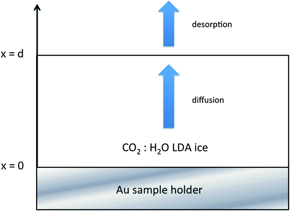 | ||
| Fig. 1 Scheme of the ASW film of thickness d, where the CO2 is homogeneously mixed in the dominant ASW at the initial time. The one-dimension diffusion of the CO2 molecules along the x direction is monitored at a fixed temperature by recording the evolution of its characteristic IR absorption bands as a function of time using FTIR spectroscopy. The diffusion boundary conditions at the surface are a null flow at x = 0 and a flow set by the desorption rate at x = d. | ||
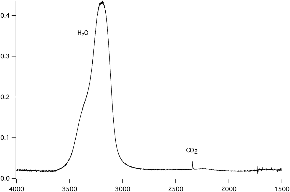 | ||
| Fig. 2 Infrared absorption spectrum at 120 K of CO2 homogeneously mixed in c-ASW ice, deposited at 80 K in a 1.4:100 CO2:H2O concentration ratio. | ||
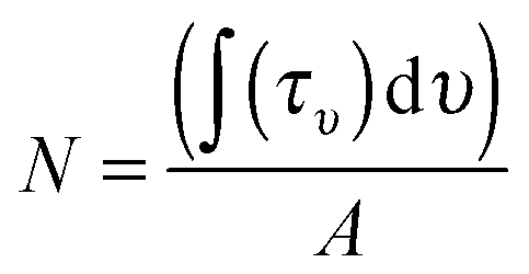
The column density N (molecules cm−2) of each molecular species is derived from the IR absorption spectrum right after deposition from the film IR spectra, as seen in Fig. 2, using the expression
Carbon dioxide is identified by its asymmetric stretching mode at 2342 cm−1 and its bending mode band at 667 cm−1. The band strength for the CO2 asymmetric stretching band was measured to be 7.6 × 10⁻¹⁷ cm molecule−1 for the pure solid,49,50 while in water ice a value of 1.4 × 10⁻¹⁷ cm molecule−1 was found.51 Water ice has three characteristic bands at 3280, 1660 and 760 cm−1 corresponding to the OH stretching, HOH bending and libration modes respectively. The corresponding band strengths are 2.1 × 10⁻¹⁶, 3.1 × 10⁻¹⁷ and 3.1 × 10⁻¹⁷ cm molecule−1, respectively.50 There is an approximate 30% uncertainty on the band strengths and so on the calculated column densities.
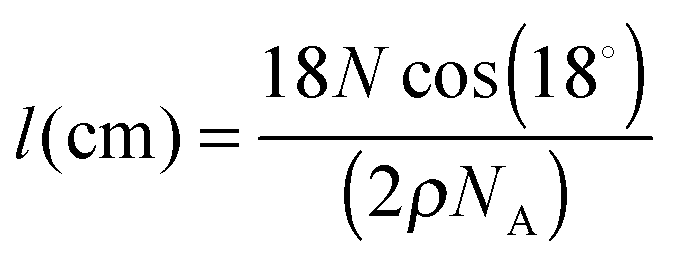
The ASW ice film thickness l the CO2 molecules need to diffuse through is an important parameter in our experiment. The method we used to measure it is based on the quantity of matter as determined from the IR absorption bands, using the H2O OH stretching band. The ASW thickness l is derived from the measured column density N (molecule cm−2) using ρ = 0.94 g cm−3 as the amorphous ice density, and using
Since the ice sample can be modeled as a cylinder of a few centimeters diameter and a few hundreds of nanometers thick, and since the IR beam has a smaller diameter, we can reasonably assume that the CO2 molecules are mainly diffusing along the x direction within the ASW layer and that a negligible amount of them escape from the cylinder side. The diffusion problem can be treated as one-dimensional diffusion within an infinite ice sheet. The different deposited samples and related experiments are summarized in Table 3.
| Experiment number | Morphology | Temp. (K) | Initial ratio | Deposition temperature (K) | Thickness (nm) |
|---|---|---|---|---|---|
| 1 | Compact | 95 | 5.2 | 80 | 194 |
| 2 | Compact | 100 | 5.8 | 80 | 40 |
| 3 | Compact | 100 | 0.3 | 100 | 75 |
| 4 | Compact | 120 | 6.2 | 80 | 183 |
| 5 | Compact | 120 | 0.2 | 100 | 48 |
| 6 | Compact | 130 | 1.8 | 100 | 62 |
| 7 | Compact | 135 | 6.2 | 80 | 93 |
| 8 | Compact | 140 | 8.5 | 80 | 514 |
| 9 | Compact | 140 | 0.3 | 100 | 67 |
| 10 | Compact | 140 | 0.3 | 100 | 28 |
| 11 | Compact | 140 | 0.2 | 100 | 12 |
| 12 | Compact | 150 | 0.2 | 100 | 37 |
| 13 | Porous homogeneous | 100 | 0.36 | 15 | 22 |
III-2 The kinetics of the ASW film pore collapse
The morphology of the ice depends on the temperature of the gold surface the water vapor is deposited on. Once deposited the ASW (porous p-ASW or compact c-ASW for low- and high-deposition temperatures respectively) is metastable and will tend to reach a thermodynamically equilibrium state. The pore structure will collapse and the amorphous structure will reorganize into an organized crystalline network. This way the equilibrium can be decomposed by phase transitions, from an initial high-density amorphous ice Ia h (temperature deposition at 15 K) to a low-density amorphous ice Ia l between 38 K and 68 K, and possibly a third amorphous form Ia r preceding the crystallization into cubic ice Ic 1. Because of the deposition temperature we choose, our ice does not undergo the high density to low density transition. Ice porosity is visible from the small OH dangling bands at 3720 and 3696 cm−1, indicating a large effective surface.52,53 Once slightly warmed up these dangling bands quickly disappear, indicating the start of the pore collapse and the decrease of the effective surface. The ice samples we prepared have a small surface to volume ratio as indicated by the absence of OH dangling bands in our spectra as seen in Fig. 2. The pore collapse also induces modifications of the OH stretching band. The pore collapse kinetics can be estimated from the changes in the OH stretching band.33,54 Fitting the experimental kinetic rates measured in ref. 33 between 40 K and 120 K with an Arrhenius law gives an approximate 0.8 ± 0.1 kJ mol−1 reorganization energy, with a 6.5 ± 1.5 × 10⁻⁴ s−1 pre-exponential factor. This reorganization is fast. For example at the onset of crystallization, at 150 K, it is around 18 minutes.33 In the interstellar medium, at 10 K, it is approximately 9 months, which is nothing on an interstellar timescale. Above 120–140 K the crystallization kinetics takes over the reorganization process which precedes it. Both the deposition temperature we have chosen, 80 K, and the temperature interval we are working in ensure that the ASW ice is compact, with a small surface to volume ratio, and that we are measuring volume diffusion mainly.III-3 The isothermal kinetic experiments on CO2
In isothermal kinetic (IK) experiments, right after deposition, the ice film is heated as fast as possible to a fixed target temperature T, in typically a few tens of seconds. Once the target temperature T is reached, we set the initial time t = 0 s of our isothermal kinetics. Assigning a “time zero” can be difficult because of the time it takes to reach the isothermal temperature. If the deposition temperature is close to the target temperature the uncertainties are small, ca. a few seconds, but the error can be significant for low temperature deposition, ca. a few tens of seconds, which is nevertheless small compared to hours long kinetics. In an IK experiment, the CO2 molecules diffuse within the water ice film, up to the top surface of the ice, and then desorb. The diffusion–desorption of CO2 along the x direction at the fixed temperature T is monitored by recording its abundance decay from its characteristic absorption band at 2342 cm−1 as a function of time, until it reaches a plateau, as shown in Fig. 3 for several temperatures. The IR decay curve is directly related to the CO2 molecules diffusion in the compact ASW ice. The decay curves are normalized to the initial CO2 abundance.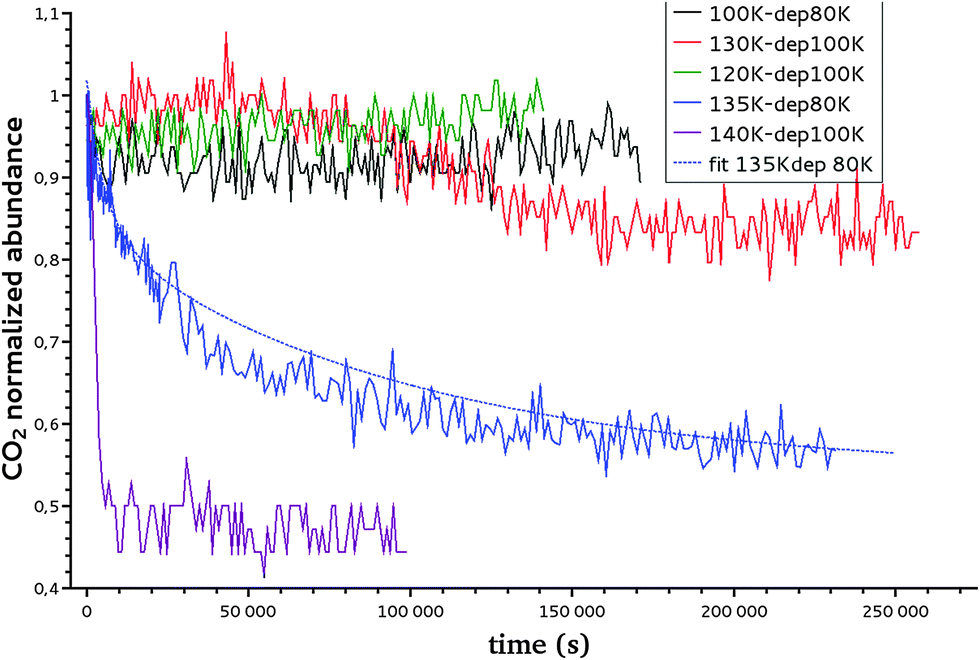 | ||
| Fig. 3 Decay curve of CO2 at temperatures ranging from 100 to 140 K using two different deposition temperatures (80 K and 100 K) as presented in the legend. An example of the fit, using the formula introduced in Section III-3, of the CO2 decay curve at 135 K is plotted with a dashed line. | ||
The temperature range that can be accessed to is limited. The lowest temperature is set by the time duration and the long-term stability of the experiment, i.e. by the deposition of residual water on top of the ASW film and the consequent increase in the ASW ice thickness. Within our vacuum conditions, ca. at a few 10−9 hPa, the time to grow ca. 10% of the initial thickness corresponds to approximately three days. The highest accessible temperature is set by the ASW substrate desorption compared to the time needed to acquire one spectrum. The H2O desorption rate constant is k(H2O) = 1015 s−1 × exp(46.6 kJ mol−1/RT),55 which corresponds to a residence time of 240 s at 140 K and 17 s at 150 K. At 150 K, the ASW desorption rate is too high and prohibits IK studies. Fig. 4 shows that at T = 150 K the CO2 decay curve is not due to diffusion but due to the water ice substrate desorption. Therefore we will consider IK experiments between 95 K and 140 K only.
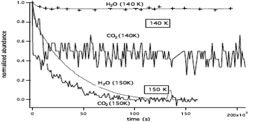 | ||
| Fig. 4 Decay curve of CO2 (solid line) and H2O (dashed line) at 140 K and 150 K. At 140 K there is almost no co-desorption, while at 150 K the co-desorption mechanism is dominant. | ||
The reproducibility and the dispersion of the experiments are estimated by measuring the decay of CO2 at 140 K (experiments 8, 9, 10 and 11 in Table 3). The four experiments show decay rates of the same order of magnitude (8.4 × 10⁻⁴ s−1, 4.2 × 10⁻⁴ s−1, 3.6 ×10⁻⁴ s−1, 1.6 × 10⁻⁴ s−1, respectively).
The CO2 abundance decay curves are fitted using a one-dimension diffusion equation in a plane sheet, where the boundary condition at the x = 0 surface is given by a null flow and where the boundary condition at the free surface is set by the CO2 desorption rate. The initial concentration is C0 at t = 0. We chose temperatures for which the CO2 residence time on top of the ice surface (x = 1) is much smaller than the diffusion time, so that we have an infinite desorption rate and therefore a null concentration at x = 1. Since we never totally deplete the initial CO2 reservoir, we can make the assumption that the concentration at x = 0 is kept constant at C0. In that case the total amount of CO2 present at time t in the plane ice sheet, normalized to the initial quantity, is56
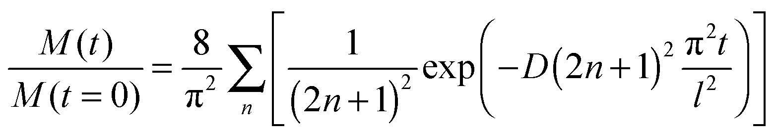
The quantity M(t)/M(t = 0) is the experimentally measured quantity as shown in Fig. 3.
For some of the temperatures, it was not possible to derive a diffusion coefficient, but rather an upper limit for the diffusion coefficient for a given thickness and temperature. The experimental results are presented in Table 4 and can be viewed in Fig. 9b. They are discussed with respect to the calculated values in Section IV-4. One must emphasize that the decay curve fitting depends on the estimated final value of the curves, which is taken arbitrarily, and not set to zero as we might theoretically expect. This remaining CO2 problem has been previously observed in Mispelaer et al.33 and will be discussed in Section IV-4.
| Temperature (K) | Experiment number | D mes. (cm2 s−1) |
|---|---|---|
| 100 | 3 | <1 × 10⁻¹⁴ |
| 120 | 4 | (2 ± 4) × 10−12 |
| 120 | 5 | <1 × 10⁻¹⁴ |
| 130 | 6 | (8.2 ± 1) × 10−13 |
| 135 | 7 | (8.6 ± 1) × 10−13 |
| 140 | 8 | (3.5 ± 1) × 10−11 |
| 140 | 9 | (2.5 ± 1) × 10−12 |
| 140 | 10 | (1.4 ± 1) × 10−12 |
| 140 | 11 | (1.7 ± 1) × 10−12 |
IV The molecular dynamics simulations for diffusion in a LDA ice
IV-1 The LDA ice structure
The LDA ice structure equilibrated at various temperatures and obtained by employing the TIP4P effective potential, including for the H2O solute molecule, is defined by us as a “reference system”, and this notation will be used later in the text.In order to ensure that the ice structures, resulting from the methodology described in Section II-2, have the required local structure of LDA ices, we computed for the “reference system” the O–O radial distribution function (RDF), gOO(r), at 170 K, 105 K and 60 K.
Fig. 5 shows that our calculated gOO(r) behaves similarly for the three temperatures. The curves exhibit two peaks corresponding to the two first solvation shells at 2.75 Å and 4.5 Å respectively, and a deep minimum at 3.1 Å. These peaks (positions and relative intensities) are very similar to those found experimentally by Finney et al.43 and Bowron et al.45 using neutron diffraction, and from molecular dynamics simulations by Martoňák et al.11,12 The existence of these peaks is an indication of a local structural organization in the LDA ice, whereas the amorphous character of the ice model can be concluded from the gOO(r) at r > 5 Å, where the fast averaging of the oxygen density evidences the non-existence of crystallinity as expected for a LDA ice. The peak intensities vary with the temperature. This is more pronounced for the first peak at 2.75 Å: a lower intensity being associated with a decrease of the local structural organization. Our calculated gOO(r) indicates, as expected, a higher structural organization of the ice for lower temperature. The positions of the peaks are the same for the three temperatures demonstrating that the LDA ice structure is preserved in the interval of T = 60 to 170 K.
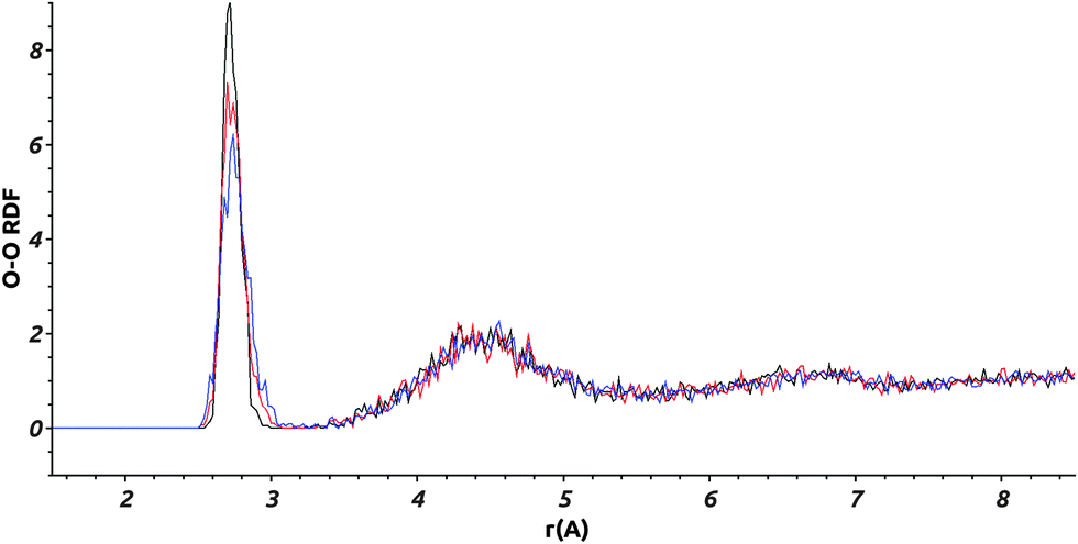 | ||
| Fig. 5 Calculated O–O RDF: gOO(r), for the “reference system” for three different temperatures: 170 K in blue, 105 K in red, and 60 K in black. | ||
Our calculated RDF, at 170 K, using the TIP4PQ/2005 and the TIP4P potential models are compared in Fig. S2 (ESI†). One can see from this comparison that the two peaks corresponding to the first solvation shells are shifted toward smaller distances (2.65 Å and 4.35 Å) in the case of TIP4PQ/2005, confirming the nonadequacy of this potential to describe LDA ices.
We note here that the radial distribution functions for the larger cell of 540 water molecules were also computed. There is no difference with the reference system as follows from the results reported in Fig. S3 (ESI†).
In order to evaluate the porosity of the modeled ice, a cavity distribution calculation was carried out using the SURFNET program.57 This program allows for the calculation of the position and volume of the cavities present in the ice. Fig. 6 is a snapshot of our LDA ice where water and cavities are shown.
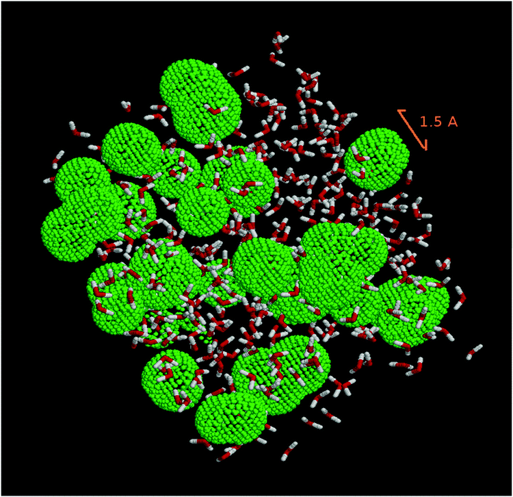 | ||
| Fig. 6 Snapshot of the system studied. Water molecules are shown in a ball-and-stick representation. Green beads delineate the cavities in amorphous ice. | ||
The cavity distribution was then built by calculating the size and the volume of the cavities for each step and averaging for 1000 steps of the molecular dynamics. The distributions of the cavity radii and volumes are shown in Fig. 7 at 170 K and 105 K.
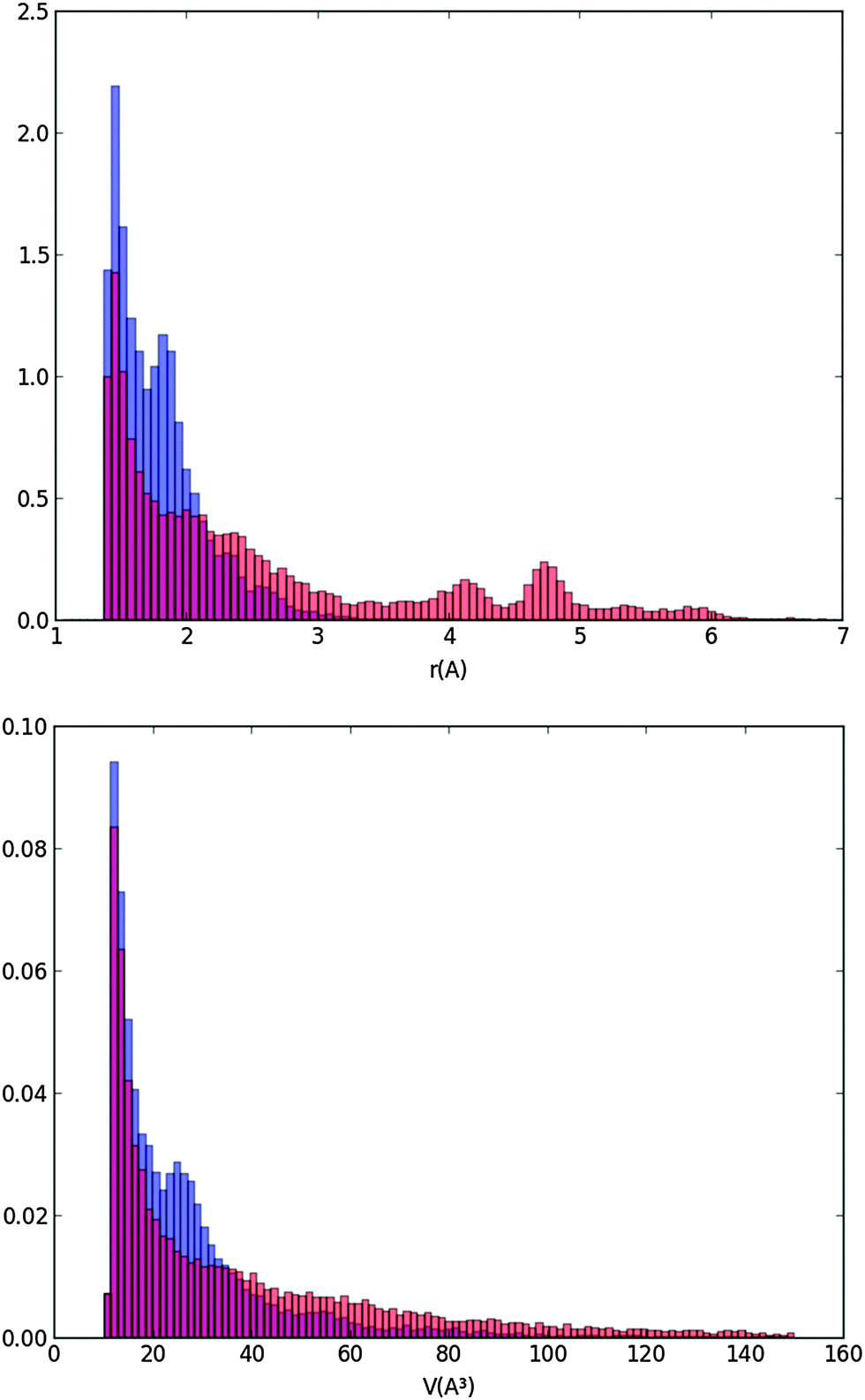 | ||
| Fig. 7 Distributions of normalized cavity radii and volumes at two characteristic temperatures of 170 K in orange and 105 K in blue (the red color corresponds to the overlap of the blue and orange colors). | ||
Fig. 7 shows that the majority of the cavities of our ice model are very small with radii below 2 Å. They are much smaller than a “vacancy” representing the volume leftover when a water molecule is absent and for which, from our calculated distance of the first solvation layer (Fig. 5), we expected a radius of 2.8 Å minimum. The cavities we calculate are likely due to the statistical motion of the water molecules of our ice water box creating small interstices. Our LDA ice is evidently not porous since pores would appear with at least the radius of a vacancy. We have also calculated the densities of the ice at various temperatures. They range between 0.98 g cm−3 (T = 60 K) and 0.96 g cm−3 (T = 170 K). They are very close to the density of 0.97 g cm−3 determined by Martoňák et al.11,12 at 80 K and zero pressure for the same type of ice, and to the experimental density of 0.94 g cm−3 measured at 117 K.44 The size of the cavities of our LDA ice model and its density confirm its compactness and therefore its relevance for modeling astrophysical ices for T = 60–170 K.
IV-2 Water self-diffusion and diffusion of a water molecule in a LDA ice
In this section, we are comparing the calculated “water self-diffusion” in a LDA ice with “water diffusion” in the same ice. We recall that in the former case, all molecules of the simulation box, all described with the TIP4P effective potential (i.e. the “reference system”), are considered as diffusive molecules. In the later case, only the motion of one solute H2O molecule in the LDA ice is considered. In this last case, the diffusing water molecule is described using the TIP3P effective potential while the remaining water molecules composing the ice are described using the TIP4P effective potential. Such a comparison is undertaken to validate our approach for the diffusion coefficient calculations of a solute molecule in a LDA ice (Section IV-3). Molecular diffusion trajectories of 1 μs were considered to calculate the water self-diffusion coefficients while these trajectories were extended to 5 μs for the “water diffusion” coefficients calculations.Our calculated O–O radial distribution functions for the “reference system” and the LDA ice containing one solute molecule (Fig. S6 of ESI†) are identical, both in very good agreement with available data from the literature.11,12,43–45
Fig. 8 reveals that the calculated diffusion coefficients follow different regimes: a “high temperature” regime above 170 K, a “medium temperature” regime between 170 K and 90 K, and a “low temperature” regime below 90 K. Below 90 K, an asymptotic behavior is observed. These plateaus are an indication that at low temperatures, the mean square displacements from the MD simulations are too small to determine the diffusion coefficients with a good precision. Indeed the MSD derived from the trajectories at 170 K and 60 K and reported in Fig. S7 and S8 (ESI†), respectively, show at 170 K a linear MSD behavior with time, while at 60 K the MSD curve is flat and difficult to extract from the noise. We conclude that the present MD calculations are not able to give diffusion coefficients for temperature below 90 K, as are the IK experiments.
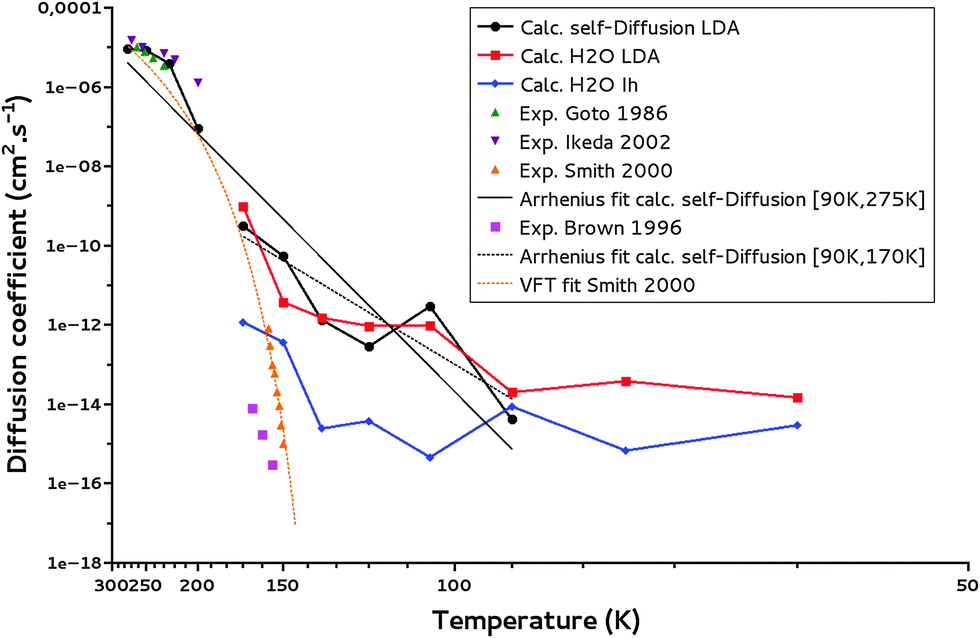 | ||
| Fig. 8 Water self-diffusion (calc. self-Diffusion LDA), water diffusion coefficients (calc. H2O LDA) calculated for a LDA ice and water self-diffusion coefficients calculated for a crystalline ice (calc. self-Diffusion Ih). The Arrhenius fits for T = 90–170 K and T = 90–275 K of calculated self-diffusion coefficients (Arrhenius fit calc. self-Diffusion) are reported. Experimental data from the literature: Smith et al.,32 Brown et al.,62 Ikeda-Fukazawa et al.,14 Goto et al.,63 as well as the VFT fit from Smith et al.32 are given for comparison. | ||
Our simulations between 170 and 90 K are of interest for the present study. The ice model is of LDA type as confirmed from the calculated gOO(r) and ρLDA at these temperatures (as well as calculated cavity distributions at 170 K and 150 K). These temperatures correspond to those where diffusion and thermal reactivity could occur at reasonable timescales in the interstellar medium.6 Indeed, it has been shown that in the laboratory for conditions mimicking those in the interstellar medium, NH3 and CO2 react to form ammonium carbamate in 3 hours at 90 K.58
In our limited temperature interval, the calculated diffusion coefficients exhibit an Arrhenius behavior (linear from Fig. 8), decreasing with temperature as expected, very similarly for both the self-diffusion and the water molecule diffusion. The calculated water self-diffusion coefficients and the calculated diffusion coefficients of a water molecule in the same LDA ice are reported in Table 5. They compare very satisfyingly regarding the uncertainty of our calculations (of an order of magnitude at most from our calculations).
| Temperature (K) | D self-D LDA (cm2 s−1) | D H2O LDA (cm2 s−1) | D calc. self-D Ih (cm2 s−1) |
|---|---|---|---|
| 60 | (2.1 ± 3.0) × 10−15 | (1.5 ± 2.6) × 10−14 | (3.0 ± 6.0) × 10−15 |
| 75 | (1.9 ± 1.8) × 10−15 | (3.8 ± 5.2) × 10−14 | (6.8 ± 3.3) × 10−15 |
| 90 | (4.16 ± 0.04) × 10−15 | (2.0 ± 3.2) × 10−14 | (8.8 ± 1.4) × 10−14 |
| 105 | (3.0 ± 5.9) × 10−12 | (9.7 ± 9.9) × 10−13 | (4.6 ± 3.4) × 10−15 |
| 120 | (2.9 ± 1.1) × 10−12 | (9.5 ± 1.8) × 10−12 | (3.8 ± 3.5) × 10−15 |
| 135 | (1.4 ± 5.5) × 10−12 | (1.5 ± 4.8) × 10−12 | (2.4 ± 5.4) × 10−15 |
| 150 | (5.4 ± 3.1) × 10−11 | (3.8 ± 3.9) × 10−12 | (3.7 ± 1.2) × 10−14 |
| 170 | (3.2 ± 6.4) × 10−11 | (9.9 ± 1.4) × 10−10 | (1.2 ± 6.5) × 10−13 |
The self-diffusion coefficients derived from molecular dynamics trajectories computed for the larger 2.57 nm water cell are compared to the self-diffusion coefficients calculated for the 2.25 nm reference system (Fig. S9 of ESI†). Their similarity as well as the very good agreement of radial distribution functions and densities, computed for both water box sizes, justified our choice to use the smaller box with 350–380 water molecules to study the diffusion of molecules in a LDA ice.
Using the Arrhenius formula defining the temperature dependence of the diffusion coefficients, the activation energies were estimated from the self-diffusion and water molecule diffusion calculations for T = [170–90 K]. They are 15 ± 5 kJ mol−1 and 13 ± 5 kJ mol−1 with pre-exponential factors of (7 ± 1) 10−6 cm2 s−1 and (9 ± 1) 10−7 cm2 s−1, respectively, and are reported in Table 7.
Following the Vogel–Fulcher–Tammann (VFT) law for glass, as given below,
The experimental self-diffusion coefficients determined by Smith et al.32 in an amorphous solid water ice are in orange in Fig. 8. They range from 10−15 to 10−12 cm2 s−1 for temperature between 150 K and 160 K. The variation with temperature of these self-diffusion coefficients is attributed to an amorphous solid ice glass transition into a quasi-liquid phase prior to crystallization.59,60 However at 150 K, crystallization kinetics have been proved to be a minute-scale phase transition,61 so that the diffusion coefficient of 10−15 cm2 s−1 determined experimentally at 150 K might account for an ice in a crystalline phase explaining its discrepancy with our calculated one at the same temperature in the LDA ice but its agreement with our calculated one in a crystalline ice (10−14 cm2 s−1 at 150 K).
Brown et al.62 measured diffusion coefficients for H218O in a crystalline H216O ice, of 10−16–10−14 cm2 s−1 for T = 155–165 K. These values are much lower than our calculated amorphous water ice diffusion coefficient of 10−12 cm2 s−1 at 150 K while closer to our calculated one in a crystalline Ih ice of 10−14 cm2 s−1 at 150 K (see also Fig. 8). As expected the self-diffusion of water in an amorphous ice is a couple of orders of magnitude faster than in a crystalline ice.
To allow for further comparison of our theoretical calculations with data from the literature16,63 we have calculated the water ice “self-diffusion” coefficients for higher temperatures. Between 200 and 270 K they range from 10−7 to 10−5 cm2 s−1 comparing satisfyingly with the experimental data of Goto et al. in crystalline ice63 of 10−6–10−5 cm2 s−1 measured between 230 and 260 K (see Fig. 8). Ikeda et al.16 calculated water diffusion coefficients in ice Ih to be 10−6–10−5 cm2 s−1 at T = 200–270 K. The radial distribution functions for these high-temperature simulations are shown in Fig. S5 (ESI†). One can see that the RDFs lose their structures, as temperature increases. The densities also increase as shown in Fig. S4 (ESI†): a tendency expected for an ice to liquid water transition.
We have carried out a supplementary fit using our water self-diffusion coefficients including the supercooled liquid points and considering temperatures from 90 K to 275 K. Comparing the resulting fit with the fitted values of Smith et al.32 following the VFT law (in orange in Fig. 8), we can state that as expected diffusion in amorphous ice, which is generally understood as diffusion in liquid water, is better described by an Arrhenius law.64 The successful inclusion of the supercooled liquid zone in the fit argues for the same diffusion mechanism for both the LDA ice and the supercooled water; this certainly characterizes a viscous-like diffusion.
The similarity of our results (considering our one order of magnitude uncertainty) for both the self-diffusion and water diffusion approaches and the agreement of our results with measured values argue for the validity of our protocol to calculate diffusion coefficients of molecules by considering a molecule diffusing in a LDA ice of 350 to 380 water molecules for MD trajectory of 5 μs. This protocol was used to calculate the diffusion coefficients of CO, CO2, NH3, and H2CO in the same LDA ice.
IV-3 Diffusion of CO, CO2, NH3, and H2CO in a LDA ice
We have calculated diffusion coefficients for CO, CO2, NH3 and H2CO, in the LDA ice model. Their diffusion coefficients are reported in Fig. 9a–d, along with water self-diffusion coefficients, for temperature ranging between 170 K and 90 K. We did not report our calculated diffusion coefficients below 90 K because they are not reliable, as discussed above.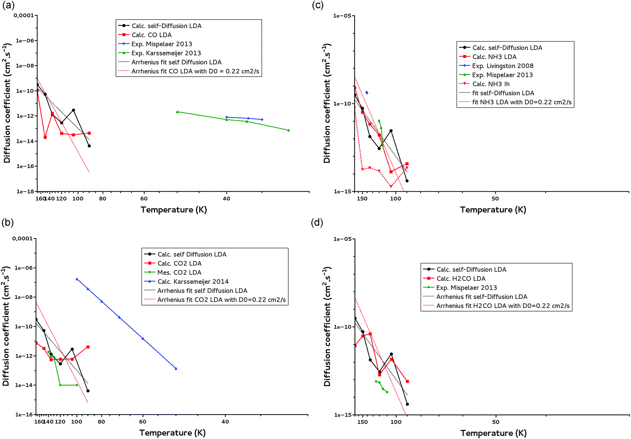 | ||
| Fig. 9 (a) CO diffusion coefficients calculated for a LDA ice (calc. CO LDA) and comparison with water self-diffusion (calc. self-Diffsion LDA) coefficients calculated for the same ice for T = 90–170 K. The Arrhenius fit (T = 90–170 K) of the self-diffusion is added. Experimental data of Mispelaer et al.33 and Karssemeijer et al.29 are reported respectively in blue and green for comparison. (b) CO2 diffusion coefficients calculated for a LDA ice (calc. CO2 LDA) and comparison with water self-diffusion (calc. self-Diffusion LDA) coefficients calculated for the same ice for T = 90–170 K. The Arrhenius fit (T = 90–170 K) of the self-diffusion is added. Our measured CO2 diffusion coefficients are given in green and calculated points of Karssemeijer et al.28 in blue. (c) NH3 diffusion coefficients calculated for a LDA ice (calc. NH3 LDA) and for a Ih crystalline ice (calc. NH3 Ih) and comparison with water self-diffusion (calc. self-Diffusion LDA) coefficients calculated for the LDA ice for T = 90–170 K. The Arrhenius fit (T = 90–170 K) of the self-diffusion is added. Experimental points of Livingston et al.30 and Mispelaer et al.33 are given respectively in blue and green. (d) H2CO diffusion coefficients calculated for a LDA ice (calc. H2CO LDA) and comparison with water self-diffusion (calc. self-Diffusion LDA) coefficients calculated for the same ice for T = 90–170 K. The Arrhenius fit (T = 90–170 K) of the self-diffusion is also reported. Experimental points of Mispelaer et al.33 are given in green. | ||
Fig. 9a–d show that in the 90–170 K temperature range, the diffusion coefficients of CO, CO2, NH3 and H2CO present the same dependence on temperature as the water self-diffusion despite their difference in mass, geometry, polarizability, dipole moment and ability to make hydrogen bonding. A deeper analysis of these diffusion coefficients is possible from Table 6 where they are reported together with the available experimental diffusion coefficients of NH3, CO CO2 and H2CO measured in LDA ices.
| (a) | |||
|---|---|---|---|
| Temperature (K) | D calc. CO LDA (cm2 s−1) | D exp. Mispelaer et al.33 | D calc. Karssemeijer et al.28 |
| 32 | 7.4 × 10⁻¹⁴ | ||
| 35 | (5.2 ± 4.7) × 10−13 | ||
| 36.8 | (6.8 ± 5.9) × 10−13 | ||
| 37 | 3.7 × 10⁻¹³ | ||
| 40 | (8.0 ± 7.3) × 10−13 | 5.1 × 10⁻¹³ | |
| 50 | 2.2 × 10⁻¹² | ||
| 90 | (4.4 ± 3.6) × 10−14 | ||
| 105 | (3.1 ± 6.6) × 10−14 | ||
| 120 | (4.2 ± 1.1) × 10−13 | ||
| 135 | (1.6 ± 7.7) × 10−13 | ||
| 150 | (2.0 ± 4.0) × 10−13 | ||
| 170 | (1.1 ± 5.3) × 10−11 | ||
| (b) | |||
|---|---|---|---|
| Temperature (K) | D calc. CO2 LDA (cm2 s−1) | D mes. CO2 (cm2 s−1) | D exp. Karssemeijer et al.29 |
| 50 | 1.4 × 10⁻¹³ | ||
| 60 | 1.5 × 10⁻¹¹ | ||
| 70 | 4.3 × 10⁻¹⁰ | ||
| 80 | 5.3 × 10−09 | ||
| 90 | (4.2 ± 1.2) × 10−11 | 3.7 × 10−08 | |
| 100 | 5.9 × 10 −14 | <1 × 10⁻¹⁴ | 1.8 × 10−07 |
| 105 | (5.9 ± 2.9) × 10−13 | — | |
| 120 | (5.9 ± 1.3) × 10−12 | (2 ± 4) × 10−12 | |
| 130 | 9.2 × 10 −13 | (8.2 ± 1) × 10−13 | |
| 135 | (5.5 ± 9.7) × 10−13 | (8.6 ± 1) × 10−13 | |
| 140 | 1.76 × 10 −12 | (2.5 ± 1) × 10−12 | |
| 150 | (3.3 ± 2.9) × 10−12 | — | |
| 170 | (7.7 ± 1.7) × 10−12 | — | |
| (c) | ||||
|---|---|---|---|---|
| Temperature (K) | D calc. NH3 LDA (cm2 s−1) | D calc. NH3 Ih (cm2 s−1) | D exp. Livingston et al.30 | D exp. Mispelaer et al.33 |
| 90 | (3.9 ± 5.0) × 10−14 | (2.3 ± 1.1) × 10−14 | ||
| 105 | (1.3 ± 4.9) × 10−14 | (1.9 ± 1.9) × 10−13 | ||
| 115 | (4.5 ± 4.1) × 10−13 | |||
| 117 | (4.5 ± 4.1) × 10−12 | |||
| 120 | (1.6 ± 3.0) × 10−12 | (1.5 ± 8.3) × 10−14 | (1.1 ± 1.0) × 10−11 | |
| 135 | (6.9 ± 3.2) × 10−12 | (2.2 ± 5.3) × 10−14 | ||
| 140 | 4 × 10⁻¹⁰ | |||
| 141.2 | 4.5 × 10⁻¹⁰ | |||
| 150 | (3.3 ± 2.9) × 10−11 | (1.8 ± 3.4) × 10−14 | ||
| 170 | (8.1 ± 1.1) × 10−9 | (5.8 ± 1.1) × 10−10 | ||
| (d) | ||
|---|---|---|
| Temperature (K) | D calc. H2CO LDA (cm2 s−1) | D exp. Mispelaer et al.33 |
| 90 | (8.1 ± 9.0) × 10−14 | |
| 105 | (1.5 ± 3.0) × 10−12 | |
| 110 | (2.0 ± 1.8) × 10−14 | |
| 115 | (3.0 ± 2.7) × 10−14 | |
| 120 | (1.9 ± 3.4) × 10−12 | (7.0 ± 6.4) × 10−14 |
| 125 | (8.0 ± 7.3) × 10−14 | |
| 135 | (4.1 ± 4.3) × 10−11 | |
| 150 | (3.1 ± 1.7) × 10−11 | |
| 170 | (8.7 ± 2.2) × 10−11 | |
Using the above Arrhenius formula, activation energies were estimated from the diffusion calculations for T = [170–90 K]. They are reported in Table 7.
| System | D 0 (cm2 s−1) | E a (kJ mol−1) | E a (kJ mol−1) with D0 = 0.22 cm2 s−1 |
|---|---|---|---|
| H2O Self-D LDA | (7 ± 1) × 10−06 | 15 ± 5 | 24.9 ± 2.9 |
| H2O Self-D Ih | (1 ± 0.2) × 10−10 | 9 ± 5 | |
| NH3 LDA | (3 ± 0.5) × 10−05 | 17 ± 5 | 25.4 ± 1.0 |
| NH3 Ih | (7 ± 2) × 10−10 | 9 ± 5 | |
| CO2 | (3 ± 0.5) × 10−10 | 3 ± 3 | 25.0 ± 2.4 |
| CO | (2 ± 0.5) × 10−09 | 8 ± 5 | 27.2 ± 2.1 |
| H2CO | (1.7 ± 0.5) × 10−08 | 9 ± 5 | 25.0 ± 1.7 |
| H2O | (9 ± 1) × 10−07 | 13 ± 5 | 25.3 ± 1.3 |
From Table 6a–d one can see that the calculated diffusion coefficients are rather similar while corresponding to molecules with different physical properties (mass, dipole moment, polarizability, hydrogen bonding). In between 120 K and 135 K they are of the order of 10−12 cm2 s−1 for H2O self-diffusion, 10−13–10−12 cm2 s−1 for the diffusion of CO2, 10−12 cm2 s−1 for NH3, 10−11–10−12 cm2 s−1 for H2CO and 10−13 cm2 s−1 for CO. At 150 K they are of the order of 10−11 cm2 s−1 for H2O self-diffusion, 10−12 cm2 s−1 for the diffusion of CO2, 10−11 cm2 s−1 for NH3 and H2CO and 10−13 cm2 s−1 for CO. Taking into account the one order of magnitude uncertainty of our calculations, we confirm the trend already observed from Fig. 9a to d that the diffusion in these LDA ices is driven by the diffusion of the water molecules of the ice, regardless of the solute molecule diffusing in. The classification suggested by Collings et al.34 for desorption can obviously not be transposed to bulk diffusion in amorphous water ice.
IV-4 Discussion
Let us now compare our calculated bulk diffusion coefficients of CO, CO2, NH3 and H2CO with the experimentally measured ones (or tentatively measured in the case of CO) in the bulk of LDA ices. Table 6 shows that within the experimental and theoretical uncertainties, i.e. one order of magnitude for both, we can argue for a rather satisfying agreement between the calculated diffusion coefficients and the experimental one for CO2, NH3 and H2CO, validating our molecular dynamics simulations and therefore our suggestion above of a diffusion mechanism driven by the diffusion of the water ice molecules. The case of CO2 is important since its diffusion does not involve hydrogen bond breaking. We do not observe the same agreement for CO for which the experimentally measured diffusion is expected to be dominated by surface diffusion even at low temperature because of its low desorption energy (9.8 kJ mol−1) and the experimental difficulties to get compact ices at such low temperatures. Indeed, at these low temperatures, the ices are very porous, allowing for the diffusion of CO through the pores towards the surface. The diffusion coefficients measured for CO, much higher than what would be expected for bulk diffusion, are consistent with the surface diffusion coefficients calculated by Karssemeijer for CO and CO228,29 (see Fig. 9a and c).Our calculated diffusion coefficients for NH3 in a crystalline ice (Table 6) are of the order of 10−14 cm2 s−1 between 90 K and 150 K. At 140 K Livingston30 measured in a crystalline ice a bulk diffusion coefficient for NH3 of 4.0 × 10⁻¹⁰ cm2 s−1. This value is higher than our diffusion coefficient calculated in the crystalline ice (but closer to the one in the LDA ice). Two explanations are possible. (i) As discussed in Livingston et al.30 the high diffusion coefficient measured might be related to a crystalline ice lattice disruption. Breaking the lattice would generate vacancies causing the ammonia to move via a faster surface diffusion. (ii) Taking into account that during our molecular dynamics no destruction of the crystalline lattice is observed, it is clear that our calculations cannot account for a bulk diffusion mechanism mediated by vacancy formation.
We have derived activation energies for the diffusion of CO, CO2, NH3 and H2CO from our Arrhenius fits. They are given in Table 7. One can notice that the activation energies might be related to the polarity of the molecule with CO2 presenting the lowest activation energy and H2O and NH3 the highest one. The height of the activation energies might also be related to the ability of the molecules to build hydrogen bonds. Our activation energies compare rather well with the experimental values of Mispelaer et al.:33 for instance, for CO and H2CO the measured activation energies are respectively 1 and 12 kJ mol−1 which are in the same range as ours (8 and 9 kJ mol−1, respectively). A larger discrepancy is observed for ammonia with an experimental value of 71 kJ mol−1 and a theoretical one of 17 kJ mol−1. However the agreement between corresponding measured and calculated diffusion coefficients suggests that this discrepancy for the activation energies might be due to fitting artifact and due to the limited number of experimental values used for the fitting.
Our derived activation energies are totally correlated to the corresponding derived pre-exponential factors. To get around this bias we have derived another set of activation energies for CO, CO2, NH3 and H2CO using a unique value for the pre-exponential factor, the value of 0.22 cm2 s−1 derived from fitting the water self-diffusion coefficients including the self-diffusion of the supercooled water. The new set of activation energies obtained for CO, CO2, NH3, and H2CO as well as for H2O, for T = 90–170 K, are given in Table 7. These activation energies are all of the order of 25 kJ mol−1, arguing for a diffusion mechanism equivalent for all species and therefore for a solvent-driven mechanism.
The experimental decay curves, shown in Fig. 3 and 4 or in Mispelaer et al.,33 do not reach zero for any molecules. The diffusion–desorption process does not completely empty the CO2 reservoir. For example, at 130 K about 80% of the CO2 is trapped in the ice while diffusing, due to the concomitant crystallization of the water ice substrate.61 Intermediate species (CO2), or CO-like species, which are weakly hydrogen bonded to the water solvent, should be totally depleted. The CO2 depletion is similar to what was found for other molecules, strengthening the argument of a water solvent-driven diffusion. The non-total depletion of desorbing molecules has been previously ascribed to a trapping phenomenon. This trapping can be viewed as the creation of a local structure around the diffusive molecule similarly in principle to the clathrate example. Thus, this over-structuration drastically slows down the diffusion, “entrapping” a fraction of the molecule. It can also be viewed as a change of the diffusion coefficient (couple of order of magnitude lower) during the phase change.32 The astrophysical implication of such trapping raises a real hot question, because it could strongly influence the ice molecular compositions: volatiles can be trapped in the ice above their desorption temperatures, and they can possibly be involved in high barrier reactions. It is therefore important to understand how far this “trapping” slows down the diffusion process. Indeed, when a week-long experiment cannot see the full depletion, can we expect a similar “trapping” in molecular cloud ices warmed up slowly over thousands of years? A theoretical molecular investigation might bring more answers and enlighten this challenging issue.
We can relate the experimental diffusion coefficient to a characteristic time using the Einstein–Smoluchowski formulation of the one-dimension diffusion equation for Brownian motion given below:
If we relate the mean squared displacement to the average spacing between two binding sites, ca. 2.8 Å, we can estimate a characteristic thermal hopping time for a given temperature. At 90 K, our calculated diffusion coefficients for almost all molecules including H2O are about 10−14 cm2 s−1. This gives a 100 millisecond characteristic thermal hopping time at 90 K. A 100 nm diameter grain, with a typical site density of 1015 sites cm−2, has approximately 106 sites per monolayer. Thus, scanning azimuthally a whole grain monolayer takes around 105 seconds or around 30 hours. Crossing radially 100 ML (ca. 30 nm) thin ice to reach the surface takes around 17 minutes. These rough estimations show that above 90 K, the diffusion of neutral molecules is significant at long timescales, especially for the star formation timescales (105 to 106 years depending on the mass of the star). For the sake of comparison, at 10 K, a hydrogen atom would scan an ASW surface within a few days.65
V Conclusion
We have demonstrated that molecular dynamics enables one to calculate diffusion coefficients of small molecules such as CO, CO2, NH3 and H2CO in a LDA ice and that the calculated coefficients compare satisfyingly with experimentally measured coefficients, within the experimental and theoretical uncertainties. From these calculations we are able to suggest a bulk diffusion mechanism at low temperature driven by the diffusion of the water molecules in the ice. The validation of the molecular dynamics approach from experimental measurements is of prime importance if we want to extend calculations to other molecules and to lower temperatures. Theory and experiments are complementary as experiments measure macroscopic diffusion while molecular dynamics calculations give a microscopic insight into the diffusion. However, they both suffer from the same limitations at very low temperature. Experiments at low temperature are limited by the IK experiment maximum duration time, as discussed in the experimental section, while theory is limited by computational time; yet, calculations enable us to investigate slightly lower temperatures. Moreover, it has been possible to calculate CO bulk diffusion while it was not possible to measure it experimentally.The knowledge of bulk diffusion coefficients, which we have demonstrated to be obtainable from calculations, should now allow astrochemical models to introduce diffusion kinetic limitation for reactivity and desorption in multilayered ice. The volume of the ice has long been considered chemically inert and considered independently. Comparing our CO and CO2 values with those measured or calculated29,33 at lower temperature, we have outlined the large difference between bulk and surface diffusion. Our work provides the tools to refine this statement as a function of temperature and scarcity of the reactants.
Acknowledgements
We thank the PCMI (Physique et Chimie du Milieu Interstellaire) CNRS research program for its financial support and the HPC resources from GENCI-[CCRT/CINES/IDRIS] (grants 2013 and 2014 [x2013085116] and [x2014085116]) for the computing time. We also thank Dr M. C. Bacchus-Montabonel for the fruitful discussions.References
- E. L. Gibb, D. C. B. Whittet, A. C. A. Boogert and A. G. G. M. Tielens, Astrophys. J., Suppl. Ser., 2004, 151(1), 35–73 CrossRef CAS PubMed.
- E. Dartois, Space Sci. Rev., 2005, 119, 293–310 CrossRef CAS.
- L. J. Allamandola, M. P. Bernstein, S. A. Sandford and R. L. Walker, Space Sci. Rev., 1999, 90, 219–232 CrossRef CAS.
- E. Herbst and E. F. van Dishoeck, Annu. Rev. Astron. Astrophys., 2009, 47, 427 CrossRef CAS PubMed.
- J. B. Bossa, P. Theulé, F. Duvernay, F. Borget and T. Chiavassa, Astron. Astrophys., 2008, 429, 719–724 CrossRef.
- P. Theulé, F. Duvernay, G. Danger, F. Borget, J. B. Bossa, V. Vinogradoff, F. Mispelaer and T. Chiavassa, Adv. Space Res., 2013, 52(8), 1567–1579 CrossRef PubMed.
- F. Dominé and P. B. Shepson, Science, 2002, 297(5586), 1506 CrossRef PubMed.
- J. P. D. Abbatt, Chem. Rev., 2003, 103(12), 4783–4800 CrossRef CAS PubMed.
- J. B. Bossa, K. Isokoski, M. S. de Valois and H. Linnartz, Astron. Astrophys., 2012, 545, A82 CrossRef PubMed.
- P. Jenniskens and D. F. Blake, Science, 1994, 165(5173), 753 Search PubMed.
- R. Martoňák, D. Donadio and M. Parrinello, Phys. Rev. Lett., 2004, 92, 22 CrossRef.
- R. Martoňák, D. Donadio and M. Parrinello, J. Chem. Phys., 2005, 122, 134501 CrossRef PubMed.
- N. J. English and J. S. Tse, Chem. Phys. Lett., 2014, 609, 54–58 CrossRef CAS PubMed.
- T. Ikeda-Fukazawa, K. Kawamura and T. Hondoh, Mol. Simul., 2004, 30, 973–979 CrossRef CAS.
- V. Ballenegger, S. Picaud and C. Toubin, Chem. Phys. Lett., 2006, 432, 78–83 CrossRef CAS PubMed.
- T. Ikeda-Fukazawa, S. Horikawa, T. Hondoh and K. Kawamura, J. Chem. Phys., 2002, 117, 3886–3896 CrossRef CAS PubMed.
- T. Ikeda-Fukazawa, K. Kawamura and T. Hondoh, Chem. Phys. Lett., 2004, 385, 467–471 CrossRef CAS PubMed.
- A. Demurov, R. Radhakrishnan and B. L. Trout, J. Chem. Phys., 2002, 112, 702–709 CrossRef PubMed.
- H. Cao, N. J. English and M. D. MacElroy, J. Chem. Phys., 2009, 138, 094507 CrossRef PubMed.
- K. Braesicke, T. Steiner, W. Saenger and E. W. Knapp, J. Mol. Graphics Modell., 2000, 18, 143–152 CrossRef CAS.
- N. J. English and J. M. D. MacElroy, Chem. Eng. Sci., 2015, 121, 133–156 CrossRef CAS PubMed.
- W. L. Jorgensen, J. Chandrasekhar, J. D. Madura, R. W. Impey and M. L. Klein, J. Chem. Phys., 1983, 79, 926–935 CrossRef CAS PubMed.
- J. L. Abascal, E. Sanz, R. Garcia-Fernandez and C. Vega, J. Chem. Phys., 2005, 122, 234511 CrossRef CAS PubMed.
- H. J. C. Berendsen, J. P. M. Postma, W. F. van Gunsteren and J. Hermans, in Intermolecular Forces, ed. B. Pullman, Reidel, Dordrecht, 1981, pp. 331–342 Search PubMed.
- O. Matsuoka, E. Clementi and M. Yoshimine, J. Chem. Phys., 1976, 61, 1351–1361 CrossRef PubMed.
- F. H. Stillinger and A. Rahman, J. Chem. Phys., 1974, 60, 1545–1557 CrossRef CAS PubMed.
- H. J. C. Berendsen, J. G. Grigera and T. P. Straatsma, J. Phys. Chem., 1987, 91, 6269–6271 CrossRef CAS.
- L. J. Karssemeijer and H. M. Cuppen, Astron. Astrophys., 2014, 569, A107 CrossRef PubMed.
- L. J. Karssemeijer, S. Ioppolo, M. C. van Hemert, A. van der Avoird, M. Allodi, G. A. Blake and H. M. Cuppen, Astrophys. J., 2014, 781, 16 CrossRef.
- F. E. Livingston and S. M. George, J. Phys. Chem. A, 2002, 106, 6309–6318 CrossRef CAS.
- R. Scott Smith, C. Huang and B. D. Kay, J. Phys. Chem. B, 1997, 101, 6123–6126 CrossRef.
- R. Scott Smith, Z. Dohnálek, G. A. Kimmel, K. P. Stevenson and B. D. Kay, Chem. Phys., 2000, 258, 291–305 CrossRef.
- F. Mispelaer, P. Theulé, H. Aouididi, J. A. Noble, F. Duvernay, G. Danger, P. Roubin, O. Morata, T. Hasegawa and T. Chiavassa, Astron. Astrophys., 2013, 555, A13 CrossRef PubMed.
- M. P. Collings, M. A. Anderson, R. Chen, J. W. Dever, S. Viti, D. A. Williams and M. R. S. McCoustra, Mon. Not. R. Astron. Soc., 2004, 354, 1133–1140 CrossRef PubMed.
- R. C. Rizzo and W. L. Jorgensen, J. Am. Chem. Soc., 1999, 121, 4827–4836 CrossRef CAS.
- W. L. Jorgensen, D. S. Maxwell and J. Tirado-Rives, J. Am. Chem. Soc., 1996, 118, 11225–11236 CrossRef CAS.
- W. D. Cornell, P. Cieplak, C. I. Bayly, I. R. Gould, K. M. Merz, Jr., D. M. Ferguson, D. C. Spellmeyer, T. Fox, J. W. Caldwell and P. A. Kollman, J. Am. Chem. Soc., 1995, 117, 5179–5197 CrossRef CAS.
- J. E. Straub and M. Karplus, Chem. Phys., 1991, 158, 221–248 CrossRef CAS.
- C. Vega, J. F. L. Abascal, M. M. Conde and J. L. Aragones, Faraday Discuss., 2009, 141, 251–276 RSC.
- C. McBride, C. Vega, E. G. Noya, R. Ramirez and L. M. Sese, J. Chem. Phys., 2009, 131, 024506 CrossRef PubMed.
- E. G. Noya, C. Vega, L. M. Sese and R. Ramirez, J. Chem. Phys., 2009, 131, 124518 CrossRef CAS PubMed.
- D. van der Spoel, E. Lindahl, B. Hess, G. Groenhof, A. E. Mark and H. J. C. Berendsen, J. Comput. Chem., 2005, 26, 1701–1718 CrossRef CAS PubMed.
- J. L. Finney, A. Hallbrucker, I. Kohl, A. Soper and D. T. Bowron, Phys. Rev. Lett., 2002, 88, 22 CrossRef.
- O. Mishima, L. D. Calvert and E. Whalley, Nature, 1985, 31, 76–78 CrossRef.
- D. T. Bowron, J. L. Finney, A. Hallbrucker, I. Kohl, T. Loerting, E. Mayer and A. K. Soper, J. Chem. Phys., 2006, 125, 194502 CrossRef CAS PubMed.
- I.-C. Yeh and G. Hummer, J. Phys. Chem. B, 2004, 108, 15873–15879 CrossRef CAS.
- M. P. Allen and D. J. Tildesley, Computer Simulation of Liquids, Oxford Science Publications, 1987 Search PubMed.
- P. Theulé, F. Duvernay, A. Ilmane, T. Hasegawa, O. Morata, S. Coussan, G. Danger and T. Chiavassa, Astron. Astrophys., 2011, 530, A96 CrossRef PubMed.
- H. Yamada and W. B. Person, J. Chem. Phys., 1964, 41, 2478 CrossRef CAS PubMed.
- P. A. Gerakines, W. A. Schutte and P. Ehrenfreund, Astron. Astrophys., 1996, 312, 289–305 CAS.
- S. A. Sandford and L. J. Allamandola, Astrophys. J., 1990, 355, 357–372 CrossRef CAS PubMed.
- B. Rowland, M. Fisher and J. P. Devlin, J. Chem. Phys., 1991, 95, 1378–1384 CrossRef CAS PubMed.
- C. Manca, C. Martin and P. Roubin, Chem. Phys. Lett., 2002, 364, 220–224 CrossRef CAS.
- B. Maté, Y. Rodríguez-Lazcano and V. J. Herrero, Phys. Chem. Chem. Phys., 2012, 14, 10595–10602 RSC.
- H. J. Fraser, M. P. Collings, M. R. S. McCoustra and D. A. Williams, Mon. Not. R. Astron. Soc., 2001, 327, 1165–1172 CrossRef CAS.
- J. Crank, The Mathematics of Diffusion, Clarendon Press, Oxford UK, 1975 Search PubMed.
- R. A. Laskowski, J. Mol. Graphics, 1995, 13, 323–330 CrossRef CAS , http://www.ebi.ac.uk/thornton-srv/software/SURFNET/.
- J. A. Noble, P. Theulé, F. Duvernay, G. Danger, T. Chiavassa, P. Ghesquière, T. Mineva and D. Talbi, Phys. Chem. Chem. Phys., 2014, 16, 23604–23615 RSC.
- S. H. Chen, L. Liu, E. Fratini, P. Baglioni, A. Faraone and E. Mamontov, Proc. Natl. Acad. Sci. U. S. A., 2006, 103, 9012–9016 CrossRef CAS PubMed.
- S. H. Chen, F. Mallamace, C.-Y. Mou, M. Broccio, C. Borsaro, A. Faraone and L. Liu, Proc. Natl. Acad. Sci. U. S. A., 2006, 103, 12974–12978 CrossRef CAS PubMed.
- R. Scott Smith, J. Matthiesen, J. Knox and B. D. Kay, J. Phys. Chem. A, 2011, 115, 5908–5917 CrossRef PubMed.
- D. E. Brown and S. M. George, J. Phys. Chem., 1996, 100, 15460–15469 CrossRef CAS.
- K. Goto, T. Hondoh and A. Higashi, Jpn. J. Appl. Phys., 1986, 25, 351–357 CrossRef CAS.
- D. Frenkel, Understanding Molecular Simulations, Academic press, 1996 Search PubMed.
- Y. Oba, N. Watanabe, T. Hama, K. Kuwahata, H. Hidaka and A. Kouchi, Astrophys. J., 2012, 749, 67 CrossRef.
- Q. Yang and C. Zhong, J. Phys. Chem. B, 2006, 110, 17776–17783 CrossRef CAS PubMed.
- M. Ferrario, M. Haughney, I. R. McDonald and M. L. Klein, J. Chem. Phys., 1990, 95, 5156–5166 CrossRef PubMed.
- S. Swaminathan, R. J. Whitehead, E. Guth and D. L. Beveridge, J. Am. Chem. Soc., 1977, 99, 7817–7822 CrossRef CAS.
Footnotes |
| † Electronic supplementary information (ESI) available. See DOI: 10.1039/c5cp00558b |
| ‡ Present address: Université de Bordeaux, Institut des Sciences Moléculaires UMR 5255 CNRS, 351 cours de la Libération, 33405 Talence, France. |
| This journal is © the Owner Societies 2015 |